This chapter focuses on the creation of the basic modeling elements — walls, floors, and roofs, as well as windows, curtain walls, doors, stairs, and railings. We'll take you through an exercise where you'll build a small house. This will give us an opportunity to present the following basics:
Levels and grids
Basic walls
Floors, roofs, and ceilings
Doors and windows
Components
Stairs and railings
Starting a project
Levels and grids are the horizontal and vertical planes that represent major floor-to-floor divisions (levels) in a building as well as the vertical division of the building into structural bays (grids). In Revit Architecture, levels are powerful elements, as just about every model element in Revit has a relationship to a level. When a level elevation is changed, all elements associated with that level also change. Elements such as walls have top and bottom relationships to levels, so that when floor-to-floor heights change in the model, walls won't start to stick through floors or appear too short but will instead adjust to the new base or height of the floor. These smart relationships with the levels reduce the need to manage the vertical position of elements in the model on an individual basis (see Figure 4.1).
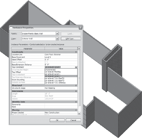
To find out what level an element is associated with, select the element and check its element properties. The word Level will appear for most content in the Instance Properties dialog box. You can see this readily by looking at the instance properties of walls, where there are two constraints to levels: one for the base of the wall and one for the top. These parameters are named Base Constraint and Top Constraint, as shown in Figure 4.2.
Furniture and fixtures all have a relationship to a level as well. Figure 4.3 shows the instance properties of a lamp family and its constraint to Level 1.


Levels generate new plan and ceiling views when created using the Level tool
Grids are created using the same method. The Grid tool
When a level or grid is selected, some text turns blue and additional controls appear:
- Blue text
A blue font indicates that text is editable. Clicking the text allows you to edit values directly.
- Drag controls
Drag controls

- Break controls
Break controls

- Locks and implicit alignment lines
Locks and implicit alignment lines

- Check box icons
Check box icons

- The 2D/3D extents icon
The 2D/3D extents icon


Grids are vertical planes used as standard references in the construction industry for creating location grids on the site. These construction planes are used to accurately define locations for elements such as columns and beams. In Revit, when columns and beams are placed on grids, they're automatically constrained to grids and grid intersections. As with a level, when a grid is moved, associated elements move with the grid. As you can see, the creation, graphic representation, and control editing of grids is similar to that of levels (Figure 4.5).
Note
A grid is composed of a line, a symbol, and a unique grid number or letter. Revit does not let you give two separate grids the same name, just as it won't let you assign the same name to two separate levels. This reduces the possibility of generating uncoordinated data.
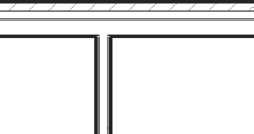
Walls are one of the basic building blocks of architecture, and are easily constructed with Revit. Walls are built from layers of materials that give the wall thickness — they aren't a mere collection of parallel lines. Each material has a user-definable representation for cut and projected geometry, which makes it possible for walls to be represented properly depending on the type of view the wall appears in. For example, when you draw walls in plan view (see Figure 4.6), you see the wall as if it were being cut, with materials represented as abstract hatch patterns. When you look at the same wall from an elevation or in 3D view, you see materials represented with a more realistic expression. You can see how materials are defined by opening the Materials dialog box from the Manage tab. You'll see that each material has a projection and cut pattern associated with it. Any of these materials can be used in the construction of your walls. You can also define your own custom materials here.
The materials in walls can be designed to provide automatic layer routing, thus greatly reducing the need to manually deal with wall intersections. For example, the stud layers connect with other stud layers and bypass finish layers, creating clean join representations automatically.
Wall layers are properties of each wall type (see Figure 4.7) and can be accessed through the Type Properties dialog box.


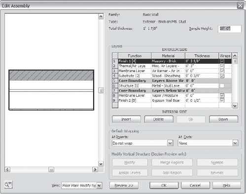
When the Instance Properties dialog box is open, click the Edit Type button to access the type properties. In this dialog box, you can then access the Edit Wall Assembly dialog box by editing the Structure parameter (see Figure 4.8).
These properties allow you to define a hierarchy of materials so that when the walls in Revit dynamically join (see Figure 4.9), Revit knows how to properly show the joint condition.
Curtain walls are a special type of wall (usually known as a hung façade) that allows you to divide the wall into a grid that regulates panel and mullion placement. An example curtain wall is shown in Figure 4.10. Panels and mullions can be customized to meet most design requirements, from metal panels to structural glazing. As with basic walls, curtain wall height is controlled by setting base and top constraints to levels or offsets from specific levels. You can also attach the top and bottom of curtain walls to floors and roof, and may also have top/bottom attached. See Chapter 6, "Extended Modeling," for more details on curtain walls.

The Wall tool is located in the Build panel of the Home tab. With this tool, you can create basic walls, curtain walls, and stacked walls in plan and 3D views. Making a wall involves using the Draw panel, which provides several methods for making walls:

The most common method is to draw walls using a multipick interaction — defining a start and end point for each wall as if you were drawing it. In the Draw panel, you'll see some standard drawing tools that will let you draw arcs, circles, rectangles, and polygons. You can also pick existing lines and generate walls with a single pick. Using the pick face method, it's possible to place walls on more complex geometric massing shapes with a single pick. We cover the specific methodologies in more detail in exercises throughout this book.

Floors, roofs, and ceilings are similar to walls in that they're built of layers of materials and are constrained to levels. The interface for creating and editing layers of construction is nearly identical to that of walls, as you'll see in this chapter's exercises. Floors and roofs also use the same material layer routing as walls, making connections between walls, floors, and roofs appear correctly (shown in Figure 4.11).
These tools are found in the Build panel on the Home tab. All of these elements are sketch-based elements made by defining a 2D boundary in a boundary edit mode. When you activate these tools, a contextual tab will appear with a set of tools specific to sketching 2D shapes. In this mode, you draw lines that represent the extent of the element as if it were projected onto a 2D plane. When you draw a closed loop of lines and finish the boundary, Revit generates 3D geometry for you.
In the case of floors, the geometry is coplanar with the boundary and has a predictable outcome. With more complex forms, such as hipped roof configurations, the resulting geometry is less obvious from within the boundary edit mode. The underlying 2D lines are always just a click away and can be easily manipulated to achieve your design objectives.

Figure 4.12 shows some common roof forms that can be made using Sketch mode.


Revit makes adding doors and windows to your model a snap. The key thing to understand about windows and doors is that they're hosted by walls. Without a host wall, doors and windows can't exist in your model. Figure 4.13 shows a window hosted by a wall.
Windows and doors always stay in line with a wall; when the wall is moved or rotated, the windows and doors also move and rotate. Likewise, if a wall is copied, all hosted elements in the wall are copied. Like everything else in Revit, windows and doors are associated with a level in order to streamline the design process and remove obstacles to iteration by reducing the need to manually fix the model. Changing floor-to-floor heights will always keep your windows and doors in proper relation to the floor they belong to.
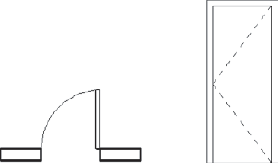
Windows and doors have specialized representations that are specific to the view in which they're placed. For example, in plan view, a door can be shown as open with an abstract door-swing graphic, whereas in elevation it appears closed and the door swing is shown as diagonal lines indicating the hinge side (see Figure 4.14). Given the fact that graphical symbology varies across the world, Revit is designed to allow you to represent these however you see fit; whether you want a door swing to be an arc or a straight line, or to be shown at all, is at your discretion. Customizing content to suit your needs is always just a few clicks away.
To place a window or door, use the tools in the Build panel on the Home tab. Windows and doors can be placed in any view except perspective view. Move your cursor into the view. A preview graphic of the element appears on your cursor when it hovers over valid hosts. Pressing the spacebar will rotate the element prior to placement. When you're ready to place the window, click to place it; it will automatically cut out material from the host wall. If you need to change the swing direction, press the spacebar when the door is selected, and it will cycle through all possible configurations.

Windows and doors are just a subset of the possible components that can be created using Revit. Revit allows you to design, create, and place just about any kind of component you can dream up. The predefined categories of component types include everything from casework to structural framing. Components are a bit more flexible than windows and doors in that they do not have to be hosted by a wall in order to exist in the model. A piece of furniture, for example, does not need a wall in order to be placed. At the same time, you can design components with the same dependency as windows or doors. For example, with a wall-mounted light fixture (Figure 4.15), you'd expect it to move with the wall and be deleted with the wall just like a window or door would. Revit allows for this flexibility when designing components.
To place components, use the Component tool in the Build panel on the Home tab. You can also drag and drop components from the Families node in the Project Browser. When placing components, you'll get helpful snapping and alignment graphics. Pressing the spacebar before placing a component will rotate it.

Most buildings have stairs, and where there is a stair, you're likely to encounter a railing. Revit provides specially designed tools for the creation of stairs, ramps, and railings that give you control over their basic constructive parts. With stairs, you set up design rules for elements such as stringers, treads, and risers; then Revit goes to work building the 3D geometry for you. You create stairs in Revit using Sketch mode, where you can define stair boundaries, risers, and runs by drawing 2D lines for the boundary and risers. The lines are then used to automatically generate a smart parametric 3D stair element of nearly any level of complexity. The same is true for railings. Using design rules, you establish a pattern of rails and balusters and then draw a simple 2D path. Revit fills in the path with 3D geometry based on the rules you establish. Figure 4.16 shows a typical Revit stair.
The Railing, Ramp, and Stairs tools are located in the Circulation panel on the Home tab. When you activate these tools, you enter a special Sketch mode where you sketch 2D lines. The lines used to construct stairs define the boundary and the risers. When you finish, Revit builds the 3D geometry for you. Changing the appearance and design rules for stairs and railings is done through the Type Properties dialog box. Ramps use the same creation method as stairs, and will slope between landings.


Stairs can be set to be multistory, so that if your building is a six-story building and five have the same floor-to-floor height, you can draw the stair and the railing once and have it automatically repeat through multiple levels. This is an instance property of any stair (see Figure 4.17).
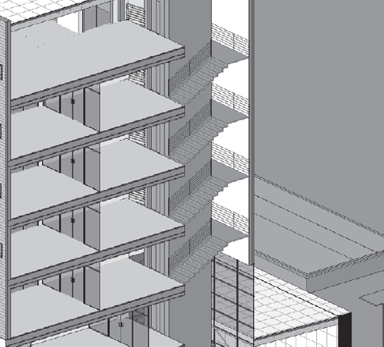
If the stair is drawn with a railing, the railing is also drawn on all multistory stairs. If you later decide to make any changes to the stair, you'll need to change it only once, and the change will propagate throughout all floors. Figure 4.18 shows a staircase (one element) spanning multiple floors.
In the following exercise, you'll use some predrawn lines to help you begin laying out exterior and interior walls. This does not mean that you'll always need or have such lines to begin using Revit. We do it here so you can move through the exercise efficiently and to avoid burdening you with typing in every dimension value. In real life, there are many different ways to start a project — from an existing 2D import (covered in Chapter 7, "Working with Other Applications"), from a conceptual massing form, from an imported image, or from scratch. As you will see, Revit has many useful features when laying out walls, especially the smart temporary dimensions that let you see and edit dimensions of elements before and during creation.
In the exercise, we will start with a set of lines and construct 3D walls using these lines as guides. The lines are named guides, and their graphic appearance is managed from the Line Styles dialog box accessible from the Manage tab, in the Settings fly-out menu. To follow along with the process of building exterior and interior walls throughout the rest of this chapter, open the exercise base file named Source_House_Walls_Start.rvt at the book's companion web page, www.wiley.com/go/introducingrevit2010. The model opens with the Level 1 plan view active. Several levels are predefined for first and second floors as well as for some roof planes.
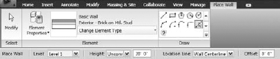

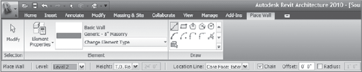
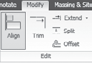
Click the Wall tool in the Build panel on the Home tab to begin the process of drawing a wall. Before you start drawing anything, notice that a new tab, Place Wall, has focus. Check the horizontal Options bar (Figure 4.19) just above the view. The options you see here are always specific to the selected tool — in this case, the Wall tool. Become accustomed to looking at the Ribbon for contextual tabs, as well as using the Options bar for tool-specific options. We covered some of the basics of the available options in Chapter 2, "Getting Acquainted: Interface and File Types," but here we'll talk more about the wall-specific options.
The first part of the Place Wall tab is accessible upon expanding the Change Element Type button, which lets you choose the type of wall element to create. Go ahead and choose the Basic Wall: Exterior Wall.
The nice thing about the type selection list is that even if you place a generic wall initially, you can change the type of wall later by selecting it and changing the type with the same mechanism.
Note
When new users start using Revit, they often wonder what level of detail they should model to when starting out. It's okay not to know that right from the start. Revit is designed to easily change any wall type to another later in the process without losing any intelligence or relationships with other elements. It's natural to use more generic, abstract wall types when beginning a design process and refine the model later. At the same time, Revit also allows you to be specific from the get-go. If you know your interior walls are wood studs with gypsum wallboard, you can start placing those immediately.
The next set of options is the gallery of methods for making the wall. You'll use the default option, which uses a drawing metaphor and allows you to draw walls as you would lines. Near the bottom of the gallery are two options that let you select existing lines or geometric faces to autogenerate a wall without drawing. These options are generally used if you're working from an imported set of lines, an imported solid geometry, or a massing form made of geometric faces.

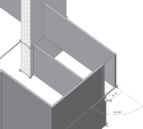
Next you define the height of your wall using the Options bar. You define which level the top of the wall is constrained to, or if you want the wall to have a specific fixed height that isn't tied to a level. In Revit, when the top of a wall is not tied to a level, this is referred to as its unconnected height. A knee wall is an example of a wall that isn't necessarily tied to a level at the top but needs an explicit height from the base level.
The next feature on the Options bar is the Location Line parameter, which is really the wall's justification. The location line allows you to set a fixed axis for the wall based on the built-up construction of the wall. The most common use of this is to draw with either the interior or exterior core boundary (as in Figure 4.21) or structural layer when laying out walls. For example, you can draw walls relative to the stud face, rather than the finish face, of gypsum board. Whatever is set here determines where your cursor is relative to the wall construction during creation. You'll notice this when walls are selected as well: the drag control is located at the location line. Note that you can change the wall location line at any point using the Element Properties dialog box for walls.

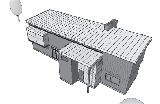
Let's start the exercise. For the remainder of this chapter you'll make the small house shown in Figure 4.22. Make sure you've got the file, Source_House_Walls_Start.rvt, open. Follow these steps:
Select the Wall tool from the Build panel on the Home tab. Using the Type Selector, set the wall type to Basic Wall: Exterior Wall.
Using the Options bar, set Location Line to Core Face: Exterior. This will allow you to draw the wall using the structural core edge as a baseline, rather than a finish layer or wall centerline.
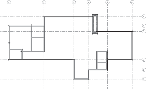
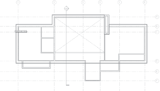
Starting in the upper-left corner of the sketch, begin tracing the outer edge of lines with your wall. Move in a clockwise direction, drawing walls from left to right (see Figure 4.23). As you do this, take note of snapping as you move the cursor from point to point. Snap your walls to intersection points of the guidelines. Zoom and pan while drawing walls — try this by scrolling the middle mouse button zoom, and holding the middle mouse button down to pan while drawing your walls. To avoid snapping to the wrong points, zoom in and trace the sketch. Revit provides snapping that lets you be precise in your wall creation by looking for endpoints, midpoints, and perpendicular edges (among others).
Notice the dimension strings that appear as you draw the walls. These are temporary dimensions that indicate the dimensions of the objects you're drawing and, more important, can be used to specify explicit length and angular values. (To try them, click one point as the start of a wall and start typing a value on the keyboard. Revit won't need any units or X–Y coordinates.) Use snap intersections to place walls. Temporary dimensions can be used to get a more precise placement, as shown in Figure 4.24.
Note that the blue guidelines are obscured by the wall as you draw the walls. This is because the walls you're drawing have a physical height in the model and are being represented as if cut at 4′ (1.2 m) above Level 1. What you see isn't just lines, but the cut face of the wall geometry, which obscures the lines below. This type of display is called hidden line. It means that geometry is displayed relative to your point of view: elements closer to you will obscure elements farther away.
Continue drawing walls until you complete a circuit of lines around the perimeter. If you want to stop drawing walls, press the Esc key twice, or click the Modify tool in the Place Wall tab. If you misdraw a wall, you can select the wall and use the drag controls to snap it to the correct location.
Note
Drawing walls from left to right on the screen places the exterior face of the wall facing the top of your screen by default. If this isn't the desired orientation, press the spacebar while drawing the wall, and it will flip. The flip controls are always drawn on the exterior side of walls.
Once you complete the walls around the perimeter, toggle the view display to Shading with Edges using the keyboard shortcut SD (press S, then D); the display mode will change to Shading with Edges. This option also appears at the bottom of each view in the View Control bar, as shown in Figure 4.25.
Use the Tab-selection method by hovering the cursor over one of the walls without clicking it, and then press the Tab key once. You'll see the chain of connected walls highlight. Click once to select the walls. Use this method to quickly select connected walls rather than picking walls individually (see Figure 4.26).
Now that all these walls are selected, you can change the wall type with one click (Figure 4.27). To see this, Tab-select all exterior walls, and then use the Type Selector and change them from Basic: Exterior Wall to Basic: Exterior — Brick on Mtl. Stud.
All the walls should have become thicker. This isn't the effect we want to have, so press Ctrl+Z to undo the type change.


Let's use a similar method to make the fireplace walls:

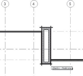
Zoom into the area between gridlines 4 and 5, where we will put the fireplace (see Figure 4.28). Hold down the Ctrl key and select the three walls. Note that the cursor changes to show a plus symbol (
+), indicating that each selection will add to the current selection.Note
To remove elements from a selection, press Shift and then pick elements that are already selected. To add new elements to a selection, use the Ctrl key when making selections.
Use the Type Selector to change the walls to Generic − 8″ (20 cm) Masonry. The walls maintain their exterior face justification and expand inward. Notice that the cut graphic changes as well — to a diagonal crosshatch. See Figure 4.29.
Select the far-left shortest segment of the fireplace wall and extend it by dragging the blue end grip control (Figure 4.30).
Continue by selecting each wall individually and dragging the end controls until they snap to the guideline intersections (Figure 4.30).
All that's left to do is draw the last segment and close the fireplace walls. To do that, select only one of the masonry walls of the fireplace, right-click to open the context menu, and select Create Similar (Figure 4.31).
This command puts you directly into drawing mode. Note that the Create Similar tool also appears on the Modify Wall tab when a wall is selected. Draw the remaining section of the fireplace. If you start drawing from the left corner, the wall is drawn inside-out. To resolve this, press the spacebar to flip the wall on its location line while drawing. Figure 4.32 shows the wall before it's flipped and after it has been corrected.
Note
Even if you draw the wall inside-out to begin with, you can always flip it later by selecting it and pressing the spacebar. The spacebar is a generic method for rotating objects about one or more axes. This is one of the beauties of Revit: there are no rules for when you do what; everything is changeable and replaceable later.
Let's change the height of the fireplace walls to go up to a predefined level in the model. Using the chain selection method described earlier, hover the cursor over one of the masonry walls and press Tab once. The four walls forming the fireplace highlight. (If this doesn't happen, select the walls individually by pressing the Ctrl key or box-select them — whichever method works best for you.) Click to select them.
Right-click the fireplace walls and choose Element Properties from the context menu.
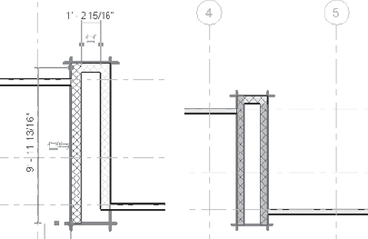
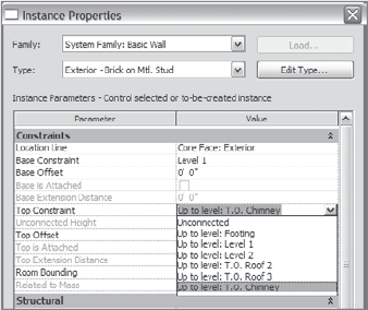
Change the top constraint parameter to T.O. Chimney, as shown in Figure 4.33. Click OK to commit the change.
Click the Modify button, or press the Esc key twice to exit the wall creation mode.


Let's assume you are now at a stage in the design where you know exactly which type of walls you are using. You'll be able to change some walls to more specific types using the Type Selector. You'll see how easy it is to deal with design changes using Revit. Follow these steps:
Select the walls as indicated in Figure 4.34, and change them from Basic Wall: Exterior to Basic Wall: Panelized Wall using the Type Selector.
Let's see what the 3D view looks like. From the Quick access toolbar, click the 3D button


You will now move to the second level. Start by adding exterior walls to it:
From the 3D view, select the wall running into the fireplace, as shown earlier in Figure 4.31. Open the Element Properties dialog box, and change the top constraint to Level 2. You do this because the bedroom on Level 2 needs to cantilever over Level 1, and you don't want that wall going through the bedroom. Figure 4.36 shows the wall before and after the constraints have been changed.
You can add some walls to the model directly from the 3D view — a nice benefit of working with a building model. Activate the Wall tool and choose Basic Wall: Exterior Wall. Using the Options bar, set the level to Level 2, and set the height to T.O. Roof 3 (see Figure 4.37). Make sure the Location Line is still set to Core Face: Exterior.
Start drawing the wall from the intersection of the guideline and the fireplace, and turn the corner to meet the other wall, as shown in Figure 4.38.
Perform a similar operation to create a bump-out for the master bedroom; this will become a closet later (see Figure 4.39). Before you start drawing, make the wall type Basic Wall: Panelized Wall, and draw it from right to left so that the panel material faces the exterior.
To give the house a bit more variation, let's bring down the height of walls for the front entry and the walls in the back, as shown in Figure 4.40. Multiselect the walls as indicated, using the Ctrl key, and then open the Element Properties dialog box and change the top constraint to T.O. Roof 2. Click OK to commit the changes and dismiss the dialog box.


Everything's looking good so far. Now you'll add some interior walls to the project:
Open the Level 1 plan.
Select the Wall tool and choose Basic Wall: Interior – Thin.
In the Options bar, set the height to Level 2 and Location Line to Wall Centerline. Begin laying out the interior walls using the guidelines provided in the view, as shown in Figure 4.41.

Not all of the interior walls are lining up neatly with exterior walls. Let's fix that. You'll first change to a thicker wall and then unjoin the wall. You'll use the Align tool to make things line up, and then rejoin the walls. Follow these steps:
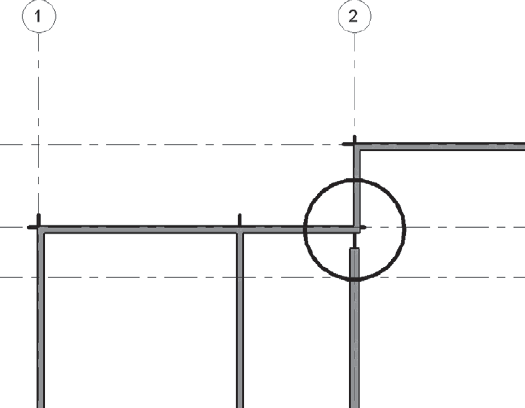
Zoom into the grid 2 join condition where the interior wall hits the exterior, as shown in Figure 4.42. You need to clean this up.
Change the wall type to Basic Wall: Interior Wall – Thick. You do so because this wall will span two levels and also act as a plumbing cavity.
Grab the wall-end control and drag it away from the join, as shown in Figure 4.43.
Note
If you don't detach the join, then you won't be able to realign the walls to the finish face. When you're dealing with complex joins such as this, the best practice is to pull the walls away from the join, make proper alignments, and then rejoin the walls.
Select the Align tool from the Edit panel on the Modify tab. You'll use it to align the finish faces of the two walls. This tool allows you to make alignments between elements and constrain that alignment if you desire. Walls that are connected automatically attempt to stay aligned. (Users often comment that the Align tool is one of the most useful tools in Revit. The thing to remember is that the first pick is where you want to align to, and the second pick chooses which element you want to move [align].)
Select the geometry (the horizontal wall) that you want to align. This is the target that you want other geometry to align with. Then, choose the geometric edge that you want to align, as shown in Figure 4.44 — in this case, the thick interior wall face.
Drag the wall end back into the join. The walls clean up, and you get a nice-looking image like the one in Figure 4.45.
Now that the wall looks good, change its height so that its top constraint is T.O. Roof 3 using the Element Properties dialog box. Check out your results in the 3D view; see Figure 4.46.
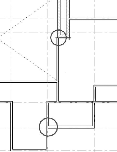
Using the technique you just went through, clean up the condition shown in Figure 4.47.


Now you will continue to add interior walls, this time to Level 2:
Open the Level 2 Floor plan and place Basic Wall: Interior Wall – Thin walls using the guidelines as placement aids.
Using the Basic Wall: Interior Wall – Thin wall type and the Pick tool located at the bottom of the Draw panel, pick the lines in the view. Before picking, use the Options bar to set Location Line to Wall Centerline and Height to T.O. Roof 3.
Be sure to clean up the walls highlighted in Figure 4.48 to achieve aligned walls and clean joins. Use the same technique used in Level 1 by pulling the join apart and then using the Align tool as shown in the figure.
The model has a large double-height volume for the main living space. A knee wall will be used to bridge the two bedrooms on either side of the volume. Using the Element Properties dialog box (see Figure 4.49), select the wall and change its top constraint from T.O. Roof 3 to Unconnected.
Set the Unconnected parameter value to 3′-0″ (1 m). Click OK to commit the change.
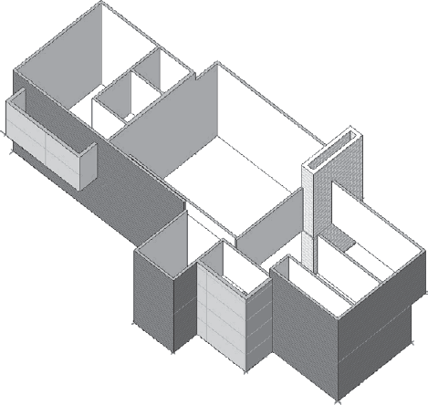
Excellent job! Now you have the beginnings of a small house (see Figure 4.50). The next exercise will pick up from this point and continue to add more detail to the model.

Now that you've built the exterior and interior walls, you'll add floors and roofs. You can continue where you stopped on your file, or open the file Source_House_Floor-Roofs_Start.rvt.

In this mode, the model becomes halftone and noneditable. A specialized set of contextual tools appear as a new tab named Create Floor Boundary tab, as shown in Figure 4.51.
The default state puts you into the Pick Walls command. This allows you to create the boundary of the floor by picking walls in the model to create a parametrically associated floor boundary. A boundary is a series of connected lines that form closed shapes. Boundaries can form multiple closed shapes, but lines can't intersect or be left unconnected at an end. Revit uses the term loop to define a closed boundary.
Note
A boundary must follow some basic rules in order to generate geometry. It needs to form a closed loop of lines that do not overlap or have unconnected ends. Lines cannot be left floating around, overlapped, or disconnected; otherwise, the sketch cannot be finished. If your boundary is invalid, Revit will warn you and even highlight the problem areas so that you can fix them on the fly (close the loop) and finish your sketch.
Using the Pick Walls option, hover your cursor over an exterior wall but don't click on it. Press the Tab key; the chain of all connected walls highlights. Now click once on the wall. Lines will be generated from the walls, as shown in Figure 4.52.
Not all the walls along the perimeter were selected. This is because the fireplace walls aren't connected at their ends with other walls in the selection. To finish the floor boundary into a closed loop of connected, you need to select the fireplace walls; this will generate lines over those walls. Finally you will need to clean up the lines. Trim the lines so they don't overlap and trim perfectly in a closed loop. If you attempt to finish without adding lines around the fireplace or without trimming and connecting them, your boundary will be invalid and you'll get the warning shown in Figure 4.53.
The final boundary lines should look like Figure 4.54.
The lines intersect and will need to be cleaned up in order to complete the floor boundary. The Trim tool is great for these conditions. Let's continue:

Select the Trim tool from the Edit panel on the Modify tab.
Select pairs of lines to trim. The first pick is any line you want to trim. The second pick is the line you want to trim to; you'll see a preview of the result, as shown in Figure 4.55.
Do the same for the other overlapping lines to complete the floor boundary (see Figure 4.56).
Now that the boundary lines look good, click the Finish Floor button located at the far-right of the Ribbon. A 3D floor will be generated.
Open the 3D view and you'll see the floor. Select it by hovering the cursor over an edge of the floor and clicking when it highlights. (You can press Tab to select it if it doesn't highlight immediately.) The floor can be reedited using the Edit Boundary button on the Modify Floors contextual tab. Figure 4.57 shows the floor in 3D.


Revit has some great copy and paste features that allow you to paste elements from one view into another with relative ease and also keep elements lined up in 3D space. In this section, you'll copy and paste the floor from Level 1 into Level 2 and then edit the floor boundary lines to match the design:
Select the floor in the 3D view, and copy it to the clipboard using Ctrl+C.
To paste the floor, choose Paste Aligned from the Clipboard panel on the Modify Floors tab. Choose Levels by Name from the drop-down list and select Level 2, and click OK (see Figure 4.58). The floor is pasted into Level 2.
Select the floor you just pasted, and click the Edit Boundary button on the Modify Floors tab. This will put you back in Modify Floor Boundary mode, where you can amend the lines to accommodate the new shape of the floor plate on Level 2.
Switch the view to Level 2 plan so that it's easier to visualize the relationship of the lines to the walls (see Figure 4.59).
As the floor plans for each level are not the same, you'll need to adapt the lines to meet the shape of the second floor. To do this, start by adding lines to the interior to make way for the double-height living room. Using the Pick Walls tool, select the two interior walls shown in Figure 4.59.
Do the same for the walls that cantilever over Level 1. You'll get a warning about keeping elements joined when picking the cantilevered wall (see Figure 4.60). Click the Unjoin Elements button in the warning dialog box to continue.
Using the Trim tool, clean up the sketch lines to form a continuous loop of lines. The untrimmed lines are shown in Figure 4.61. After trimming the lines, delete the leftovers.
You need to continue editing the boundary lines to include the bump-out in the lower-left corner of the model and account for the stairwell. To do this, first pick the bump-out walls using the Pick Walls tool. If the pick puts the line on the inside of a wall, click Flip Arrows to toggle the line to the outside face. For the stairs, delete lines that you don't need.


Next, you'll clean up the lines to form a closed loop. Here are the steps:
Use the Split tool to split the horizontal line into two segments, as shown in Figure 4.62.
Complete the loop by trimming the lines to one another.
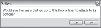
Click Finish Floor in Ribbon. A dialog box opens, asking if you want the walls to attach to the bottom of the floor (see Figure 4.63).
Click Yes. The interior walls will connect to the bottom of the floor. This ensures that section views of the model look correct. When walls are attached to floors, they dynamically adjust their height to match the bottom of the floor, even when floor thickness is changed or given an offset from a level.
The next dialog box asks if you want to join the floor with wall geometry (see Figure 4.64). Click Yes.

This option automatically joins walls that overlap with the floor — in this case, the exterior walls. The resulting graphics manifest in section views, producing a cleaned-up relationship between the layers in the walls and floors.

Now that you've created the basic floors, you'll add some roofs to the house. Roofs are created in the same manner as floors: as boundary lines that relate to a level in the project and that define the base shape of the roof. As you'll see, roofs allow you to specify slopes for each line in the sketch, which lets you rapidly create hipped, gable, shed, and flat roof configurations. Follow these steps:
Open the Level 2 floor plan.
Use the Pick Walls option in the Draw panel. Look at the Options bar, and set the roof overhang to 1′–0″ (30 cm). This will offset the roof boundary line from the wall to produce a parametrically associated overhang.
Hover the cursor over an exterior wall and press Tab. When the perimeter walls are highlighted, click to select them. The beginning of the roof boundary is created, as shown in Figure 4.65.
Delete lines over the staircase — you'll add a separate roof over that area later. Figure 4.66 shows the lines to delete.
Use the Trim tool to form a closed loop and get the sketch to look like that in Figure 4.67.
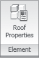
Once you've defined a slope in a roof, this can be changed from outside of Roof Boundary edit mode. Simply select the roof, open the Element Properties dialog box, and then change the Slope parameter value.
Look at the model in 3D.
Select the roof, and use the type selector to change its type from Basic Roof: Generic − 12″ to Basic Roof: Metal Roof. The metal roof has a pattern of lines that represents standing seam roof panels defined in the type properties of that roof type (see Figure 4.70).
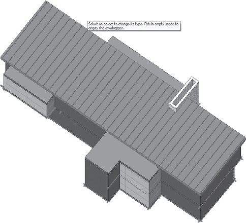
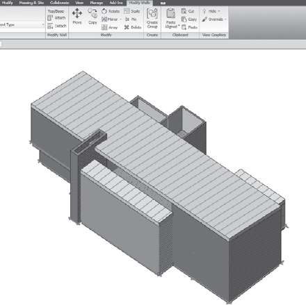
If you spin the model to the side, you'll notice a gap between the top of the walls and the roof. This is easily rectified using the Top/Base Attach options available in the Modify Wall panel when walls are selected. In Figure 4.71, you can see where the walls aren't attached to the roof.

Spin the model a bit, and then use the Tab-selection method to select the exterior walls.
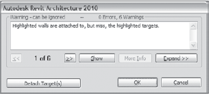
Click the Top/Base: Attach button in the Modify Wall panel, and then select the main roof. The walls extend up to meet the underside of the roof. When you get the warning message shown in Figure 4.72, click Detach Target(s). This detaches walls that aren't entirely below the roof (the walls in the foreground).
The resulting geometry should look like Figure 4.73.
The great thing about the Top/Base: Attach tool is that if the roof pitch is changed, the walls will parametrically adapt to the new slope! To experiment with this, select the roof and open the Element Properties dialog box. Change the roof slope, and watch as the walls dynamically update.


You'll now add the remaining roofs and make walls attach to them:
Open the plan view T.O. Roof 2 using the Project Browser.
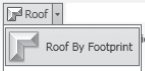
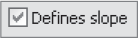
Start with the roof in the lower left in Figure 4.74. Use Roof by Footprint, pick the three exterior walls, and then draw the last line to make a closed rectangle. Also using the Options bar, set the overhang to 0′-0″, and make sure all the lines are non-slope-defining.
When you've got a closed loop of lines, click Finish Roof.
Create additional roofs over the entry and the main living space (see Figure 4.75) using the same techniques. Make one roof for each condition.
Note
Here are some best practices for roof creation. When walls are already created in your design, use the Pick Walls tool in the draw panel. Then, switch to drawing lines to finish drawing the roof boundary. Use the Trim tool to clean lines and get rid of any overlapping or unconnected lines. When no walls are present or the base geometry of the roof doesn't match the geometry that the exterior walls create, go directly to drawing the shape of the roof.


Making changes to an existing roof is simple — you edit the boundary lines to match your design intent, then finish the roof to pop it into 3D. Go to the 3D view. If the roofs aren't already the Metal roof type, you need to change them. Using selection (picking the roofs) and the Type Selector (changing to the type you want) is a common method, but there is also a nice tool that lets you pick a type and then apply that type to other elements with a few clicks.
This tool is called Match Type, and it's located in the Clipboard panel on the Modify tab. To use the Match Type tool, click the tool, then select the type of element you want to convert other elements into. You then select elements of the same category, and they will change type with each subsequent mouse click. This tool works for the majority of existing Revit elements. Try it out:

Select the Match Type tool found in the Modify tab.
Select the main roof. Note that the cursor appears filled — as if you sucked that type into your dropper. With each selection, you can change types belonging to the same category (in this case, the category Roof; see Figure 4.76). Press the Esc key twice to exit the command.
Select the three roofs whose type you wish to change.
Next, you'll give these roofs a negative offset from the level to make room for some clerestory windows.
Select all three roofs by holding down Ctrl and selecting them. Open the roofs' Instance Properties dialog box, as shown in Figure 4.77.
Change the Base Offset to −1′-31/2″ (40cm), the thickness of the roof.
Select the walls below the roofs you just created, and attach them to the roof as shown in Figure 4.78.
When you get the error message shown in Figure 4.79, click the Detach Target(s) button. This changes the attachment of the wall so that it connects with the lower roof.

To attach the tops of the interior walls to the underside of a roof, you need to be able to select them first. With the roof in the way, this might appear to be a problem. To resolve this issue, you can temporarily make the roof transparent, select the walls through the roof, and then attach the walls. When you are done, reset the roof graphics to clear the transparency override.
Select the main roof, right-click, and select Override Graphics in View by Element from the context menu. Check the option to make the roof transparent, then open the Surface Patterns node and uncheck the Visible option. The roof will turn 100 percent transparent, and the surface patterns will be turned off (Figure 4.80).
Select the interior walls on Level 2 by holding down the Ctrl key when picking.
With walls still selected, click the Top/Base: Attach button in the Modify Walls tab, then select the roof.
Select the roof, and open the Element Overrides dialog box again using the context menu. Click the Reset button to clear all the overrides (Figure 4.81) and click OK to finish.


Note
To see the effect of the wall meeting the roof, you can temporarily hide the roof using the temporary hide/isolate tool in the View control
To add some clerestory windows to the design, you have two options: you can create a new window type or, even faster, you can use the Curtain Wall tool. Curtain walls are a special wall type that lets you place mullions and panels on a grid surface. Each gridline divides the wall into sections, which become panels. Mullions separate individual panels and are placed on curtain grids. For this exercise, you'll use a curtain wall where the mullions and panels are predefined in the wall type, and automatically embed themselves into basic walls when drawn on top of a basic wall. This makes layout extremely quick and easy to manage. You can continue with the file you created so far, or open the file Source_House_CurtainWall_Start.rvt. Follow these steps:
In the default 3D view, hide the main roof using the Temporary Hide/Isolate control located in the View Control bar. Select the roof, and then choose the option Hide Element from the View Control bar (see Figure 4.82).
Once the roof is hidden, use the Wall tool in the Build panel on the Home tab and set the wall type to Curtain Wall: Storefront using the Type Selector. In the Options bar, set Level to T.O. Roof 2 and Height to T.O. Roof 3.
Draw the curtain wall, as shown in Figure 4.83. Use snapping to get the correct placement.
Add a similar curtain wall to the opposite side of the model (see Figure 4.84).
Choose Reset Temporary Hide/Isolate from the View Control bar so the roof reappears.
Select the curtain wall at the back of the house, and attach it to the roof above using the Attach tool in the Modify Walls tab.
You'll get a message about elements becoming invalid. Click the Delete Element(s) button (see Figure 4.85). This isn't a problem; Revit is just letting you know that it needs to delete the elements in order to re-create them. The mullions will be regenerated once the curtain wall is attached to the roof.


Now that you have the clerestory windows in place, use the same tool to add a glass wall to the façade:
Open the Level 1 plan view and choose the Storefront curtain wall type again.
Set the Height to T.O. Roof 2 in the Options bar.
Draw the wall from the edge of the fireplace to the center of the wall (see Figure 4.86). A triangle snap icon appears when the wall's end hits the center.
Add a curtain wall on the other side of the fireplace as well, as shown in Figure 4.87. Set this wall's height to Level 2.
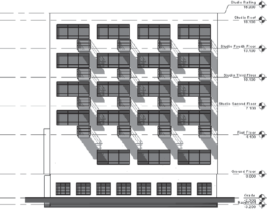
Open the north elevation. In this view, you can see the effect of the curtain walls you just made, as shown in Figure 4.88.
Select each curtain wall, and attach each to the roof above using the Top/Base Attach tool you used for the interior and exterior walls (the button on the Modify Walls tab). To select the curtain wall, hover the cursor over an outer boundary of the curtain wall until a dashed frame appears. Note that selecting a mullion or panel doesn't select the curtain wall.
You'll get the message shown in Figure 4.89 about mullions being removed. Again, this isn't an error; it's Revit alerting you to its process. Click the Delete Element(s) button to continue.


The curtain walls you've been placing preset the spacing of grids, which in turn determines the spacing of mullions and panels. You can deviate from the pattern interactively to make patterns that are more irregular.
To align the curtain wall on the north façade with the clerestory windows, activate the Align tool from the Modify tab. Select a curtain grid in the clerestory first, and then select the edge of the curtain wall. When selecting a grid, make sure you select a grid, not a mullion (press Tab when the mouse is over a mullion until the dashed line representing the grid shows up and then click). The two curtain walls should now be aligned.
Remove some grid segments and mullions to give the wall more interest. To do so, hover the cursor over the vertical mullion nearest gridline 4. Press the Tab key to cycle the selection until a curtain gridline highlights (be careful — not the mullion, but the curtain grid). Select this grid.
Note that the gridline has a pin icon associated with it. This indicates that the grid is locked into place and can't be moved interactively. This is because the grid is defined in the wall type — as a spacing rule. However, the grid can be unpinned and then moved interactively if you desire. Click the pin to unlock it, and drag the grid. For now, let's leave the grid pinned and only deal with removing segments of grids. You can see the pins in Figure 4.90.

To replace grids and mullions on the curtain wall, select a curtain gridline and use the Add/Remove tool again. Selecting on a dashed grid segment puts back the segment as well as the mullion.
Open the Exterior Perspective 3D view, and look at your model in 3D (see Figure 4.92). Remember, you can use Shift+middle mouse button to orbit the model in 3D.


Now that you've constructed the basic envelope of a small house, let's move back to the inside and place some windows and doors. Follow these steps:
Go to the Level 1 floor plan.
From the Build panel on the Home tab, select the Door tool.
Set the door type using the Type Selector to Single-Flush 34″ × 84″ (85 × 210 cm).
Move your cursor over walls in the model — note that the door previews before it's placed. If the mouse isn't over a wall, no preview appears, and the door can't be placed.
Place the door as shown in Figure 4.93.
Note
Note the helpful dimensions that appear during placement.

Temporary dimensions show up during and after placement to aid you in locating the door. Once the door has been placed, the dimensions become active controls that you can use to precisely position the door relative to nearby references, such as walls, grids, or other doors:
To edit a dimension value, click the numeric value, and it becomes an editable text field.
Clicking the blue squares of the temporary dimension cycles the dimension between centerlines and opening conditions.
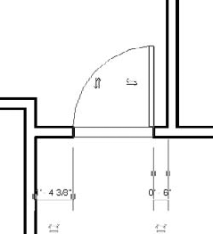
For example, after placing the door, select the blue control for the temporary dimension that snaps to the door centerline, and move it toward the door leaf. Note that the dimension jumps to a new location. Now, click the dimension value and set the distance to be 6″ (15 cm). See Figure 4.94.
You'll notice that the door was given a tag when it was placed. This is an option available in the Options bar during placement. For this exercise, you don't need to see tags yet. Go ahead and delete the tag (hover the cursor over the tag; if you can't select it, use the Tab key to cycle to it), and select the Door tool again. This time, uncheck the option Tag on Placement in the Options bar. This will prevent the doors from being tagged automatically from here on out.

Continue to place doors. When you're placing doors, get accustomed to using the spacebar to flip the door orientation and make the door face correctly. If you don't place a door correctly, it's no problem — select the door and press the spacebar until the door looks right. For now, place the same door so the image looks roughly like Figure 4.95.
Once the doors are placed, you can create constraints between the doors and nearby walls. This is useful if you want to maintain a specific relationship between a door and a wall so that if the wall moves, the door moves with it.
To do this, you'll convert a temporary dimension into a permanent dimension and then lock the dimension to create a constraint. You'll then delete the dimension but leave the constraint in place. Here are the steps:
Open the Manage tab, and then open the Settings drop-down and open the Temporary Dimensions Properties dialog box.
In the Walls options, select Faces of Core; in the Doors and Windows options, select Openings, as shown in Figure 4.96. Click OK to finish.
Go back to the view and select a door; notice that the behavior of the temporary dimensions is different — the dimensions follow your new rules when initialized. This will let you set distances between door openings and the stud faces in your walls with a few clicks.
Use the temporary dimensions to get the door opening 6″ (15 cm) from the stud face of the wall, as shown in Figure 4.97.
Click the icon that looks like a blue dimension string. This converts the temporary dimension into a regular dimension.
Select the dimension and click the lock icon. This creates a fixed constraint between the door and the wall (Figure 4.98).
Now, let's say you don't want to have that dimension when you print later — you just used it to set a rule. In this case, you'd like to delete the dimension but keep the rule you defined. When you select and delete the dimension, you'll get a warning message (see Figure 4.99); you can either unconstrain the condition or click OK and keep the constraint but still delete the dimension. Click OK.
Do the same thing for the door on the other side of the wall.
Select the wall, and the locks show up again, indicating the presence of a constraint. Clicking the lock (unlocking it) deletes the constraint. Figure 4.100 shows the constraints.
If you move the wall by dragging it or using the temporary dimension, the doors will also move. Go ahead and change the temporary dimension from 4′-8″ to 5′-0″ (130 cm to 150 cm) to see this work.
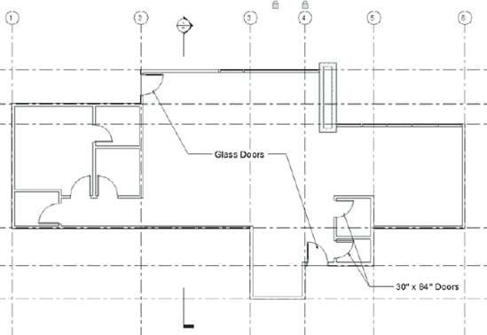
Place more doors in the project: glass doors for the exterior doors and smaller doors for the bathroom and the closet near front entry. Figure 4.101 shows additional door locations.
Changing door types is just like changing wall types. Select the door and use the Type Selector to swap the door with a different type.
For the moment, don't worry if you don't find the exact type of door you wish to use. We'll explain later how you can find more doors or adjust existing ones to serve your needs.


Let's continue to place doors in the model.
Open the Level 2 plan view.
Place the following types of doors in Level 2, as shown in Figure 4.102:
By-pass sliders
Single flush 34″ × 84″ (85 cm × 210 cm)
A pocket door
Use temporary dimensions to place door openings 6″ (15 cm) from stud faces, as you did on Level 1.

Placing windows is just like placing doors. Use the Window tool in the Build panel on the Home tab. You'll start by placing some sliders and then some fixed openings. The sliders have a fixed-size set in the type properties, and the fixed windows have instance-based sizes. We'll explore the behavior of both type and instance families. Start by placing windows:
In the Level 2 plan view, select the Window tool from the Home tab. Choose the type Slider with Trim: 7′0″ × 4′0″ (215 cm × 120 cm). Uncheck the Tag on Placement option. Place windows in the walls as indicated in Figure 4.103.
Place windows of type Fixed – Varied Size in the locations shown in Figure 4.104.


The Fixed – Varied Size window is designed so that its width and height are set to be instance parameters as opposed to the window you previously used, whose width and height were set to be type parameters. Setting the dimensions of an object to be instance parameters gives you the advantage of working with more flexible, directly editable elements; you can modify them with the blue grips that display when they're selected.
To see how to dynamically size a window using the blue grips, select the window and make it wider.
Note
Be aware that instance parameters, when changed, don't propagate that change throughout all similar elements in the project. The change is applicable only to that one instance of the element.


Feel free to change the sizes of the other windows you just placed by opening each elevation and making adjustments, as shown in Figure 4.105.
Let's place one more window. Open the South Elevation, select the Window tool, and choose the Fixed – Size Varies type. Place the window in the façade and adjust its size as shown in Figure 4.106.
Let's place one more window. Open the South Elevation, select the Window tool, and choose the Fixed – Size Varies type. Place the window in the façade and adjust its size as shown in Figure 4.106.
The windows you've placed are fairly generic. The beauty of Revit is that these windows can be swapped out with different window types on the fly at any stage of the project. Remember, it's never too late to do any changes in Revit. Content from the default libraries or from the Web, or your own custom-made elements can be loaded into the project and swapped. Try searching the web library for additional window and door types, and load them into the project:
Go to the Insert tab, then type your search into the Autodesk Seek search field.
Your browser will launch and take you to the Autodesk Seek site, where you can browse for content and save it to disk.
Browse for content and save it to your hard drive or other media (see Figure 4.107).
Once you've saved the content, select the Window tool and click the Load button located in the drop-down. This will take you to a file browser. Locate the files you downloaded and click Open.
Note
If you create library elements on your own or download them from the Web, make sure you create a separate folder to store these in. You can then specify this location as an additional path when loading content that shows up in the left pane of the Load Family dialog box. To add a new library, use the Options dialog box located on the Application Menu, at the lower right. Open the File Locations tab and click the Places button. Use the resulting dialog box to add a new Library location.
Note
Revit families can be dragged and dropped from Windows Explorer but not from the Web. If you have Windows Explorer open, try dragging and dropping a family (.rfa) file directly into your Revit project. You can also open a family directly using the Open option when downloading families. Doing so opens the family in the Family Editor — the tool used to design and build families. To get the family into your project, you can then use the Load Into Projects button located at the far-right side of the Ribbon.

For the next step, you're going to add furniture, plumbing fixtures, and other interior equipment in the building. You can use the file that you have created until now or open the file named Source_House_Components_Start.rvt from the book's companion web page.

Placing freestanding furniture is simple. Using the Component Placement tool in the Build panel on the Home tab populates the Type Selector with available components. The list doesn't include windows and doors, but it does have a mixture of other categories of elements. For example, furniture, plumbing fixtures, and plantings appear on the list. An example is shown in Figure 4.108.
Note
As this list is really long (and full of elements from multiple categories), you may find it easier to drag from the Family list in the Project Browser.
If you can locate the type of family you want to place, this method works fine:
Open the Level 1 plan view.
Choose the Dining Table and Chairs family from the drop-down list.
Move the cursor into the view. A temporary graphic representing the table and chairs appears on the cursor (Figure 4.109).
Press the spacebar prior to placement to rotate the table by 90°.

Next, continue placing more furniture components in the model: couches and tables. Follow these steps:
Place the Sofa Loveseat, Sofa Couch, and Coffee Table using the Component tool. Create the furniture arrangement in the living space.
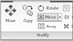
To mirror the Loveseat across from the Coffee Table, select the Loveseat, and then select the Mirror tool in the Modify Furniture tab.
Select the center reference of the table as the mirror axis. The Loveseat mirrors across this axis, creating a new instance (see Figure 4.110).

To place additional furniture elements, such as beds and nightstands, use the same technique. Use the Component tool, and choose appropriate families from the Type Selector. New to Revit 2010, the Type Selector shows visual previews of the content, which helps you make selections from the list. Open the Level 2 plan view, and place some beds to get familiar with this behavior.
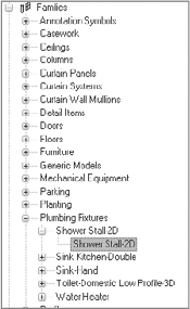
Placing plumbing fixtures follows the same paradigm as placing other components. However, for this exercise, you'll use the Project Browser rather than the Component tool to place your components:
Open the Families node in the Project Browser.
Open the Plumbing Fixtures node: this represents the category of element you wish to place.
Open the Shower Stall-2D node: this is the family name. The family types show up under this node (see Figure 4.111).
To place a component from the browser, drag the family type from the browser into the view. The visual feedback is exactly as if you chose the type from the Type Selector — the element appears on your cursor, ready for placement.
Drag the family into the view, and press the spacebar to rotate it.
Place it so that it snap-aligns to a wall. To see this, hover the component over a wall: the wall edge highlights.
Using the same method, place the sink (Sink-Hand) and toilet (Domestic-Low profile). The completed bathroom looks like Figure 4.112.

Note
Remember to use the spacebar before placement, and hover the cursor near walls to orient the object correctly.
Using the same technique, you can finish the other bathrooms in the model (Figure 4.113). Be sure to take advantage of the Place Similar tool by first selecting the component you want to duplicate (such as a sink or toilet) and then clicking the Place Similar tool that shows up in the active contextual tab. This puts the component onto your cursor, and you can bypass the need to search for content in the Type Selector or family browser.

Some additional families are loaded into the project, which you can experiment with. Using the furniture components in the project, attempt to create a kitchen configuration.
Figure 4.114 shows a stair in Sketch mode and 3D view. Different colors are automatically assigned to risers, boundary, and runs.


Stairs are considered complex architectural elements because their construction is dependent on local building rules defined in building codes. Revit allows you to set different rules based on your building code requirements. Just as with walls and floors, stairs are constructed using relationships to levels: all stairs have a base level and a top level that are used to calculate tread depth and height based on min–max rules. These parameters, shown in Figure 4.115, change from stair to stair and are the most important parameters used for constructing stairs.

Geometric variation of the individual elements of a stair (tread, riser, stringer, and so on) is managed with type properties that provide dimensional and material parameters. Figure 4.116 shows those type values.
The most important parameters are rules that establish minimum tread depth and maximum riser height. These values are used to automatically guarantee minimum and maximum distances to keep your stairs within the constraints of what your building codes dictate. Revit won't break these rules. Your stairs start and end where you want them, and the correct number of risers and treads are autogenerated for you when making the stair. You'll see this in the exercise later in this chapter.
You need to create a stair from Level 1 to Level 2 in your model. From the Chapter 4 folder on the book's companion web page, open Source_House_Stairs-Railings_Start.rvt. You'll start by sketching the stair in Level 1 and making sure it's going up to Level 2. You'll then look at the stair using a 3D sectional view and change the type.
Revit puts you into the Run tool by default. This tool autocreates boundary and riser lines as you draw a run line.

Now, let's discuss something briefly. When Revit prompts you to draw a stair run, it always uses the middle of the run as a justification point. Often, however, you won't have a reference to the location of the stair centerline. So, you need to either draw help lines at the distance from the wall that represents half the stair width or draw the stair in an approximate location and then move it into place.
To make this exercise useful for teaching you about other Revit editing tools along with the Stairs tool, you won't use a help line; instead, you'll draw the stair in a position close to the correct one and then adjust it to the right location using other tools. Follow these steps:

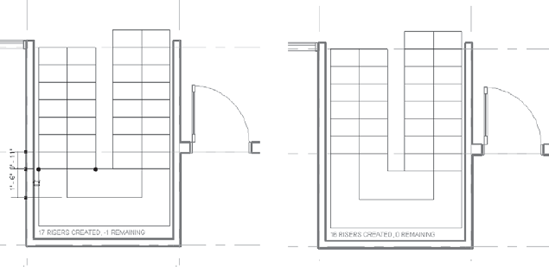
Start drawing the riser line by snap-aligning to the horizontal gridline to begin the run. (The blue dashed line indicates that snap.) As mentioned, the line is drawn through the center of the stair, with boundaries shown offset. A halftone text graphic also appears as you drag the run line. The text shows how many risers have been created and how many remain to get the stair from Level 1 to Level 2.
Drag the line until the text shows 8 RISERS CREATED, 8 REMAINING, and click the mouse once. This is where you'll break the stair for a landing. It should look similar to Figure 4.118.
Begin a new run line to the left of the first stair; snap the beginning of the run to the end of the last riser.
Draw the run until you see 16 RISERS CREATED, 0 REMAINING. This should be a point that is aligned with where you started the stair. You've created a stair return; your drawing should appear similar to Figure 4.119.
By default, railings are added to stairs when created. You can preset a railing type, or choose to not autogenerate railings. While still in Sketch mode, from the Tool panel, select Railing Type, and set it to None.

In order for the railings to work properly, you need to adjust the sketch a bit. Let's add a riser to the bottom of the stair and remove one from the beginning of the next run:
Drag the blue run line at the bottom segment of the stair until another riser appears. Revit will tell you that an additional riser is present (−1 REMAINING).
Delete the riser at the top of the first run of stairs, as shown in Figure 4.120.
There is a gap between the outer boundary of the stair and the bounding walls. You need to adjust the boundary lines to fit the model.
Note
The initial width of the run is set in the stair properties. This stair is set to 3′-0″ (90 cm), but you could change that to any value prior to drawing the run lines.
To make the stair fit between the walls, align the outer boundary lines to the bounding walls. Still in Stair Sketch mode, align the landing by selecting the Align tool, then the interior side of the wall at the bottom of Figure 4.121, and finally the landing boundary.
Next, you'll move the stair so it's centered in the stairwell. Using a crossing selection, select all lines in the sketch. Because you're in Sketch mode, no other model elements are selected, so you don't have to be too careful about what you select — Revit will grab only what's in the sketch. Now, follow these steps:
With the sketch lines of the stair selected, click the Move tool that is available in the Ribbon.
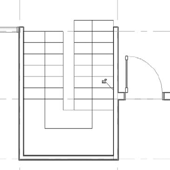
With the first pick, select the center of the stair boundary by the landing side, and then select the middle point of the wall. This should place the stair in the center between the two walls. You'll know you've found the center of the stair line and the wall when you see the triangular snap shown in Figure 4.122.
Use the Align tool to align the left and right boundaries to the wall. Select the Align tool, and then pick the inside edge of the wall on the right, and then the right boundary line of the stairs. Doing so aligns the right run to the wall. Repeat for the left run. Figure 4.123 shows the stairs, properly located.
You can also preset a railing type to be added to the stair and drawn automatically when you finish the stair sketch. Click the Railing Type button located on the Create Stairs Sketch tab

Finish the sketch to see the resulting geometry. To do that, click the Finish Sketch button. To visualize the stair in 3D view, go on to the next steps.


A great way to see the stair in an isolated 3D view is to create a section through the stair and then orient a 3D view to the section view. Here are the steps:
Use the Section tool in the View tab to draw a section, as shown in Figure 4.124.
Right-click the section, and choose Element Properties. Rename the view by changing the View Name property from Section 2 to Stair Section.
Open the default 3D view by clicking the 3D button at the top left of the application frame.
Click the Finish Stairs button on the Create Stairs Sketch tab.
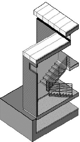
Select the section that you just created: Section: Stair Section. To change the view, right-click the View Cube in the upper right corner of the view and choose Orientate to Other View from the context menu.
The 3D view reorients and becomes cropped to the same crop extents as the section view. The view you see looks like a section through the stair, but it's a 3D cropped portion of the entire stair. Figure 4.125 shows the finished view.
To see the stair in 3D, press Shift+middle mouse button, and slowly spin the model (see Figure 4.126).
Right-click the view name 3D in the Project Browser and rename the view 3D Stair.
Saving with a new name saves the view as a unique view. The next time you click the 3D button in the toolbar, a new default 3D view that shows extents of the model will be generated for you.


Railings are also sketch-based elements that are generated from a 2D path (sketched line) and a set of design rules. Figure 4.127 shows some of the elements of a railing; the primary ones are the path, rails, and balusters. The path is made from 2D lines, the rails are made from 2D profiles, and the balusters and corner posts are made from 3D solid geometry.
Rails are simply 2D profiles that sweep along the length of the railing path. There can be many horizontal rails in a railing, and they can each be given a horizontal offset from the path to accommodate handrails and other more complex scenarios.
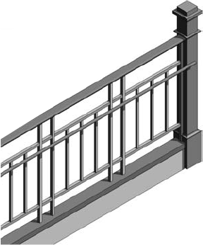
Balusters are 3D families that get arrayed along the length of the path. Don't think of a baluster as something that has always to be vertical and rectangular. In Revit, a baluster can be any geometry you wish to repeat at a regular interval. Figure 4.128 shows a post family and repeating baluster pattern.
Balusters consist of a main pattern (a unit that is repeatable) and posts. Posts can be start, corner, or end posts. They can also have varying geometry.
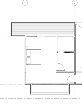
Railings can be freestanding elements or hosted by another element such as a stair or floor. To draw a freestanding railing, use the Railing tool located in the Circulation panel on the Home tab
You can have a single line as a railing (imagine a railing in the middle of a stair). But the moment you draw a second segment in the same sketch, Revit will expect you to connect them in a chain.
Once you've drawn the path and finished it, the rail geometry is constructed and conforms to the path. An endless number of railings can be defined using the combination of custom profiles and balusters. For this exercise, you'll add a predefined rail to the project and then change the type to make a different configuration. Follow these steps:
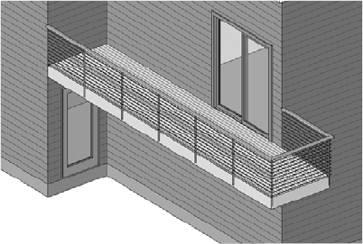
Open the Level 2 plan and start the Railing tool.
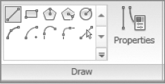
You will be put into Path creation mode. Using the Lines tool, draw a railing along the edges of the exterior deck, as shown in Figure 4.129.
Click the Finish Railing button to complete the railing.
Open the 3D view and spin the model to see the railing.
Select the railing and change its type to CABLE RAIL — CABLES using the Type Selector. The railing changes to a cable-style rail and looks like the railing in Figure 4.130.
Looking at the model, you can see the result of your railing path. Note also the presence of railings; Revit automatically places railings on stairs. The railings can then be changed or deleted as desired, independently of the stair. However, if you delete a stair with an associated railing, the railing will also be deleted. You'll also notice some modeling issues that need to be resolved. For example, the stringers are embedded in the wall, and you don't need that railing along the outside edge where you have the wall.
To fix the railing problem, select the railing in the wall and delete it (make sure you're selecting the railing, not the wall or the stair; help yourself using the almighty Tab key). Don't delete the internal railing.
To fix the stringer problem, let's change the construction a bit. Rather than have the stringers on the outside edge of the treads, you can move them under the treads — a more typical method for wood construction:
Select the stair, and open the Type Properties dialog box.
Scroll down to the Stringers parameters.
Change Right Stringer and Left Stringer from Closed to Open (see Figure 4.131).
Click Apply to see the effect in the model. The stringer geometry changes.
Feel free to experiment with other parameters available in the stair type properties. It's possible to create treads with nosing profiles or that have slanted risers, and to change the materials of each subelement in a stair or change the construction of the stair to monolithic.
Note
Note that you're editing type properties when changing how treads, risers, and stringers are defined — meaning that other instances of that stair (if you've drawn a couple of staircases in the building) will update as a result of type changes. To avoid undesirable changes, duplicate the stair first, name the new type, and then begin your experiments.


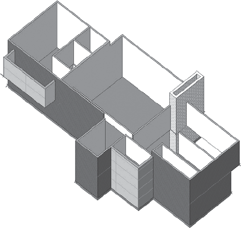
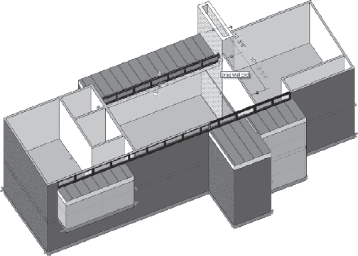
We just went through a series of exercises meant to get you familiar with the basic modeling tools available in Revit. The graphic below shows a final perspective view of the model you have created. Obviously, we did not get into the nuts and bolts of every tool, but with time you will begin to dig deeper and experiment with more of the features. Also, we will revisit some of these tools in Chapter 6, "Extended Modeling." Now that you have a basic model started, feel free to experiment with it: change the roof, lay out a kitchen, load some additional doors and windows. Most of all, have fun, be creative, and be patient with yourself and the software.