
Now that we've discussed how to annotate a drawing, be it for presentation or production, we will review how to create the set of documents that will be used by the contractor and subcontractors to build the project.
In this chapter, we'll go into detail about preparing the construction document set. Topics we'll cover include:
Formatting your documents
Creating schedules
Using drafting views
Understanding drafting tools
Importing CAD details
Reusing details from other projects
When you begin documenting your project, most of your modeling should be more or less complete. That doesn't necessarily mean that you have all your views established or all your sections cut, but it's helpful if the majority of your building geometry is in place.
To illustrate, let's go back to the house we've been working on. By this point the geometry of the house should be well established. To begin the documents, you'll create a series of views of the model. You've already established some views in the model. Some were in the Revit template file, and you made others while creating the model. However, the views you currently have for the floor plans are set up for presentation purposes and are not suitable as construction documents. Therefore, we need to create new views, customize their appearance, and place them onto sheets to make digital or paper prints of them.
The following exercise will help get you started documenting the house. We will begin making some views and placing them on construction document sheets.
Open
Source_House.rvtin the Chapter 11 folder on the book's companion web page,www.sybex.com/go/introducingrevit2010.To start, you'll duplicate both Level 1 and Level 2 using the Project Browser. To do this, right-click the view name, and choose Duplicate View → Duplicate. Doing so creates a new view called "Copy of (ViewName)." Repeat this step for the second view.
Rename the view Copy of Level 1 to First Floor Plan by right-clicking the view name and choosing Rename. Use the same process to rename the view Copy of Level 2 to Second Floor Plan.
The First Floor Plan view has a graphical appearance that doesn't match the Second Floor Plan view. Both views need to have a consistent graphical appearance showing the necessary information for a documentation set. To do this, you'll create a new view template using the Second Floor Plan view as a baseline. You can then apply this template to the first floor plan so the two views have a similar set of graphics.
Before making the view template, follow these steps to make some graphical adjustments to the Second Floor Plan view:
First, turn on the Sections and Elevations annotations. Open the view Second Floor and go to the View Tab, and from the Graphics panel select View Properties. In the View Properties dialog box, select Visibility/Graphics Overrides or press VG on the keyboard.
Select the Annotation Categories tab. Make sure the Sections and Elevations category check boxes are selected. Click OK.
In the Project Browser, right-click the Second Floor Plan view, and choose Create View Template from View.
Name the view template Floor Plan, and click OK. A dialog box appears that allows you to adjust any of the many properties available in View Templates. For now, we will accept the template as we set it, so click OK again.
Right-click the First Floor Plan view, and choose Apply View Template.
Choose Floor Plan from the list, and click OK. You have just unified the look of the First Floor and the Second Floor.
Next, you need to create some additional views of the model: sections and callouts. Follow these steps:
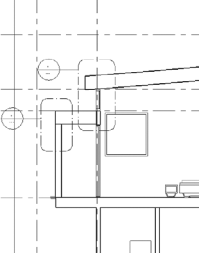
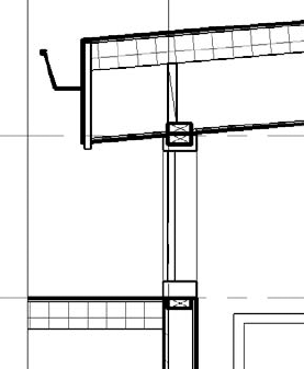
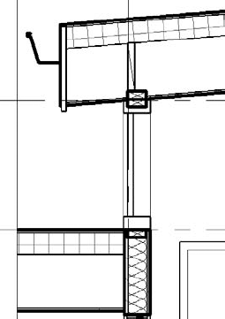
Open the Second Floor Plan view, and cut a wall section through the west end of the house, as shown in Figure 11.1. After creating this section, it will be pointed in the wrong direction. Using the Flip icon, flip the section cut to point in the other direction.
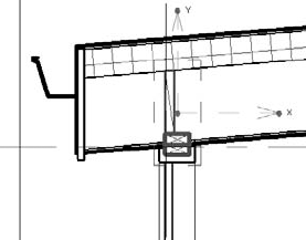
In the Section 3 view, create two callout views using the Callout tool located in the Create panel of the View tab. One callout should focus on the south clerestory condition, and the other should focus on the northern window in the stairwell. See Figure 11.2 for callout locations. Rename the details you have just created Detail 1 and Detail 2.

Note
To reposition the callout tag, select any of the callout lines and use the blue grips to reposition or resize the tag or the box.
Now that you have created the views needed to document your project clearly, you can begin laying them out on sheets. There is a sheet template located on the book's web page, www.sybex.com/go/introducingrevit2010; we will use it as the basis for our sheet set. You need one sheet for plans; one for elevations; and one for details, sections, and 3D views. To use the sheet templates and create the sheets, follow these steps:
Right-click on Sheets in the Project Browser, and select New Sheet from the context menu. In the next dialog box, choose Load and browse to the file named
Sheets-CD.rfa. Click OK.The Sheet view will become your active view. Repeat this step two more times, so that you have three sheets in the project.
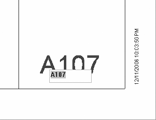
Rename the sheets as follows: A100 Floor Plans, A200 Elevations, and A300 Sections & 3D views. To do this, right-click the sheet name in the Project Browser and choose Rename to bring up a renaming dialog box. You can also rename the sheet directly in the view when the sheet is opened. Select the sheet and click the blue text of the sheet name or number, and the text becomes an active text field you can then edit. Be sure to change the sheet name as well as the sheet number when you're editing from the sheet itself (Figure 11.3).
When you add sheets, they appear in the Project Browser under the Sheets node.
As a next step we can begin adding views to the sheet itself. With a sheet view opened, you can drag a view from the Project Browser onto the sheet. Here's how:
In the Project Browser, select a view (click and hold on the view name), and then drag it onto the sheet. A preview graphic of the view extents appears to aid in placement.
When you get the view approximately where you want it, release the mouse button. The view drops into place.
Each view is assigned a unique number once it's placed on the sheet. This is referred to as the detail number, and it appears as a parameter of the view once it has been placed on a sheet.
For the next exercise, lay out the sheets with the following views on them:
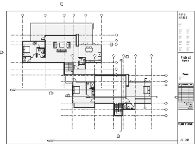
A100 — First floor plan and second floor plan. These views won't initially fit on the sheet, but we'll fix that soon enough.
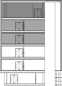
A200 — North elevation and south elevation.
A300 — Section 1, Section 3, and 3D View 1. Notice that on sheet A100, the two plans don't fit on the sheet; see Figure 11.4. Obviously, it's vital to be able to produce drawings that read clearly and easily within the bounds of what will be the printed area. Revit provides control over the sizes of your views as they appear on the sheets, so it's easy to fix issues like this when they arise.
You can do this directly from the sheet, giving you real-time feedback about the view and its relation to the sheet.

Open Sheet A100. Mouse over one of the views on the sheet, and right-click.
Select Activate View.
Use the View Control bar to select Show Crop Region (

Finish laying out the other two sheets. A200 and A300 should look like Figures 11.6 and 11.7, respectively.
Note
To make minor adjustments to a view location, select the view and use the arrows on the keyboard to nudge it around. The tighter you're zoomed in on a view, the smaller the increment of movement.
In a typical, professional-looking sheet arrangement, especially when you have multiple views (plans or elevations) on a sheet, it's common to line up gridlines (in the vertical dimension on the sheet) and levels (in the horizontal). Revit automatically aligns the grids and levels between views on the sheet when you drag views onto a sheet. Click and drag a view — a green, dotted snap-alignment line appears when grids are aligned with grids in the other views (or levels with other levels). This comes in handy when you lay out a sheet with multiple wall sections and you want the levels to all be lined up relative to one another on the sheet.


In Chapter 3, "Views," we explained that schedules are a live, textual view of the model. We also discussed the different types of schedules you can create and walked through a simple example. For your documentation, you need to know how to modify the graphical appearance of a schedule and filter out information you don't need to show.
When you create a new schedule, you're presented with a number of format and selection choices. These let you organize and filter the data for display in the schedule as well as set the font style and text alignment. Let's explore the options in the New Schedule dialog box.
Note
Revit is essentially a database of model objects that are loaded with information; thus many of the same functions available in database queries are available in Revit. If you're unfamiliar with database conventions, don't stress — you don't need to know about databases to run Revit successfully.
From the View tab in the Create panel, choose Schedules, then Schedules/Quantities to create a new schedule. The New Schedule dialog box (Figure 11.8) first prompts you to select the category of elements you want to schedule. You can provide a name for the schedule and choose which phase of construction the schedule represents. We've left the phase as New Construction, because that is what you're creating with the sample model.

Once you select the schedule you would like to create, you will be presented with another dialog box that contains the following tabs. These tabs are designed to help you format your data and its visual presentation:
- Fields
This tab lets you select the data that will appear in your schedule. For the wall schedule, it shows all the properties available in the wall family.
- Filter
This tab allows you to filter out the data you don't wish to show. You'll use this tab to restrict displayed data so that only information about the concrete walls in the project appears in the schedule.
- Sorting/Grouping
This tab lets you control the order in which information is displayed. It also allows you to decide whether you want to show every instance of an item or only the totals for a given family.
- Formatting
This tab controls the display heading for each field and whether the field is visible on the schedule. It's possible to add fields that are necessary for calculations or sorting but don't show on the printed copy of the schedule. Additionally, this tab can tell Revit to calculate the totals for any of the fields.
- Appearance
This tab controls the graphical aspects of the schedule, including the font size and type of text for each of the columns and headers in the schedule. It also allows you to turn the grids on and off or modify the line thickness for the grid and boundary lines.
The following example walks through the various options in the Schedule Properties dialog box while you create a new wall schedule. In this example, you'll create the schedule, filter out all but the concrete walls, and calculate the volume of recycled content in the walls based on the assumption that you're using 15 percent recycled content in all the concrete poured on the project. When you've finished, the schedule should look like Figure 11.9.

Follow these steps:
Open the
Station.rvtfile found in the Chapter 11 folder on the book's companion web page.Navigate to the View tab, and from the Create panel choose Schedules and then Schedule/Quantities.
Choose Walls from the category menu, and name the schedule Concrete Walls (see Figure 11.10).
Click OK.
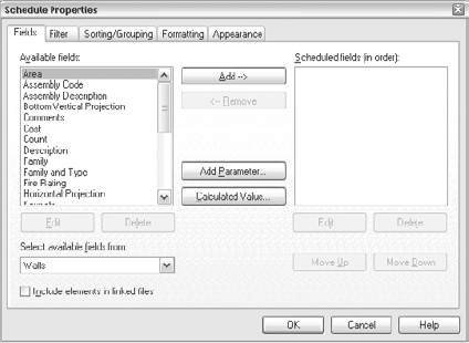
Select the fields to be scheduled (see Figure 11.11). The fields are parameters used by the category, and they all appear in the properties of the element being scheduled. Add a field by double-clicking the name of the field in the left pane or by selecting the field and clicking the Add button. Doing so moves the field from the left to the right column. Or, you can remove a field by selecting it in the right column and clicking Remove.
Choose the following fields for the schedule:
Area
Description
Family and Type
Length
Volume
Width
With a field selected, use the Move Up and Move Down buttons in the lower-right corner of the dialog box to sort the fields in the order you want them to appear in the schedule table. For example:
Family and Type
Description
Width
Length
Area
Volume
Note
There is no predefined field in Revit for recycled content, but Revit lets you create custom fields and custom formulas.
To make a new field to display information about the recycled content of your walls, click the Calculated Value button.

To make a new field to display information about the recycled content of your walls, click the Calculated Value button.
The Calculated Value dialog box opens (Figure 11.12). In this dialog box you can create new columns in your schedule based on relationships to other fields in the table. Name your new value Recycled Volume. For Type, choose Volume from the drop-down list, and in the Formula box, type Volume*.15.
When you're done, click OK.
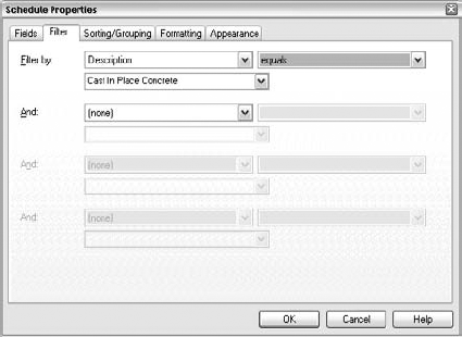
Choose the Filter tab (Figure 11.13). Because you want to show only the concrete walls, you need to filter out all the other walls in this schedule.
From the upper-left Filter By drop-down menu, choose Description.
The right Filter By menu allows you to select from a standard list of database queries: equals, doesn't equal, contains, doesn't contain, and so on. For this schedule, use the default value, which is equals.
From the lower-left Filter By menu, choose Cast in Place Concrete. (This menu dynamically generates from the descriptions given in the properties for the element in question. In this example, wall properties are displayed.)
Select the Sorting/Grouping tab shown in Figure 11.14. Use these options to sort the walls first by Family and Type, and then by Volume.
Near the bottom of this tab, select the Grand Totals check box. Choose Counts and Totals from the drop-down menu at the right.
At the bottom of this tab is an Itemize Every Instance check box. Leave it deselected for now. This makes it a hidden field.
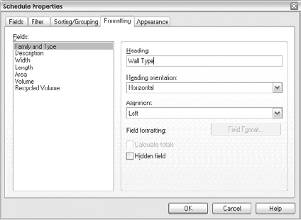
Select the Formatting tab shown in Figure 11.15. Change the Heading value of the Family and Type field to Wall Type. To do this, select Family and Type in the Fields list, and type Wall Type in the Heading box.
Note
On this tab, choosing Counts and Totals means you're telling Revit to auto-calculate a few things. First, you're counting all the instances of a type family in the model. You also have the option to report totals for those counted types. For example, you may have two sizes of fixed windows in a project. The count tells you how many of each type you have. The total gives you a sum of all the fixed windows, regardless of size. This count and total relate only to family or type quantities.
Select Description in the Fields list, and select the Hidden Field check box.
Select each of the remaining fields (Width, Length, Area, Volume, and Recycled Volume), set their alignment to Right, and select the Calculate Totals check box. This option tells Revit to add a list of other values together that aren't type related (like the calculation in step 15). This gives you the ability to calculate values between similar fields within Revit and return customized but accurate data. So, in English, this means that you can customize your schedules in a variety of ways and know that they are always reporting accurate and current information.
Note
You can select fields individually, or you can select them all by holding down the Ctrl key and clicking each field name.
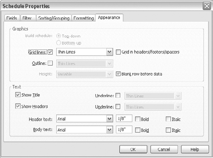
Select the Appearance tab shown in Figure 11.16. On this tab, you define gridlines, outlines, header text, and body text. Select the Bold check box to the right of Header Text. The rest of the settings are fine, unless you feel like experimenting with fonts and size.
Click OK. Revit will generate a schedule that shows all the information you asked for from the model. At the bottom of the schedule, the total for each of the fields is displayed.


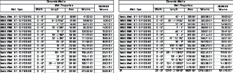
You can do some additional formatting after you create a schedule. By selecting multiple headers, you can group them and add secondary tier headers. Let's combine Width, Length, Area, and Volume:
Click in the Width header. Holding down the left mouse button, drag your cursor to the left or right, selecting additional headers until you've selected all four (see Figure 11.17).
Click the Group button on the Options bar.
Revit groups all four headers together. Add a title for the new grouping: Wall Properties (Figure 11.18).


Not only do Revit schedules report information about elements in the project but they also can be used to control elements. If you decide to exchange one wall type for another, you can do so by clicking in the schedule — under wall types, in this example. A menu appears, listing all available types currently in the model, and you can choose the type you want. Again, this automatically changes the instance of the wall to another wall type in all views in which the wall is present.
The schedule you just created lists all concrete walls; you can use the schedule to locate any of these walls in the model. To do this, select a wall from the schedule list. You can choose to highlight an element in the model and even delete the element using the contextual tab that shows up when a row is selected. Be aware that the Delete option entirely removes that element from the model and from every single view in which it appears. This is the essence of Revit: you don't need to manually seek all views in which this wall appears to delete it, because the element really exists once and only once in the model.
When you choose Highlight in Model, Revit opens any view the element can be displayed in, zooms in on that element, and highlights it in red. This powerful tool lets you find the location of any model element in the project.
The schedule is not only filled by rows automatically generated by the tool; you can also add new rows to the schedule manually. There are many cases in which this might be useful, such as when you make room schedules and you want to predefine room names before adding the tags to the model.
Note
Coordinated documentation is a key value of Revit. After you create a schedule, it doesn't require manual updating. Any time you add or remove content from the model, the schedule dynamically updates itself, even if it's placed on a sheet. A change you make anywhere in the model will be propagated everywhere that change is relevant.
Revit allows you to save a schedule that you've carefully prepared as a view template and apply it to other schedules. This is useful in cases when you have many schedules in a project and you need them to look alike to maintain visual continuity by using the same font and graphical conventions. To create a schedule view template, right-click the schedule in the Project Browser, and choose Create View Template From View. Then give the template a name.
The Schedule View template allows you to standardize all the font types, styles, and any other settings found on the Appearance tab in your schedules. Maybe you've already created schedules using various graphical styles. It's never too late to apply a view template and tidy things up. To apply a schedule template to a previously created schedule, follow these steps:
Right-click the schedule in the Project Browser, and choose Select Apply View Template.
Select the template you wish to apply, and click OK.
To place a schedule on a sheet, follow the same steps you used to place a view on a sheet. Drag and drop, and then adjust and nudge until you get the correct layout. Once you've placed your schedule on a sheet, you can start to take advantage of Revit's productivity tools.
Traditionally, schedules have been time-consuming and extensive exercises in data entry and table manipulation. Schedules are often long lists that are hard to manipulate and that need to be updated whenever new content is added to a project. Few applications have an intelligent way of doing all this. For example, splitting a schedule usually requires cutting, copying, and a lot of rework to achieve the needed appearance and coordinate the data. Revit makes this process easy by putting graphical controls directly onto a schedule once it's on a sheet. Click the Split icon (
Let's practice by placing a schedule on a sheet in the Station.rvt file where you created the Concrete Wall schedule:
Create a new sheet by right-clicking the Sheets group from the Project Browser and choosing New Sheet.
Select the Presentation: Presentation sheet.
Drag the Concrete Walls schedule from the Schedule list in the Project Browser onto the sheet in the View window.
When you drop the schedule onto the sheet, it appears too long for the sheet; the text in each cell is returned and wrapped in the cell, further adding to the schedule length (see Figure 11.19). This isn't the look you're aiming for. To modify it, grab the blue arrows at the top of the schedule header, and drag them to the right to enlarge the width of each column. Doing this makes the schedule wider and also shortens the column.
Unfortunately, even though the column has been shortened, it still doesn't fit on the 11″×17″ sheet you've placed it on. Fortunately, Revit lets you split a schedule into multiple segments. To do this, click the blue squiggle that appears in the center of the schedule on the left or right side (shown in Figure 11.20). This splits the schedule in the center and adds a new header to the new column.
Note
You can split a schedule as many times as needed to fit it onto a sheet.
To finally locate the schedules on the sheet, you can drag each set of columns independently by grabbing the blue cross icon in the center of the schedule. (These individual segments can't be placed on separate sheets.) The finished schedule on the sheet should look like Figure 11.21.


In addition to letting you split a schedule into separate segments, Revit allows you to rejoin the segments into a single schedule:
Select the blue cross at the middle of the second segment.
Drag it over the first segment of the schedule. Your schedule is complete and displays in its original form.
Because it isn't feasible, or even reasonable, to model every single construction detail in 3D, Revit provides the means to draft 2D information. Revit's drafting views are strictly 2D views used for drawing details for a construction document set. Some examples where it might be useful to move from the 3D model to 2D geometry are for things like window jamb, head, and sill details, or for reusing details taken from past projects, or from manufacturers who supply details in 2D. In our own practice, for teams just starting with Revit, it's a good rule of thumb to figure on creating any drawing at 11/2″ = 1′-0″ or larger as only 2D. This will give you some flexibility starting out in Revit to fine-tune your family making skills.
When placed on a sheet, drafting views have the same intelligent referencing as other views. This lets you produce coordinated drawings. Even though drafting views present only 2D details, because they're in Revit they can be tied parametrically to sheets, so all the references are dynamic.
To create a new drafting view, follow these steps:
Go to the View tab, and from the Create panel choose Drafting View (

A dialog box opens prompting you for a detail name and scale (Figure 11.22).
Using the Scale drop-down menu, choose from a list of standard and custom view scales.
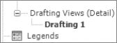
Click OK. A new node, Drafting Views (Detail), is added to the Project Browser (see Figure 11.23). This new drafting view is primed for either drafting a new detail or importing existing CAD details.

The drafting tools available in Revit are similar to what you might find in any CAD application. You can draw lines, arcs, and circles and create groups of 2D lines to use repeatedly. Lines can be drawn, extended, moved, copied, mirrored, arrayed, and trimmed — everything you'd expect to be able to do to lines. These can all be found on the Detail panel in the Annotate tab.
To demonstrate Revit's drafting tools, you'll work on the house model (from the book's web page, www.sybex.com/go/introducingrevit2010) for the remainder of this chapter. Open the file Source_House.rvt, and find the Detail 2 view that you created earlier. This is the detail through the window at the clerestory.
Several different drafting tools are available in Revit. You access them from the bottom of the Annotate ribbon (see Figure 11.24). We'll explore them here.


Note
If you're drawing something with lines that represents an object, consider creating a detail component.
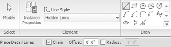
Figure 11.26. The Element and Draw panels contain all the line styles and shapes for drawing Detail Lines
If no existing line style conforms to your needs, if you want to edit the graphic properties of a line style, or if you want to delete existing line styles, use the Line Styles dialog box (from the Manage tab in the Project Settings Panel choose Settings and then Line Styles).
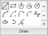
The Draw and Elements panels show all the drawing styles and line-shape choices available in Revit (Figure 11.26).
The Draw and Pick Lines tools are similar to the tools used to create walls. Draw (the default tool) allows you to choose any of the drawing options from the nearby button menus.
The Line tool (also selected by default) is the most commonly used tool. It's illustrated in Figure 11.27. The Draw panel to the right shows the array of tools you can use in Revit to create linework. We will briefly touch on each of these:
- Line
This is a simple line-creation tool. By default, when you choose the second point of your line, Revit automatically begins a new line from that point. You can disable this feature by deselecting the Chain check box on the Options bar.
- Rectangle
This tool draws all four sides of a rectangle or square. It can only draw vertical and horizontal lines.
- Inscribed Polygon
This tool draws multisided shapes from an inside dimension. When this tool is selected, a box on the Options bar lets you select the number of sides you want for your shape. If you want a rectangle that is nonorthogonal, use the Polygon tool and enter 4 for the number of sides.
- Circumscribed Polygon
This tool draws multisided shapes in a similar fashion as the previous tool but using an outside dimension.
- Circle
This tool draws circles by radius.
- Arc Passing Through Three Points
This tool draws an arc using the following sequence of points: first point, last point, midpoint.
- Arc from Center and End Points
This tool draws an arc using the following sequence of points: center point, start point, end point.
- Tangent Arc
This tool draws an arc from a starting point. You must select a point in the view to begin the tangent arc.
- Fillet Arc
Selecting this tool prompts you to choose two nonparallel lines and create a fillet arc between them.
- Spline
This tool draws a spline. The points of the spline can be edited after the line has been drawn, but you can't fillet or trim a spline.
- Ellipse
This tool draws ellipses by letting you locate the center and then the major and minor radii.
- Partial Ellipse
This tool draws a half segment of an ellipse using the following sequence of points: start point, end point, radius.
- Pick Lines
This tool allows you to draw lines on top of other lines or other elements simply by selecting them. This is a handy way to trace roof overhangs or other elements.
The Model Line tool (
Model lines are model elements (as opposed to detail/annotation elements) and appear in every view applicable. This means if you draw a line in an elevation view, it appears in every 3D view, elevation view, detail view, and so on, where that portion of the elevation is visible. The lines use all the same draw commands as the Detail Line tool; however, they're drawn on a 3D work plane in the model.
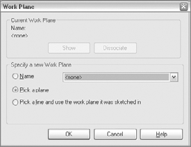
If the view you're in isn't an active work plane, then when you select the Model Line tool it will ask you to define or select a work plane by displaying the dialog box shown in Figure 11.28.
Here, you can use the Name option to choose a work plane that is already defined, use the Pick a Plane option to choose a face (such as the face of a wall or floor) to draw on, or use the Pick a Line and Use the Work Plane It Was Sketched In option, which we hope is self-evident.
Note
You may be wondering, "When do I use Model Line, and when do I use Detail Line?" Use Detail Line when you're drawing things in 2D that will appear only in the view they're created in. Some examples are linework in an elevation or something drawn in a drafting view. Use Model Line when you want the same line to appear in all views but you don't necessarily need a 3D modeled element to communicate the design intent. Examples for the use of lines are control joints or gaps between panels in a façade.
Note
Keep in mind that if a line occurs on a predictable module, it may be helpful to create a filled region.
Detail groups are similar to blocks in AutoCAD. They're collections of 2D graphics that you want to use repeatedly in the same or different views within the project. A classic example is a metal stud or wood blocking. You can easily and quickly set up a group and use that group over and over in the model. Doing so helps control consistency throughout the drawing.
To make a detail group, create the detail elements you'd like (make sure they are 2D elements), select all the elements, and then group them by using the Group command in the contextual tab that appears when detail elements are selected.
Once a group is created, you will be prompted for a group name. We suggest that you name the group rather than accepting the default name Revit wants to give it (Group 1, Group 2, and so on).

To place a detail group, use the Detail Group button in the Detail panel of the Annotate tab (
Detail components represent various small-scale building components such as screws, blocking, or metal studs, and are parametric 2D families. They're similar to detail groups, but are created in the Family Editor, and can be designed with dimensional variation built right into the family. In other words, a single detail component can make a full range of shapes available in a single component. Because they are families, this also means they can be stored in your office library and shared across projects easily.
To add a detail component to your drawing, select the Component button found on the Annotate ribbon and choose one from the Type Selector.

If you need to load a new component, click the Load Family button on the Place Detail Component ribbon, and browse to the Detail Components folder. Revit has a wide range of common detail components in the default library.
To make a new detail component, use the Family Editor, choose the Application button, and select New → Family → Detail Component.rft. Now you can begin drawing using drafting lines, as you did in the project, and then save the file as an independent family that can be loaded into any project as a detail component. We'll go into more depth on how to make families in Chapter 13, "Advanced Topics."
Note
A detail component is an incredible feature, not to be underestimated. Not only can you insert detail components into a project, but you can also insert them into 2D and 3D families and set them to show only at fine levels of detail. One way to use a detail component is to insert it into a family and use it to demonstrate a higher level of detail when the family is cut in section. An example is the shims and silicone in a window head that you don't necessarily want to model, but that you do want to show in a wall section or detail.
A masking region is designed to hide portions of the model that you don't want to see in a given view. A Masking Region imposes a 2D shape on top of the model that masks elements behind it.
Note
The masking region obscures only the model and other detail components. It can't mask annotations.
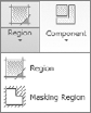
To add a masking region to your view, go to the Annotate tab, and from the Detail panel, select Region and choose Masking Region.
This takes you to Sketch mode, where you can draw a closed loop of lines to form a masking region. When you draw a masking region, you can assign the boundary lines different line styles — check the Type Selector to make sure you're using the line style you want displayed. One of the line styles that is particularly useful for the Masking Region tool is the Invisible Line style. It allows you to create a borderless region — ideal if you want to truly mask an element in the model.
Each line can be given its own line style, making it possible to create a shape with different boundary line representations. A masking region is shown in Figure 11.30.
To edit a masking region, select the region, and choose the Edit button from the Modify Detail Items ribbon. Doing so brings you back to the Sketch mode and lets you edit the region.
Now that you have a better understanding of detail components and masking regions, let's make an example on the model we have been using. You will be adding a gutter to the roof.
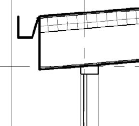
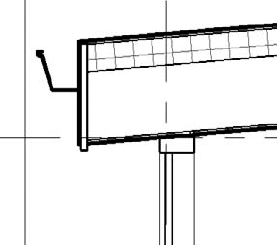
Select the Detail Component button, and choose the 4″×4″ gutter that has been preloaded into this model.
Open the view Detail 2, go to the View tab, and from the Detail panel select Component, Detail Component, and choose Gutter Bevel Section 4″ × 4″ (15 cm × 15 cm) from the Type Selector.
Use the Mirror tool to flip the gutter. Be sure to uncheck Copy on the Options bar. After mirroring the gutter, align it with the roof edge (Figure 11.31).
You also need to add a fascia board, which is something you didn't model with the Roof family. But before you do that, you need to mask some of the rigid insulation in the roof in order to build the fascia board back in from the roof edge:
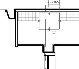
Use the Masking Region tool to draw a box at the roof edge. Make the box using four Medium Lines, and draw it 1″ (2.5 cm) wide. Bring it to the underside of the roof sheathing, and run it just past the bottom of the soffit, as shown in Figure 11.32.
Use the detail component Nominal Cut Lumber-Section 2×4 to build out the window heads. You can use the spacebar to rotate the component during placement.
Although you could use a detail component to place blocking above the window head, let's use the Detail Line tool instead. Select the Detail Line tool and a Medium Line from the Type Selector.
Draw a box from the window head to the bottom of the rigid insulation.
Using a thin line, draw a line from corner to corner in the box. The finished detail looks like Figure 11.33.
If you decide to move or change those lines you've just drawn, you want them to all move together. This is a great use for groups. By selecting the window head and the blocking, you can use the Group command to group those elements into one unit. Another way to group a selection of elements is by using the Model Group button located in the Model panel of the Home tab. Figure 11.34 shows the elements grouped together.
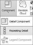
You create repeating details in Revit by going to the Annotate tab, and from the Detail panel select Component and then Repeating Detail.
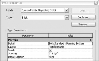
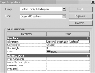
This tool takes a single detail component and arrays it along a straight line at regular intervals. Let's open the properties of a repeating detail to get a feel for how it's laid out. Figure 11.35 shows the Type Properties dialog box for a brick repeating detail.
When you select a repeating detail, the Type Selector is activated so you can select any repeating detail you've already loaded in the project. Repeating details are similar to families in that they have types and properties. If you don't have the repeating detail that you want loaded, it's easy enough to create one on the fly. All you need is a detail component that you wish to repeat.
Repeating detail placement is similar to placement of a line — the repeating detail has a starting point, an end point, and repeating 2D geometry in between. Let's make one to demonstrate this feature:
From the Annotate tab in the Deatil panel, select Component and choose Repeating Detail.
Choose the Element Properties button.
Click Edit Type.
Now, you need to select a detail component from the Revit library or use one you created on your own with the Detail field in the Type Properties dialog box.
The default repeating detail in Revit is a running brick pattern. If you look at it carefully, it consists of a brick detail component and a mortar joint (see Figure 11.36).
When you create a repeating detail layout, measure the distance between the beginning of the brick and the end of the mortar joint to understand the module on which the detail will repeat. When the detail component is inserted, it acts like a Line tool and allows you to pull a line of brick, as shown in Figure 11.37. This line can be lengthened, shortened, or rotated like any other line.


Note
If you're making a repeating detail from a component that isn't loaded in your project, you won't find it listed under the Detail item in the Properties dialog box. You first need to load it in your project and then make it a repeating detail component.

Let's take a closer look at the various options you can set in the Type Properties for a repeating detail (Figure 11.38):
- Detail
Here you can select the detail component you wish to have repeated.
- Layout
This option offers four different modes:
- Fixed Distance
The path drawn between the start and end points when drawing the repeating detail is the length at which your component repeats at a distance of the value set for spacing.
- Fixed Number
Here you can set how many times a component repeats itself in the space between the start and end points (the length of the path).
- Fill Available Space
Regardless of the value you choose for spacing, the detail component is repeated on the path using its actual width as the spacing value.
- Maximum Spacing
The detail component is repeated using the set spacing, and the number of repeated components is set so that only complete components are drawn. Revit creates as many as will fit on the path.
- Inside
This check box adjusts the start point and end point of the detail components that make up the repeating detail.
- Spacing
This value is active only when Fixed Distance or Maximum Spacing is selected as the method of repetition. It represents the distance at which you want the repeating detail component to repeat. It doesn't have to be the actual width of the detail component.
- Detail Rotation
This allows you to rotate the detail component in the repeating detail.
You can use the Detail Component tool to create custom line types (lines with letters or numbers for various services such as fireproofing, rated walls, fencing, and so on). Note that when you create a detail component, you can't use text for the letters but need to draw them using lines.
Figure 11.39 shows the creation of a detail component in the Family Editor and the final result used as a repeating detail in the project environment.
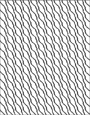
The Insulation tool (
- Width
This parameter is used to control the width of the insulation that is used. The Width parameter is also available on the Options bar when insulation is selected and is specific to each instance of insulation added to the model. Changing the width of one instance of insulation will change only that instance (see Figure 11.40).
- Insulation Bulge to Width Ratio
This parameter is used to control the density of the circles used in the insulation line, making the circles for the insulation head wider or flatter.
In most cases, you'll have two lines representing the space in the wall where the insulation needs to fit. Revit allows you to place the insulation using the centerline of the insulation as a location line.
Now, let's add some insulation to your detail:
Select the Insulation tool located on the Detail panel of the Annotate tab.
In the Options bar, set the width to 31/2″ (10 cm).
Draw in the insulation below the windowsill. The finished detail will look like Figure 11.41.

It can help you color surfaces or areas for graphic representations during the conceptual or design-development phase. It also can be a useful tool to document details and show material texture. Figure 11.42 shows how filled regions are used to communicate different functional zones in section.
A filled region consists of a boundary, which can use any line type, and a fill pattern that fills the area defined in the boundary. Figure 11.43 shows a filled region used with a hatch pattern.
Filled regions can also be transparent or opaque to show or hide what is behind them. Figure 11.44 shows two filled regions: the one at left is opaque, and the one at right is transparent.
Filled region type properties define how the fill appears. This includes pattern, pattern color, and transparency (see Figure 11.45).
Should you want to change the line style of the region boundary, you need to edit the region and then change the line style in Sketch mode. The Edit Boundary button appears on the Modify Detail Items ribbon when a filled region is selected.

For each filled region that has a different pattern, transparency, or other variation in appearance, you need to make a new filled region type. Remember that type properties propagate to all instances within the model, so making a change to one type may affect many instances in many different views. If you want to make a filled region with a new pattern, be sure to duplicate an existing type before you start changing type parameters (unless, of course, you want them all to change).
Revit lets you define different line styles for each boundary segment of a filled region. This can be handy depending on how you're using the filled region. For example, if you're using the filled region with an earth hatch to cover the foundation, you might want a heavier line around the footings and slab and a lighter one in other areas.
The effective use of filled regions depends on the fill patterns used in them. Let's review in more detail some basic aspects of fill patterns:
Fill patterns can be drafting or model patterns.
Drafting fill patterns are visible only in the view in which they're created. Drafting view fill patterns are scaled specific to the view. So, a pattern with ¼″ cross-hatching will always show with the lines ¼″ apart, regardless of the scale of the view.
Model patterns represent the material characteristics of an element (brick, stone, and so on) and do appear in 3D view. These patterns are model based and will not change their dimensions based on scale. So, if you have a standing-seam, metal-roof pattern of vertical lines 16″ apart, they will always measure 16″ apart. In a ¼″-scale view, they will print twice as far apart as in a ⅛″-scale view.
Note
Revit comes with a nice selection of both drafting and model patterns, but, as with any library, it's never enough. You'll often want to create patterns or reuse patterns from other projects or applications. Patterns can be imported from any AutoCAD .pat files as well. Specify whether the pattern is model or drafting.
Show/Remove Hidden Lines
In visual communications between architects and engineers, when one element obscures another, either partially or fully, the hidden element is usually represented with dashed lines. Often, just a portion of an element is hidden. In the CAD world, it can take a lot of work to explode a block, split lines, and change many of the line styles to a hidden line type.
Revit has a special tool, called Show/Remove Hidden Lines, for recognizing obscured elements and representing the portion that is hidden with dashed lines while still maintaining the complete object. This tool isn't located on the Annotate tab; it is a part of the Modify tab (see Figure 11.46).

Figure 11.46. Show Hidden Lines tool
You select the Show Hidden Lines tool, click the element that obscures the object, and then click the element that is obscured. The hidden portion of the element becomes dashed. If an element is obscured with more than one element, keep repeating this operation until you get the desired look. Because Revit is a parametric engine, when you relocate or delete the obscuring element, the hidden element responds intelligently to those changes.
The first image in Figure 11.47 shows an I-beam hidden by another beam. The second image shows the results after the first iteration of the Show Hidden Lines tool, when the second beam is selected as an obscuring element and the I-beam is selected as an obscured element.
The Show Hidden Lines tool applies to 2D and 3D elements in all possible combinations (detail over detail, detail over model, model over detail, model over model).
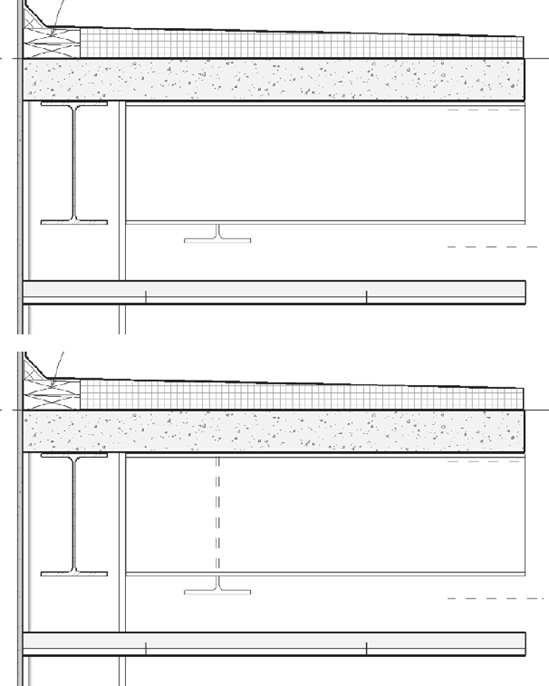
Figure 11.47. Using the Show Hidden Lines tool
Beneath the Show Hidden Lines tool is the Remove Hidden Lines tool, which resets the graphic display of the elements so they look like they did before you applied the hidden line mode. This is the lower button in Figure 11.46.
In Chapter 7, "Working with Other Applications," we discussed how to import a CAD file into Revit. Existing libraries of CAD details or details you receive from a manufacturer can also be imported directly into a Revit project. If you're working with someone who only produces details using CAD, you can incorporate their work into your Revit model without disrupting workflow.
To prepare a CAD file for import, we recommend that you delete all the superfluous data in the file before importing. If your import contains hatches or annotations that you don't intend to use in Revit, delete them first as well in the application where they have been created (AutoCAD, for example).
We also recommend that you import only one detail at a time so you can take better advantage of Revit's ability to manage sheet referencing. If you have a series of details organized in a single CAD file that you'd like to import into Revit, save as one separate file in order to isolate each detail, and then import them into separate drafting views within Revit.
There are many times in a project workflow when you want to grab details made in other projects and reuse them. So far we have covered how to do this using CAD files from other projects and from manufacturers' websites. This workflow is also possible using details created from other Revit projects. We will also talk about how to take our active project file and export key details to our library. In this section, we will discuss how to pull details out of a Revit file and put them into our active project.
As you create more and more details in Revit, you will inevitably want to save some of them to your office's standard library so that you can reuse them in other projects and save the invested work. With Revit, you can save a view out of a project and create a separate .rvt file that contains only that view. That file can then be incorporated into new projects. For example, if you have a 3D model detail that you embellished with 2D components and invested time making it, and would like to save that work for future projects, you can save it as a Revit file.
Right-click any drafting view in the Project Browser and choose Save to New File. It might take Revit a minute or so to compile the view content, but soon you will be presented with a dialog box asking you for a file location to save the view. The default filename will be the same as the view name in the project. To bring views from that file into another project, open the other project, then choose Insert from File → Views from the Insert tab. Choose the file you saved. Soon a dialog box (see Figure 11.48) will open and you can choose which views to bring into your project.


Once the view is exported, it is like any .rvt file. Opening the view directly will allow you to edit and manipulate any of the elements you exported in the view. You will also see a streamlined version of the Project Browser (Figure 11.49) with only the relative views present. These Revit files can be kept in a project library for later use.
The second way to export a view from Revit is to choose the Application button and select Save As → Library → View. This will open a dialog box of all of the exportable views from the project file. Here, you can select any number of views to be simultaneously exported into separate library files (Figure 11.50). This is a great way at the end of a project to export all of the detail views you would like to keep in a project library. Select the desired views by checking the appropriate boxes and click OK.
To import any of these files into a new project, navigate to the Insert tab and choose Insert from File → Insert Views from File. This will allow you to navigate to your library containing your exported details. Choosing the exported detail file opens a dialog box (Figure 11.51) that allows you to select the view.

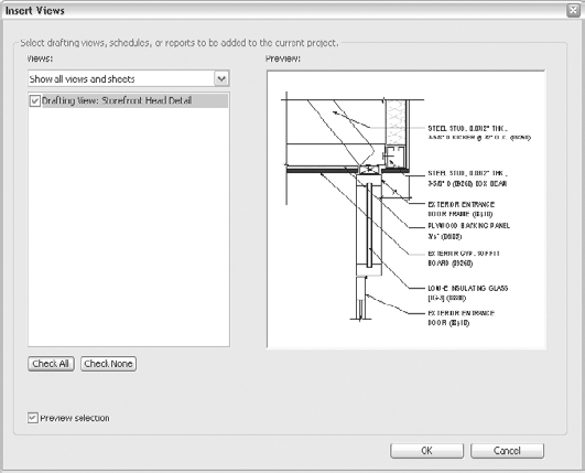
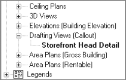
Notice that the view is described as its location within the Project Browser (Drafting View) and its view name (Storefront Head Detail). Selecting this view and clicking OK will merge the view into your current project (Figure 11.52). The view will appear in the location called out by the view name. In this case, you can find this view located in the Project Browser under Drafting Views.
Another way to insert content into Revit is to use only the drafting views from exported files and not import any of the model components. This can be useful in many examples where you might want to take a doorjamb detail or a window head condition. In these instances, the detail might be strictly 2D, so you aren't going to import any of the 3D model information. Or you might have a wall section where some of the elements are drawn in 2D and 3D. You might only want the 2D information (the drafting lines, detail components, and annotations, for example) because you plan to reuse those in a new section in a different project.
To import the 2D content into your view, open the view you want to import into and from the Insert tab choose Insert from File → Insert 2D Elements from File. The resulting dialog box will look similar to the one for importing the full view but with some slight differences (Figure 11.53).

Unlike with the Insert Views, you can only choose one view at a time to insert. There is also an option to transfer the view scale with the view elements. Selecting this check box will reconfigure the view you are inserting into to match the view that you have inserted.
Select the drafting view and click OK. This will bring all of the 2D elements in the selected view into your active view. You can repeat this command multiple times in the same view window if you need to repeat the content.