Class Diagrams
Representing the domain model for an application is arguably the most important area of object-oriented modeling. Class diagrams , as a result, are the most widely used feature of the UML.
Class diagrams show the relationships between classes in a system. Since object-oriented design blurs the line between data objects and executable application logic, a UML class diagram documents both. UML actually supports both class diagrams and object diagrams. If you’re reading this book, you’re almost certainly familiar with the distinction between a class and an object: a class is a framework containing methods and data that can be instantiated into one or more objects, which contain actual data items. UML class diagrams show the relationship between the frameworks, and object diagrams show the state of a system with actual objects, containing actual values.
Although the names are the same, a class in a UML class diagram does not necessarily map to a Java class—although in more detailed, design-focused UML diagrams, they will. Class diagrams can be used to build conceptual pictures of an application’s domain model, which can then be used to develop more specific system designs that eventually map into code.
It’s nice to be as complete as possible when developing a class diagram, but it is by no means necessary. Generally, a modeler picks a level of completeness that corresponds with the current stage in the software design process. The highest level class diagrams ignore all private methods and internal data structures, focusing instead on the logical content of the objects.
The diagram in Figure 2-6 illustrates a single class, in fairly high detail. The first compartment of the box holds the class name. The second compartment identifies the fields within the class, and the third compartment includes the methods in the class. In UML terminology, these are referred to as the attributes and operations of the class, respectively. Each of the fields and methods has a visibility modifier: +, -, or # for public, private, and protected. A colon and a variable type to indicate the storage or return types can follow both fields and methods.

With the exception of the top compartment, each section is optional. Some modelers leave all three compartments in place for clarity, while other modelers omit the middle (fields) compartment if they are modeling at a high level.
In addition to the class name, the class name compartment contains the «abstract» stereotype, indicating that the class is abstract. Since stereotypes modify whatever follows them, we put the «abstract» stereotype above the class name rather than below.
Relationships Between Classes
Aside from detailing the attributes and operations of particular classes, UML class diagrams can also indicate the relationships between classes. The two basic associations possible between classes are a dependency and a generalization . Dependencies indicate that a class makes use of another class as part of a data relationship. Generalizations correspond to class inheritance, much as we saw for use cases. Figure 2-7 shows a set of classes for an implementation of our user registration scheme.

The diagram above shows two key aspects of the association between
the UserDirectory and User
classes. The first is the navigability of the relationship, indicated
by the direction of the arrow. Drawing the arrow pointing from
UserDirectory to User indicates
that the UserDirectory has access to all
associated User objects, but that
User objects do not see the
UserDirectory they are a part of. The diagram also
indicates the multiplicity of the relationship between
UserDirectory and User via the
labels on each end of the association. The 1 next
to UserDirectory indicates that for any given
User object there is one
UserDirectory, while the * on the
User end indicates that there can be an unlimited
number of users in a directory.
There is a generalization relationship between the
User
class and the
CustomerUser
,
PartnerUser
, and
EmployeeUser
classes that extend it. Each class
defines distinct IDs for the user category as well as providing other
relevant methods. The customer class has a relationship with a
CreditRating object, which is not described in
detail on the diagram. When refining the picture to move towards a
more complete implementation, it makes sense to specify the kind of
associations possible between a Customer and a Credit Rating.
Associations and dependencies can also be labeled. In addition, each
class within the association can be assigned a particular role. The
association name is printed toward the center of the association
line, and the roles are listed on either side. General usage normally
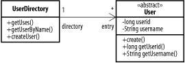
puts the name above the line and the roles below it. Figure 2-8 shows the UserDirectory and
User relationship again, but the
association has
been named Directory Link and the two objects have been assigned the
directory
and
entry
roles within the association.
Aggregation and composition
In addition to associations, UML provides constructs for representing aggregates and composites. Aggregates represent a “part of” relationship. While regular associations can be very loose, aggregates impose limits on the kinds of classes that can be included in the relationship, and the roles those classes can have. A customer may be associated with an order, but the order isn’t necessarily part of the customer, and the order can be associated with other objects and maintain its relevancy even if the customer record is destroyed. At the same time, an order line item is part of an order, so a stronger relationship than a mere association can be drawn. A line item has no meaning outside of an order, so we can define an order as an aggregation of line items, plus other information.
In Figure 2-9, the PartnerList
object is an aggregation of Partner objects. We
use an open diamond on the parent side in order to indicate that it
is an aggregate association, rather than a mere association.
UML defines an even stricter form of association, the composite aggregation , or simply composite. A composite relationship indicates that the subordinate objects are effectively part of the parent. When the parent object is copied, modified, or deleted, the subordinate objects should also be copied, modified, or deleted, as appropriate. The composite aggregation is indicated via a filled diamond on the association line next to the parent, as in Figure 2-10.
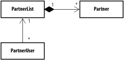
Figure 2-10 shows a PartnerUser
class associated with the PartnerList via
composite aggregation. If the PartnerList was
simply an aggregation, each PartnerUser class
could be associated directly with the relevant
Partner class (which presumably contains
information about the partnership relationship itself). In this case,
however, the PartnerUser must be associated with
the PartnerList instead, and it must use the
PartnerList class to interact with the
Partner data.
Describing Patterns with Class Diagrams
Throughout most of this book, we use UML class diagrams to talk about
patterns; here’s an example. Figure 2-11 shows an implementation of the Gang of Four
Strategy pattern. The Strategy pattern allows a client (in
this case, the StrategyRunner class) to perform an
action using different approaches determined by plug-in classes that
conform to a standard interface.
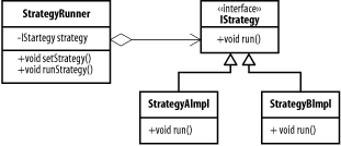
The StrategyAImpl and
StrategyBImpl classes both implement the
IStrategy interface, which includes a single
method, run( ). At runtime, the application
instantiates the appropriate strategy implementation and passes it to
the setStrategy( ) method of the
StrategyRunner, and then invokes the
runStrategy( ) method. In real life, strategies
could include persistence methods, cryptographic algorithms, message
transports, or anything that might need to be done consistently in
more than one way.
Objects
Class diagrams are static; they describe the relationship between classes but don’t show the state of a system at a particular time. Object diagrams can be used both to model the potential contents of a system and to gain a “snapshot in time” of the data that currently resides within a system.
An object instance is represented as a box, just like a class, but
the name is underlined. Objects are labeled as object
name:class name; the object name or class name may be
omitted. Omitting the object name indicates that the name of the
particular class instance is not relevant to the diagram.
The diagram in Figure 2-12 is fairly self-explanatory. The top compartment of the object contains the object name and class name, and the bottom compartments contain values for the fields. The lines between objects represent the associations. Associations do not need to be complicated. The presence of the objects themselves conveys most of the information about the types of associations that are permitted.

Packages
UML also provides a shape called a package . A UML package can be analogous to a Java package, or it can simply represent a group of classes with related functionality, regardless of underlying implementations. Creating packages within software projects is a good way to manage dependencies within applications, since the software can be dealt with in terms of the interfaces between packages rather than the interface between classes. This distinction makes it much easier to determine where changes to one area can affect others. Figure 2-13 shows a basic class diagram that documents the relationship between a Web Site, the Partnerships and Users domain objects, and three J2EE components. The servlets in the web site package depend on the J2EE servlets and JSP packages, as well as the JDBC package. They also depend on your own Partnerships and Users packages. The Users package also uses JDBC.
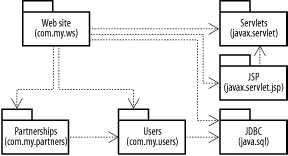
Note that there are no cycles in this diagram (Package A depends on Package B, which depends on Package A). While there is nothing in the UML to forbid cycles, recursive package dependencies generally reveal design and maintenance problems. When dependencies between packages loop back on themselves, it’s generally time to either change the software or change the diagram. Again, we don’t need a one-to-one link between packages on a package diagram and packages in the way we think of them in Java. Java packages are primarily a mechanism for code organization rather than design, and they generally interlock more than the design level packages in our diagrams.
Packages can also be nested. This ability allows you to draw dependencies to either individual packages or to higher-level packages. Figure 2-14 shows the same package diagram as Figure 2-13, but it creates high-level packages for both the J2EE components and the application domain. Dependency arrows that cross over package borders connect single packages, while arrows from a package to an outer-level package show dependencies to the entire outer package. In this case, the code within the Web Site package is dependent on J2EE and the application domain, and the Users package within the application domain is dependent only on JDBC.

When we nest packages, we put the label on the tab, rather than in the main compartment. Within individual packages, we can list the interior classes (or embed full class diagrams, although that’s unwieldy).