
Summary of Functionalities
This part focuses on the elements and functionalities in IEEE 802.16, both Legacy and Advanced, that dictate access network's operation. In what follows, we provide a detailed description of the different chapters and highlight—where applicable—certain features that characterize the IEEE 802.16 and its evolution.
Frame Structure
For both the Legacy and the Advanced IEEE 802.16, the details are provided for an OFDMA frame structure in both duplexing modes, that is, TDD and FDD. Descriptions for the frame structure operating in both the PMP and the MR modes are also provided. These details and descriptions are discussed in Chapter 4.
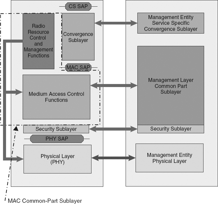
Figure 3.6 The IEEE 802.16m System Reference Model. Reproduced by permission of © 2009 IEEE.
The amalgamated IEEE 802.16-2009 document maintains the IEEE 802.16e descriptions2, allowing for different frame durations. In IEEE 802.16, the BS is the network entity generating the frame, and the one that assumes control of the frame's content for PMP operation. In the MR case, some control can be delegated to the RS, specifically, the ntRS mode where a RS can generate its own frame playing the role of a BS for all MSs associated with it. However, a tRS is always controlled by its superordinate BS. In this case the BS generates an access area and relay area in a frame.
To ensure backward compatibility with the IEEE 802.16-2009 frame structure, the IEEE 802.16m amendment describes a frame structure that achieves legacy support for IEEE 802.16 deployments, and enables the use of new PHY layer and MAC layer features. The amendment defines a 20 ms length superframe instead of a frame. A superframe is divided into four equally sized 5 ms frames to provide the low latency feature of IEEE 802.16m. Meanwhile, the superframe maintains the support for both TDD and (H-)FDD duplexing modes.
Network Entry
The detailed procedures for network entry, initialization and ranging for IEEE 802.16 are described in Chapter 5.
While network entry, initialization and ranging have distinct operational objectives, their procedures often overlap. Network entry means enabling a SS or MS to associate with an IEEE 802.16 access networks, while initialization involves setting up the elemental connection that would enable the SS to request useful data connections. Finally, ranging is the procedure by which these connections are established. Initial ranging is performed in the user's first entry to the network, while ranging itself is a basic network procedure performed by MSs as well as RSs.
The network entry and initial ranging involve different procedures through which MS connectivity parameters can be configured and primary connections can be established. Downlink synchronization is one of these procedures, during which the MS scans a list of downlink channels to find an active one. The MS synchronizes with a downlink channel by listening to the preamble of the frame transmitted by the BS. The synchronized MS starts of the initial ranging by sending a ranging request to the BS and awaiting a response. The request is sent with a robust modulation and a minimum transmission power. In the event of failure to receive a response, the MS increases the transmission power in an attempt to reach the BS. Once a response is received the MS adjusts its timing and power utilizing the information included in the response message. After a successful initial ranging, the MS informs the BS about its capabilities in a capability request message indicating useful information such as the MCS and the duplexing methods supported. Afterwards, authentication followed by registration takes place and the MS gets connected to the network by assigning it an IP address via the Dynamic Host Configuration Protocol (DHCP) and provide an address for the Trivial File Transfer Protocol (TFTP) server to download any necessary files. The last step is to establish provisioned connections.
Ranging is required at nearly all stages of MS operations to maintain connection quality. Ranging perform mid-connection is distinguished from the initial ranging and is called periodic ranging is the BS and the MS are periodically engaged in its execution.
In the IEEE 802.16m amendment, a concise state machine is defined for both a MS and a RS. This differs greatly from how the MS and RS operations were described up to and including the amalgamated IEEE 802.16-2009 document. In IEEE 802.16m, an AMS transitions between five distinct states; off, initialization, access, connected; and idle.
The network entry and initial ranging procedures are performed while an AMS is in Initialization and Access states. Periodic and other (e.g., for handover) ranging procedures are performed while an AMS is in a Connected state.
In the Initialization state, the AMS performs cell selection by scanning, synchronizing and acquiring the system configuration information before entering Access state. At the Access state, the AMS performs network entry by carrying out multi-steps include ranging, pre-authentication capability negotiation, authentication and authorization, capability exchange and registration. On the success of all of these steps, the AMS receives its Station ID and can now establish initial service flow and transition to Connected state.
When RSs are deployed, they follow similar procedures for connection initialization and maintenance. In addition, RSs may perform interference measurement of neighbor stations, path creation, and tunnel connection establishment with BSs. The RS supports the network entry of an access station by at least providing the initial link adaptation and the remaining network entry procedures may be processed between the MS and the BS in case of tRS.
QoS and Bandwidth Reservation
Quality of serving handling is extensively described in both the IEEE 802.16-2009 and its amendment, IEEE 802.16m. These descriptions are overviewed in Chapter 6 of the book.
In terms of connection-mode, the IEEE 802.16-2009 is designed based on a connection-oriented concept. Each connection is identified by a 16 bit connection ID, with data traffic transmitted over transport connections, while management messages are transmitted over management connections. Transport and management connections are unidirectional and associated to service flows that define the appropriate QoS constraints of the transport connection, and determine the level of treatment the MAC frame receives from the network.
To simplify the design of procedure that determine the level of treatment of MAC frames, IEEE 802.16-2009 specifies five different types of service classes to provide QoS for diverse types of applications.
- Unsolicited Grant Service (UGS): Supports Constant Bit Rate (CBR) services such as T1/E1 emulation and Voice over Internet Protocol (VoIP) without silence suppression.
- Real-Time Polling Services (rtPS): Supports variable size real-time data packets generated on periodic basis like Moving Picture Experts Group (MPEG) video or VoIP with silence suppression.
- Extended rtPS (ertPS): ertPS is a scheduling mechanism that has characteristics similar to both UGS and rtPS. It supports variable-size transport data packets, such as VoIP with silence suppression.
- Non Real-Time Polling Services (nrtPS): Supports delay tolerant services that require allocations on regular basis, such as File Transfer Protocol (FTP).
- Best Effort (BE) Services: supports BE traffic and provides little or no QoS guarantees such as web surfing over the Internet.
Bandwidth allocations in both, the downlink and the UPLINK, are exclusively managed by the BS. With data to send, the BS schedules the PHY resources required to meet the data QoS requirements on a per-connection basis. Allocations made to specific MS are indicated in the DL-MAP over dedicated management connections. A DL-MAP, as will be detailed later, is a map relayed in the frame to specify the allocations assigned for each MS in terms of both frequency and time slots. Except for UGS connections, a BS may increase or decrease a downlink connection's allocations at its own discretion, that is, to enact certain prioritization policies or to adapt to medium conditions.
For a MS to receive an allocation on the UPLINK, it must generate a Bandwidth Request (BR). A BR may be sent either in a dedicated BR PDU, or optionally piggybacked using the grant management subheader. A BR for a connection can also be incremental or aggregate. For incremental requests, the BS combines the new bandwidth requirements to those of the MS's currently active connection. Aggregate requests, however, are treated as a new view of the MS's total bandwidth requirement. While supporting the incremental BR is optional for SSs and mandatory for BSs, supporting aggregate BRs is mandatory for both. A MS requests bandwidth per connection ID, while the BS processes these requests on a per MS basis.
Naturally, a MS requires allocations in order to be able to send its BR. This process is called polling. BRs for non-UGS scheduling services can be sent using one of the following four methods.
- Unicast polling: (applies to SC, OFDM and OFDMA air interfaces) Each MS is individually polled by the BS.
- Multicast and Broadcast Polling: (applies to the SC and OFDM air interfaces) Used when there is insufficient resources to individually poll inactive SSs. The BS allocates transmission opportunities and indicates these allocations in the UL-MAP.
- Contention-based CDMA BR: (applies to the OFDMA air interface) An MS can use the ranging subchannel and contend using a BR ranging code.
- Poll Me (PM) bit: A MS with a currently active UGS connection can indicate that it needs to be polled for non-UGS connections through setting the PM bit in a PDU's Grant Management Subheader GMSH within its UGS connection.
In terms of traffic handling, the standard does not specify any requirements for traffic policing and shaping within an IEEE 802.16 network. As for scheduling, a scheduling algorithm for the UGS service (CBR) traffic, called persistent scheduling, is defined for OFDMA. Persistent Scheduling is a technique used to reduce MAP overhead for connections with periodic and fixed payload-size traffic. UGS resources are persistently allocated by the BS.
The IEEE 802.16m differs from IEEE 802.16-2009 by assigning each flow a four-bit Flow ID (FID). The FID can be combined with a 12-bit Station ID (STID) to generate a network-unique 16-bit identifier for the flow. The objective of introducing the FIDs is to decrease the latency of handover, since the FID does not need to change during handover. Hence, the connections are reestablished faster by just changing the STID from the servicing ABS to the new ABS. However, while IEEE 802.16m is limited to 16(= 24) connections per MS dictated by the four bits FID; IEEE 802.16-2009 supports up to 65536(= 216) connections.
Another distinguishing feature of IEEE 802.16m over IEEE 802.16-2009 is latency reduction by shortening the time needed to honor a BR. The IEEE 802.16m supports an enhanced BR mechanism, where the BR-grant process is reduced into three steps instead of the regular five steps, where step 2 and step 3 are bypassed for faster BR -grant procedure as shown in Figure 3.7.
In addition to the resource management procedures and classifications defined for IEEE 802.16-2009 and IEEE 802.16m, an IEEE 802.16 RS can operate in distributed or centralized scheduling. When a BS is configured to operate in centralized scheduling, the BS schedules all radio resources in its cell. In distributed scheduling, the BS and RS schedule the radio resource on their subordinate links individually. However, the RS produces its schedule given the radio resource assigned to it by the BS.
Mobility Management
A detailed account of IEEE 802.16 mobility management is described in Chapter 7. By definition, mobility management in IEEE 802.16 deals with realizing seamless mobility as users switch from one part of the network to another, regardless of the utilized access technologies. The standard supports both intra-RAT handovers (Legacy-to-Legacy, Advanced-to-Advanced, legacy-to-Advanced, and Advanced-to-legacy) and inter-RAT handovers (between IEEE 802.16 networks and other access networks such as LTE/-A, HSPA+, WiFi, etc.).

Figure 3.7 The bandwidth request mechanism in IEEE 802.16m. Reproduced by permission of © 2009 IEEE.
The intra-RAT handover is carried over two phases; network topology acquisition and handover execution phase. Even though the standard does not specify how the handover decision should be made, nor does it mandate whether the decision should be made by the network or the MS, the standard does provide means for information acquisition by both the BS and the MS to make efficient decisions.
The network acquisition phase consists of three steps: network topology advertisement, neighbor BS scanning and association process:
- Network topology advertisement is performed by the serving BS. The serving BS periodically broadcast advertisement messages to all subordinates to provide information about the neighboring BSs.
- Neighbor BS scanning: In this phase the MS acquire the serving BS to specify when and for how long the MS can perform measurements of the neighboring BSs received signal strength. After getting this information, the MS measures the received signal strength of the neighboring BSs after acquiring synchronization with each neighboring BS. After collecting the neighboring BSs measurements and other parameters, the MS decide whether or not a neighboring BS is adequate as a target BS.
- Process of association: This is an optional process, where the MS acquire ranging and service availability information from the neighboring BSs. The objective of this process is to decide on the most proper target BS and to expedite probable future handover.
The second phase is the handover execution phase. It consists of two stages:
- Handover preparation: In this stage, the MS sends handover request message, which includes the measured signal strength, if the neighboring BS received signal exceeds the threshold required for a handover decision. The serving BS communicates to the target BS the expected QoS level for the MS along with the resources required by the MS. The serving BS will choose the best target BS based on the replies received from all target BSs. Subsequently, the serving BS informs the MS by its decision to start the handover action phase.
- Handover action: In this stage, the MS continues the handover by sending a message to the serving BS confirming or cancelling the handover. If the MS decides to disconnect from the serving BS, it stops listening to the serving BS and starts network re-entry with the target BS. Next, it negotiates the basic capabilities, authorization and authentication, registration with the target BS. Moreover, it terminates its connections' context with the serving BS such as timers, counters, ARQ state-machine, etc. The latency of the handover (which is the duration of the handover action period) can be minimized by if the serving BS sends the MS information to the target BS. Consequently, the target BS can skip some steps of the handover action phase based on the type and the amount of information received from the serving BS.
The IEEE 802.16m supports both, network and MS assisted handover. The handover consists of three phases:
- Initialization: The Initiation phase is only necessary if the handover is being started by an AMS. In this phase, the AMS sends a handover request message to the serving ABS.
- Preparation: The preparation phase starts when the serving ABS sends the AMS information to the target ABSs. This information includes authentication and identification information. Subsequently, the ranging process between the AMS and each target ABS is performed. Based on the information gained by the AMS during the ranging process, the AMS selects a target ABS. Finally, this stage ends when the serving ABS sends control information to the target ABS. The control information indicates whether the handover is hard or soft, the target time of the completion of the handover process and the disassociation with the serving BS, and the AMS connections' information.
- Execution: This phase is similar to the handover action phase of IEEE 802.16-2009. It starts with the network re-entry procedure of the AMS to the target ABS and ends by the AMS disconnection from the serving ABS. If disconnection happens after finalizing the network re-entry, then the handover is soft, otherwise it is hard. Figure 3.8 shows the general handover procedure in an IEEE 802.16m network.
Besides the ABS to ABS handover, IEEE 802.16m defines three other types: R1BS to R1BS (legacy to legacy), ABS to R1BS (IEEE 802.16m to legacy), and R1BS to ABS (legacy to IEEE 802.16m). In addition, it supports handover from and into IEEE 802.16m Femtocells.
IEEE 802.16m defines handover procedures and signaling for handover from IEEE 802.16m network to other RAT (i.e., Inter-RAT handover) including LTE, IEEE 802.11, GSM/EDGE, 3GPP2, UTRA and CDMA-2000. Also, it supports the 802.21 standard for technology independent handover.
The handover in relay networks is not much different from IEEE 802.16-2009 and IEEE 802.16m. In relay network, the A/BS still carry out the scanning and network topology advertisement while the A/RS relays only the MAC control signaling such as the handover command message and indication message between the subordinate AMS and the ABS. If the handover is carried out between the ABS and the ABS's subordinate ARSs, that is, the AMS roams under the ABS, the AMS context information transfer can be omitted.
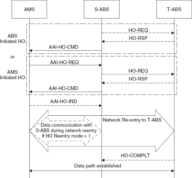
Figure 3.8 The general handover procedure in IEEE 802.16m. Reproduced by permission of © 2009 IEEE.
Security
Chapter 8 describes the robust security functions defined in IEEE 802.16. The functions include strong encryption and mutual authentication. The standard relies on a concept similar to that of the IPSec protocol, known as Security Associations (SA). It defines security parameters such as keys and indicators of the utilized encryption algorithms. It also defines the parameters for unicast services called data SA, multicast services called group SA, and authorization called authorization SA. These latter provides security parameters used in authentication and key establishment necessary to configure the data and the SAs. A SA is established for each service provided by the cell.
An authorization security association comprises of four elements: (1) An X.509 certificate to certify devices in the network; (2) an authorization key for BS/MS authentication; (3) an encryption key, derived from the authorization key, to encrypt traffic during encryption key exchange; (4) a message authentication code, derived from the authentication key and used to authenticate management messages flowing between the BS and the MS.
The data SA provides parameters used for secure data transmission. Data SAs are three types: primary SA, static SA and dynamic SA. A MS has a unique primary SA and zero or more static and dynamic SA. A Primary SA is established between each MS and BS during the initial ranging whereas Static SA is established for each service defined by the BS. Moreover, a dynamic SA is associated with services flows; that is, established and tear down with the establishment and tearing down of service flows.
The parameters include SA identifier to identify each established data SA connection, encryption cipher definition used to provide wireless link confidentiality, traffic encryption key used to encrypt the data messages, and data encryption SA type indicator identifies the data SA type.
Group SAs are used to provide the required parameters to secure multicast traffic. The parameters include group traffic encryption key used for the encryption of the multicast traffic. Group key encryption key used to encrypt the Group traffic encryption key used in multicast traffic.
IEEE 802.16-2009 networks provide security services through three phases: authentication, key establishment and data encryption: Authentication is the process of verifying the identity of devices joining a network. During the authentication phase keying material is exchanged between the MS and the BS, which facilitates the secure exchange of data encryption keys. Data encryption keys are used to ensure the data transmission confidentiality of the IEEE 802.16-2009. IEEE 802.16-2009 does not provide confidentiality protection for the management messages.
The security mechanisms used in IEEE 802.16-2009 are similar to those of relay. To support the multihop functionality, additional security procedures is integrated into the relay standard. The standard defines the concept of a Security Zone. The Security Zone defines security parameters and relations within the relay zone; that is, the BS, RSs and the MSs.
1. In page 2 of the IEEE 802.16j-2009 amendment, only TDD is mentioned as a duplexing alternative. This is an error as the body of the amendment describes support for both TDD and FDD—including half duplex FDD.
2. A major difference between the IEEE 802.16e and the amalgamated IEEE 802.16-2009 was the absence of the of the optional “mesh” mode in the latter, clearly indicating that this mode is no longer supported by the IEEE 802.16 WG.