
Frame-Structure in LTE
In LTE, DL and UL transmissions are organized into radio frames of 10 ms each. Each frame is divided into ten equally sized subframes. The duration of each subframe is 1 ms. Moreover, each subframe is further divided into two equally sized time slots, that is, each slot is 0.5 ms. 3GPP defines two types of frames based on the duplexing scheme used. These are Type 1 when FDD is used and Type 2 when TDD is used. Figures 10.1 and 10.2(a) illustrate the two types, respectively.
In Type 1 frames, DL and UL transmissions use two different frequency bands. Hence, frames are not shared between the two. On the other hand, in TDD, the two transmissions share the same frequency bands but are separated in time. Hence, they share the frames. In fact, every frame is divided into two halves, one for the DL transmission while the other is for the UL transmission. Nevertheless, a Type 2 frame is similar in structure to a Type 1 frame. The only difference is the existence of one or two special subframes that help switching between UL and DL transmissions.

Figure 10.1 Type-1 Frame structure. Reproduced by permission of © 2010 3GPP. Further use is strictly prohibited.
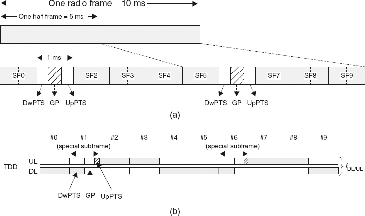
Figure 10.2 Type-2 Frame structure. Reproduced by permission of © 2010 3GPP. Further use is strictly prohibited.
A special subframe consists of three fields: a Downlink Pilot Time Slot (DwPTS), an Uplink pilot time slot (UpPTS), and a Guard period (GP) in between the two (see Figure 10.2(b)). The lengths of the DwPTS and UpPTS are configurable, but are constrained (together with the GP) by a total fixed length of 1 ms, that is, the duration of one subframe. The DwPTS can be considered as an ordinary DL subframe, that is, 1 ms, and can be used for DL transmission. It may also be of a shorter duration, as it can vary from three to twelve OFDM symbols. The main difference between an ordinary DL subframe and the DwPTS is the number of control OFDM symbols. While the DwPTS has two control OFDM symbols; an ordinary DL subframe would have three symbols. This difference is because of the location of the primary synchronization signal (P-SCH), which is located at the third OFDM symbol in the DwPTS. This difference in location enables the UEs to detect the type of duplexing implemented at the cell during network entry.
Table 10.1 The different downlink-uplink frame configurations defined in the standard. Reproduced by permission of © 2010 3GPP. Further use is strictly prohibited

The location of the synchronization signal in FDD is located at the middle of subframe 0 and subframe 5. The GP is reserved for downlink to uplink transition.
The standard defines periodicities for frame switch-points, that is, switching from downlink to uplink and vice versa, that take place at 5 ms and 10 ms intervals. In the case of the 5 ms switch-point periodicity, a special subframe is used in every half, while in the 10 ms case, a special subframe is only used in the first half.
Table 10.1 shows the different downlink-uplink frame configurations defined in the standard. In the table, D and U are respectively downlink and uplink transmissions, while S is a special subframe for a guard time. Note the subframe 1 in all configurations and subframe 6 in configurations 0, 1, 2 and 4 (i.e., those with 5 ms switch-point periodicity). A switch-point consists of a DwPTS, GP and an UpPTS. In configurations with 10 ms switch-point periodicity, the sixth subframe is only a DwPTS. Subframes immediately following the special subframe (i.e., subframe two in all configurations and subframe seven in 5 ms periodicity) are always reserved for the UL transmission.
Resource Block Structure
The standard defines a resource element as the smallest time-frequency resource that can be allocated over the air. A single resource element consists of one subcarrier over one OFDMA symbol. Transmission in LTE is allocated in blocks of resource elements. A scheduler at the eNB allocates resources in Resource Blocks (RBs). Whether in UL or DL, or under FDD or TDD, a RB is 180 kHz accessed over a single time slot, that is, 0.5 ms. Alternatively, an RB can be seen as 12 contiguous subcarriers and either six or seven ODFM symbols, depending on whether the normal or extended cyclic prefix is employed. This setup is shown in Figure 10.3. The OFDMA subcarriers spacing is 15 kHz. Depending on the implemented channel bandwidth, the number of RBs varies between 6 and 100. Specifically, for 1.4, 3, 5, 10, 15 and 20 MHz channel bandwidths, the number of RBSs is respectively 6, 15, 25, 50, 75 and 100.

Figure 10.3 The LTE Frame. Reproduced by permission of © 2010 3GPP. Further use is strictly prohibited.
An UL/DL Transmission Time Interval (TTI) is one subframe in length, that is, 1 ms.