
QoS in LTE-Advanced
Most of the functionalities and specifications related to QoS and radio resource management deployed by LTE are supported by LTE-Advanced to guarantee backward compatibility, which is an essential requirement for the LTE-Advanced standardization. Specifically, QoS performance measures, classification, signaling bandwidth requests and grants are almost similar to LTE. Bandwidth allocation and traffic handling includes some enhancements required to support the new features included in LTE-Advanced to meet or exceed the IMT-Advanced requirements. In this section, we will discuss the major enhancements related to QoS and bandwidth reservation procedures.
Carrier Aggregation
LTE-Advanced provides support for a new feature called Carrier Aggregation, which entails aggregating two or more component carriers that are either contiguous or non-contiguous. The main objective of Carrier Aggregation is to provide larger bandwidth to meet the IMT-Advanced requirements of a spectrum up to 100 MHz.
Carrier Aggregation has an impact on both scheduling and HARQ. For HARQ, it is required in Carrier Aggregation, whether contiguous or non-contiguous, to have one independent HARQ entity per scheduled component carrier. Note that the maximum number of HARQ entities allowed by LTE-Advanced is eight entities for the FDD duplexing. For scheduling, and similar to Release 8, each UE may be simultaneously scheduled over multiple component carriers. However, at most one random access procedure is scheduled per UE in any timeframe. For TDD, it is required that the number of component carriers uplink should be equal to that of the downlink. As in LTE, a single component carrier is still mapped into one transport block.
Coordinated Multipoint Transmission/Reception (CoMP)
CoMP is introduced in LTE-Advanced to mitigate interference and improve the throughput of cell-edge users. CoMP transmission employs dynamic coordination in the scheduling/transmission and/or joint transmission between/from multiple cell sites, while reception employs dynamic coordination in the scheduling and/or joint reception between/at difference cell sites. This enhancement is mainly related to the scheduling function at the eNodeBs participating in CoMP.
- Joint processing, and is of two types. In the first, data to a single UE is simultaneously transmitted from eNodeBs participating in CoMP to improve the quality of the received signal at the UE or to actively and dynamically participate in mitigating interference at other UEs. In the second, transmission is performed by one eNodeB in a subframe, where an eNodeB is dynamically selected in each subframe to mitigate interference and improve signal quality at UE.
- Coordinated Scheduling/Beamforming. Here downlink data is transmitted from only the serving eNodeB, but the decisions of when and how to schedule this UE is coordinated with other eNodeBs participating in CoMP.
Relaying in LTE-Advanced
Relaying is currently being studied as an enhancement of LTE towards LTE-Advanced, that is, at the moment it is not part of the standard. The main objective of introducing relaying in LTE-Advanced is to provide extended LTE coverage at low cost. Standardization for relaying is at its early stages and is expected to be finalized by the end of year 2011.
LTE-Advanced relay defines two types of relays, Type-I and Type-II. Type I corresponds to the non-transparent relay in 802.16j, yet differs by being strictly limited to two hops. Type-II corresponds to the transparent relay. In Type-I, the relay node controls its own cell and serves only the purpose of extending the coverage to UEs beyond the eNodeBs effective coverage. A Type I relay node is hence required to transmit the common reference signal and control information to UEs. In Type-II, the UE is within the eNodeB coverage, and is capable of receiving the eNodeB's common reference signal and control information directly. The main objective of Type-II relay node is to increase the overall system capacity by achieving multipath diversity and transmission gains at the UE.
LTE-Advanced relay accommodates different relay transmission schemes to be implemented at the relay node such as:
Amplify and Forward: The simpler transmission mode, and one that is operated at the physical layer. In this mode, the relay station amplifies the signal received from eNodeB (UE) then forwards it to the UE (eNodeB). Type-II relay can employ this transmission mode. While this mode has the advantage of short delay, both the signal and the noise are amplified in the signal relaying process.
Selective Decode and Forward: A relay station employing this transmission mode is capable of limited MAC layer functionalities, specifically channel decoding and cyclic redundancy check (CRC). A relay station decodes the received signal and checks the received message for errors by checking the correctness of the CRC. If the CRC is correct, the relay station performs channel coding then forward then signal to the UE or eNodeB. The selective decode and forward prevents propagating erroneous messages along the path to the UE. It does, however, incurs longer delays than the amplify and forward due to time required for channel decoding and CRC processing.
Demodulation and Forward: Here, the relay station demodulates the received signal without performing channel decoding or CRC checking. The signal is hence amplified without the noise, and the relay station provides less delay than the selective decode and forward scheme because of the lower processing time. However, it cannot avoid propagating erroneous messages because it does not perform CRC checking.
From the point view of relay architecture LTE-Advanced-relay defines two types of connection between the relay node and eNodeB, namely inband and outband. These connection types are shown in Figure 12.3.
In case of inband connections, the eNodeB-RN link share the same band with direct eNodeB-to-UE. This is applicable for Type II relay. For outband connections, the eNodeB-RN link does not operate in the same band as eNodeB-UE. To enable the inband communications, LTE-Advanced-relay defines resource partitioning procedure with backward compatibility, where network resources are reserved for the eNodeB-RN link and cannot be used by the access link. Figure 12.4 shows the downlink resource partitioning among the relay link and the access link. The resources are time division multiplexed over the same frequency band between the access link and the resource link. A Similar procedure is defined for the uplink communication.
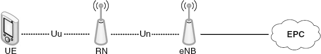
Figure 12.3 LTE-Advanced-relay architecture: redraw to unify the objects used to represent the UE and eNodeB. Reproduced by permission of © 2010 3GPP. Further use is strictly prohibited.

Figure 12.4 Downlink resource partitioning for Inband-connection. Reproduced by permission of © 2010 3GPP. Further use is strictly prohibited.
Scheduling
Scheduling in relay mode is noted in TS-36.912 document to be backward compatible and utilizes the procedures and approaches defined in release 8 (LTE). LTE-Advanced-relay defines new downlink physical control channel called the Relay-Physical Downlink Control Channel (R-PDCCH) and two shared channels the Relay-Physical Uplink Shared Channel (R-PUSCH) and Relay-Physical Downlink Shared Channel (R-PDSCH) respectively. Scheduling procedures over these channels are similar to the procedures discussed in Section 14.1.4.1, where semi-persistent and dynamic scheduling are permissible. Scheduling in relay mode can be divided into centralized and distributed scheduling depending on the type of the control provided in the relayed network.
Centralized Scheduling
The eNodeB is responsible for scheduling all links of the network, relay links and UE links over the one and two hops distance of the network. The relay node only forwards the received data and signaling from the eNodeB without any scheduling. Global information (channel state information) is hence required at the eNodeB about all network links to engage a centralized scheduling algorithm. To meet the latency requirements of IMT-Advanced and to optimally schedule resources in the network the channel state information of the relay-UE node have to be up-to-date using fast transmission on the backhaul links. Centralized scheduling can be employed in both relaying types.
Distributed Scheduling
In LTE-Advanced relaying networks employing distributed scheduling, the scheduler resides at both the eNodeB and the relay node. An eNodeB schedules resources on the eNodeB-RN links and UE directly connected to the eNodeB, and the RN schedule resources on RN-UE links who are two hops distance from the eNodeB. Channel state information of the relay node-UE link need not to be relayed to eNodeB. Consequently, less signaling and overhead is expected in distributed scheduling relay networks. Distributed scheduling can only be employed in Type I relaying networks.
HARQ
Two types of HARQ are defined, end-to-end and hop-by-hop. The end-to-end HARQ is simple because the eNodeB has full information about the status of each HARQ transmitted block. HARQ is performed at the eNodeB and the UE, the relay node only relays data and control message between the eNodeB and the UE. The relay node in this case has no contribution in processing. In the event of retransmission/s, the relay node combines the current message with the previously received messages using the maximal ratio combining then forwards the message. The UE decodes the message and checks for errors using the CRC, and sends back an ACK if the CRC is correct or a NACK if not. The message is forwarded to the eNodeB by the relay node, in case of NACK the eNodeB successively retransmits data corresponding to the same message.
In hop-by-hop HARQ, the relay node not only forwards the data from/to eNodeB/UE, but also contributes in processing. For example, when a relay node receives a message from the eNodeB distant to the UE, the relay node decodes the message, checks the CRC and generates its own feedback (ACK or NACK). When retransmission at the relay node or the UE link occurs, the relay node or the UE, respectively, combines the currently received message with previously received message/s before decoding, decodes the message then forwards the feedback to the eNodeB or relay node respectively. Hop-by-hop HARQ is more efficient than end-to-end HARQ because messages in error are not forwarded and transmission incurs shorter delays. However, decoding and message processing is required by each relay node, which implies that a relay node should support more complex functionality than in the end-to-end HARQ such as buffering and queuing, decoding and CRC checking.