
3.11Banknotes and security printing
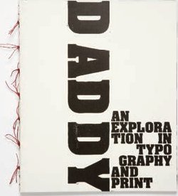
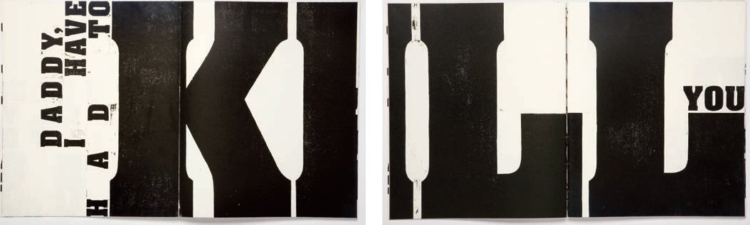
Bjørn Ortmann, a student at Central Saint Martin’s, College of Art and Design, London, adapted the classical approach to woodblock carving by using large sheets of thin plywood to design Daddy, an Exploration in Typography and Print, these pages from the book feature a poem by Sylvia Plath. Like Ilse Buchert Nesbitt, Ortmann worked with a reverse-reading paper guide but one from a digital output. He cut around each of the characters before stripping away the top surface of the veneer to create raised typographic letterforms. The woodblocks were printed page by page in imposition on signatures on an Albion press. Some of the text, such as KILL, bleeds off the fore-edge of the page and continues on the reverse. The lettering was based on typographic forms but, being hand-cut, the letters are not absolutely identical either in form or in the way they are printed. The distressed patina reflects the nature of the poem.
Woodblock printing is a process that dates back to second-century CE China where designs and writing were printed on to textiles and paper. The tradition of printing continued throughout the Far East for over a thousand years before there is evidence it developed in the West. By the seventh century, parts of China had introduced woodblock printed paper money. The earliest surviving printed book is the Diamond Sutra of c.868, Buddhist teachings printed from woodblocks.
The earliest surviving Western so-called block books – such as Biblia Pauperum, Apocalypse and Ars Moriendi – featuring woodblock illustrations and written in the roman alphabet date from c.1460.The technique was most widely used in Germany, France and the Netherlands but its popularity declined rapidly with the introduction of copper and steel engraving, which reproduced finer printed lines and, therefore, smaller letterforms. Although woodblock printing was superseded in terms of speed by letterpress printing, it remained popular until the second half of the nineteenth century. It was associated with fine printing and championed by William Morris (1834–96) and the Arts and Crafts Movement. Morris ensured it was taught in the emerging art schools. Other technical developments were introduced by the Post-Impressionist painter Paul Gauguin (1848–1903) who began carving plains (areas of wood cut to two depths) and inking them with separate colours to produce two-colour images, often black and brown, from a single pull.
The side grain of soft fruit woods, such as pear and apple, as well as hardwoods like poplar, lime and maple, are ideally suited to woodcutting as the long grain is fine and even. The wood must be well seasoned and free of any knots before it is mechanically planed flat to 2.3cm (7⁄8in) or type high (the standardized height of letterpress type).
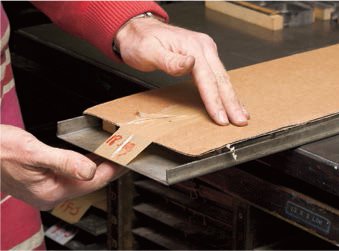
The lettering design must be drawn in reverse on the surface of the woodblock. Because of this requirement few cutters draw letters directly on to the block. One of the finest American cutters, Ilse Buchert Nesbitt (see opposite) is an exception in that she can draw a wrong-reading image directly on to the block. Most calligraphers like to draw right-reading letters on to tracing or typo paper using pencil or ink. The paper is then flipped and glued to the surface of the block and provides an accurate visible outline for the carving. If the lettering is to be printed black, the majority of the surface wood surrounding the letterforms must be cut away. If the lettering is to be reversed out (the black ground is printed, and the lettering is defined by the white unprinted surface of the paper), the cutter must remove the wood inside the letterform. Woodcutting like engraving allows no space for mistakes, as any slip or misplaced mark on the surface of the block affects either the letterform or the ground, and will be reproduced in print.

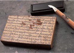
1 Woodblock cutters make use of a range of tools. They tend to use a burin with a V section. After writing the text, with a pen and ink on tracing paper, Ilse Buchert Nesbitt pastes it to the surface of the block wrong-reading and begins to cut away waste wood around the outline of the letters using a paring knife. Note the oilstone for sharpening the knife.
2 Ilse cuts away from the letter outlines towards the waste wood using a double-handed grip; the left hand pushes behind the blade and the right hand resists. This approach offers both power and control at the cutting edge.
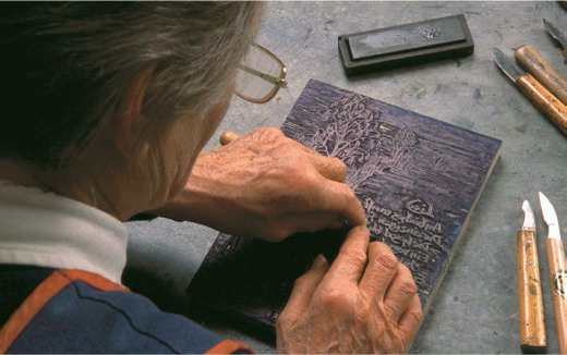
3 The work is slow and painstaking as each letter and connective must be cut around, and the interline and word and character spaces cut away to an even depth, allowing the lettering to stand proud. Outlines of the letters are cut with a slight avit, which means the base of the letter is broader where it meets the newly cut surface of the block than at the letterface. This minimizes the edge of letters being chipped when under pressure during printing.

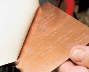
4 As the work progresses, Ilse can make test proofs to review the quality of the cut and refine the letterforms. This detail shows the exquisite quality of the cutting.
Gutenberg’s first press was based on the technology used in winemaking. It differed from all previous presses in that it combined both an up-and-down movement, applying pressure to transfer ink from the type to the paper, and a separate in-and-out motion, positioning the form and paper. This type of press, made almost entirely of wood, is referred to as a joiner’s press. A solid, wooden frame supports a large, wooden screw which, when tightened, exerts pressure on a plate or platen, forcing the paper down on to the inked typeface and creating the impression.
Simple wooden presses offered the printer a good impression and were successfully used for two-colour work that required accurate registration. Letterpress printing enabled a single printer, having set a text, to reproduce multiples and thus industrialize the production of language. Printing in the sixteenth century was often referred to as mechanical writing. Although far quicker than the human hand, the new technology could produce no more than 100 sheets per day. Printing was slow as each impression involved re-inking the press by hand, moving the protective frisket (stencil), positioning a new sheet of paper and pulling and tightening the screw thread. The economic incentive to reduce the time and, therefore, the cost of each pull (while retaining or improving the crispness of the impression) became the printer’s obsession. By 1600, two printers working on a single wooden press at Christopher Plantin’s publishing house in Antwerp, Belgium were capable of printing 1,250 sheets per day on both sides.
Letterpress was to remain the most important method of reproducing text until photo composition was more widely adopted in the 1960s, after which magazines and illustrated books could be reproduced lithographically (see pp.102–05). Letterpress remained the means of producing newspapers until the mid-1980s when digital technology in the form of the Apple Macintosh computer enabled designers to create digital typesetting that could be read straight to a lithographic plate by a process known as Computer To Plate (CTP, see pp.104). The decline in letterpress printing was almost terminal as in the late 1980s thousands of compositors and printers lost their jobs. The rapid change in technology was particularly devastating for many long-standing family-owned letterpress printing firms who simply could not adapt. Their customer base fell away, labour costs were too high and their capital assets – the type and the presses – were deemed obsolete and plummeted in value. As a consequence, they did not have the money to reinvest in new equipment, were unable or disinclined to acquire digital typesetting skills, and could not afford to invest in lithographic presses.
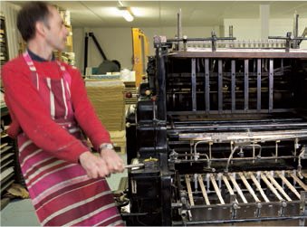
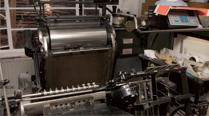
So what is the future for this obsolete process? Letterpress, the iron horse of printing, has in a sense turned full circle. It has returned to its craft roots as a resurgence of interest in small-batch production among younger designers, combined with the experience of older printers and devotees of the historical letterpress, has ensured its survival as a craft in some enlightened art and design schools. There it forms a key element in the teaching of typography. It is also used in private presses that produce limited editions and in small workshops such as Phil Able’s Hand & Eye Press. Able demonstrates printing on a small rotary press (opposite) and on a larger Heidelberg book press (overleaf); the type is composed by Gloucester Typesetting Services on a hot metal Monotype caster.
As well as text, letterpress printing is used to print images, drawings, diagrams, illustrations and simple maps that often include letterforms. This type of printing is called blockwork. The artwork can either be hand-drawn in black ink or, as in this case, designed digitally before being output as a high-resolution black print. The block is made photographically by a specialist block maker, using an acid-etching process.
Block printing
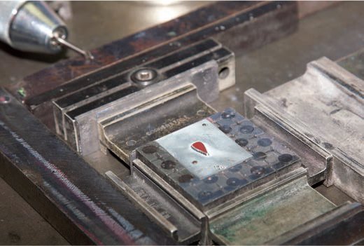
1 Here a second solid colour (blue), is to be spot-printed into a lozenge already printed in black. The plate is attached to a special block, a metal matrix of holes with hardwood cores. Holes are drilled into the plate and tiny panel pins are hammered through the plate into the wooden cores.

2 The proof is pulled and the colour matched against a Pantone swatch book. The registration is checked and minor amendments made to the position of the block on the bed, to avoid the white line and ensure that the trapping (the dark colour overlapping the light one) is clean.

3 The block is positioned on a small, single-colour platen press, and sheets with the previously printed black map are fed into the press by hand. The paper is lifted on to the block and the blue lozenge is printed inside the black outline.
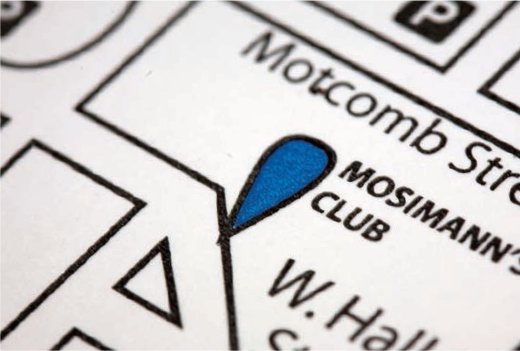
4 A detail of the final print shows the correct colour and clean trapping.

A small single-colour invitation card includes a letterpress-printed block of a drawing.
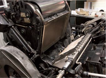
Printing on a Heidelberg book press
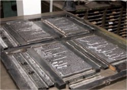
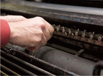
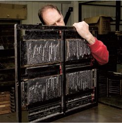
1 A letterpress book is printed several pages at a time on to a large sheet of paper, which is then turned over and printed on the reverse. The sheet is folded into a signature before being stitched into a book and cut down to size using a guillotine. The process of arranging the galleys of type into book pages is called imposition. Here a large book chase is blocked out with furniture and quoins to secure the form.
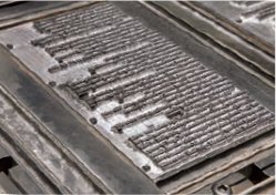
2 The type for the book – the script for King Lear – shown here has been set using hot metal on a Monotype compositor as opposed to cold metal or hand setting. The detail shows the large amount of spacing material used in setting plays: dialogue is set line for line.
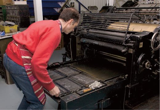
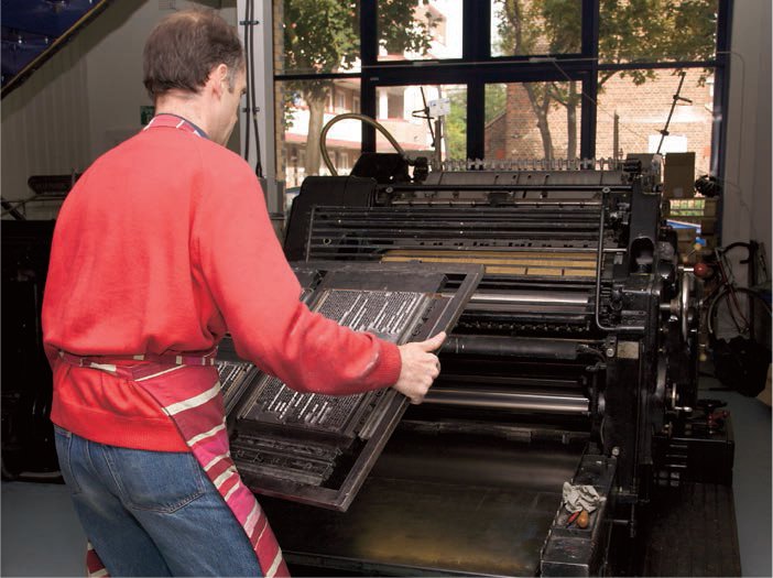
3 Once the form has been locked up, it is lifted from the stone and placed on the bed of the Heidelberg cylinder press. The form is gently lowered into place and positioned square with the cylinder.
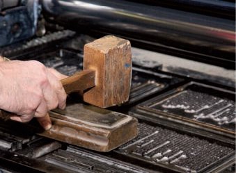
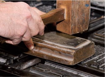
4 The quoins are loosened just a little and the type is tapped down with a small wooden block and a mallet. This ensures that all the type is level, as it can rise slightly in the form during the short lift from stone to press bed.
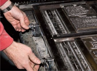
5 Two screws are adjusted to make the form square on the bed.
6 A large press shares some of the principles of the smaller proofing press but allows far finer adjustments to be made. Here the gap between the top roller and the steel cylinder is adjusted by turning little tappits to ensure both parts are parallel and that the space between the two is even.
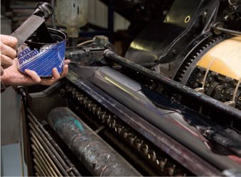
7 The cylinder, like the proofing press is inked with a pallet knife.
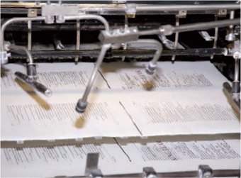
8 The large press has an automatic paper feed. A single sheet of paper is picked up from a stack by little vacuum suckers, and travels around the cylinder, over the type where the impression is made and back to rest above the original paper stack. The pages of the book generally have consistent margins, so the printer positions the printed type in the same place on every page. The baselines of the type on one side of the sheet should match those on the reverse.
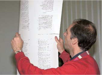
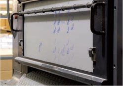
9 To ensure the baselines are consistent, the printer takes a sheet from the previous signature and makes a pull. He then holds the sheet to the light and marks any correction that must be made. The type form can be moved marginally forwards or backwards until the baselines match.

10 The printer now looks at the quality of the impression: evenness, consistency of inking and crispness of type. The whole type form on a cylinder press is not in contact with the paper through the entirety of the impression. The paper is progressively forced down on to the type as it is drawn around the cylinder and progressively released. Although the process is very quick there is what printers refer to as a dwell (a pause when type and paper are in contact). As the cylinder passes over the type, the release of pressure on the form may cause it to lift slightly, a characteristic referred to by printers as spring – an undesirable effect that can slur the type. Here the printer marks up uneven areas of type.

11 Crispness of impression on a cylinder press relies on the paper being evenly forced down on to the type. The distance between cylinder and type must be consistent throughout the rotation. If the type is slightly proud, the impression will be bold; if the gap is too great, the impression will be weak. The steel cylinder is surrounded by packing (sheets of paper that cushion the impact and prevent the type being crushed). The sheets are held in place by a blanket or tympan (an oiled sheet of Manila card). The blanket can be removed and the packing behind it increased or reduced.

12 By taking a printed sheet from a previous signature and placing it under an impression from the new form, the printer can mark with a scalpel where pressure needs to be increased or reduced – a process referred to as make ready. Holes that can be cut into the packing sheets for pages or individual lines to reduce pressure or sections can be pasted over one another to increase pressure. This adjustment process may take up to two hours before the final print run can be made. The press is run at 2,000 sheets per hour.

The Heidelberg book press is robust yet allows for very fine adjustments. In the hands of a master printer the quality of impression is crisp, even and clean.
The locked up pages, referred to as a ‘form’, are secured in a book chase. This chase is made up of four rectangles, one for each page. The chase must have minimal flex as all of the type characters, lead spacing units and furniture are secured only by the pressure applied between the quoins and the chase.
When all the fine adjustments to the impression are complete, the press can be rolled and printing begins.
Storing forms and distributing the type
1 Once the sheet has been printed the form is removed from the press bed and returned to the stone and unlocked. The press is then cleaned.
2 Any loose type that has lifted during the move from the press to the stone is tapped down and the form is unlocked.
3 Individual pages are separated, tied up as a smaller form using a thin binding string and stored on a galley (a thin, three-sided metal tray on which the type is laid and tightened). Furniture blocks out the side of the galley and a sheet of card is taped over the form.

4 The galley is slid carefully into a galley frame for storage. Only when a book is printed and bound are these forms broken up and dismantled.

5 The process of returning hand-set type to the individual boxes within the case is called distribution. Machine-cast metal type such as Monotype, Linotype and Ludlow setting and casting is usually returned to the compositor in a galley to be smelted down. All the type must be returned to the correct box within the right case. This is checked by selecting a wide cap, such as ‘H’, from the galley and removing the same cap from what is thought to be the correct case and comparing them. If the case is the right one, the type is lifted from the galley, held in the left hand and returned to the correct box with the right hand. Damaged type is smelted down and cast into new type.
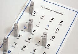
Special characters and scripts used for setting non-Latin languages such as Hebrew are cast on metal body sizes which match with the Latin alphabet enabling languages to be combined.
The versatility of letterpress printing is demonstrated by the range of work that makes use of the process.
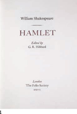
1 A title page from Hamlet published by the Folio Society, set by the Monotype metal caster (see pp.60–63) and printed on the Heidelberg press by Phil Able at Hand & Eye Press.
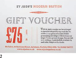
2 A letterpress gift voucher printed two-colour for St. Jude’s Modern British features a range of decorative metal fonts and a lozenge combined with a wood-type £75.
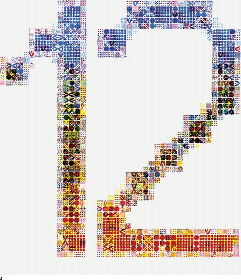
3 Michele Jannuzzi produced a series of letterpress numerals for a calendar. The large number 12 is made up of decorative border elements and overprinted in several colours.

4 A design by Martin Z. Schröder laid out on the imposition stone.
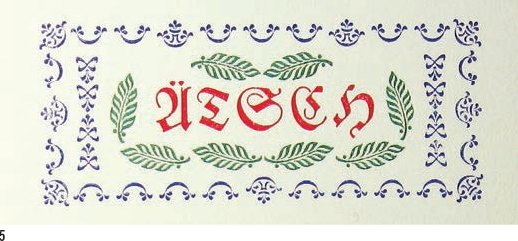
5 Schröder used similar decorative border elements, associated with nineteenth-century design, in the production of this three-colour card.
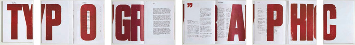
1 Front and back cover and a series of spreads from TypoGraphic no. 60, designed by A2-GRAPHICS/SW/HK. The large, wooden letters printed by Stan Lane of Gloucester Typesetting Services (see Hot metal casting pp.60–63) spell out the title throughout the publication.
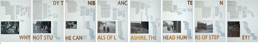
2 A series of pages from ‘In Darkest England’, a boxed set of loose sheets primarily printed by letterpress, designed by David Jury and reproduced at Foxash Press. The type visualizes memories of the same event. Different opinions are linked in progressively smaller type sizes and narrower columns as they move further from the original text.
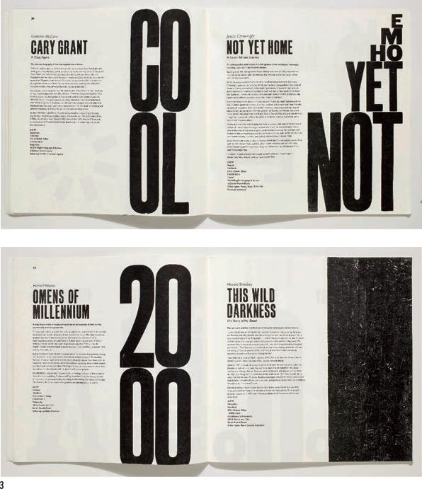
3 Frost Design produced this catalogue for the publishing group Fourth Estate. It is printed entirely by letterpress and makes extensive use of woodblock and metal letterpress characters.
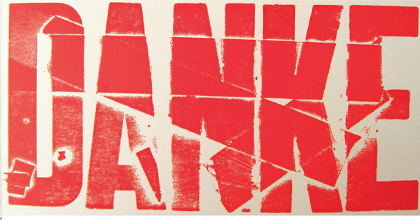
4 Martin Z Schröder’s DANKE makes use of the expressive qualities of letterpress printing.
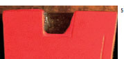
5 A detail of the woodblock ‘A’ which shows the ink spread across the surface responsible for the patina of the print shown above.
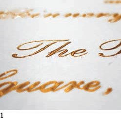
Thermography is a print process often used in combination with lithography and letterpress printing. Powder or crystals are sprinkled over wet ink, and, when placed under a heater, the lettering rises above the surface of the page. It is sometimes referred to as imitation engraving and has been widely used for printed stationery, letterheads, envelopes, business cards, invitations, Braille and, occasionally, in publishing. Some letterpress printers in the early twentieth century experimented with crystals ground from hardened tree sap, which expanded when in contact with the wet letterpress ink. Today’s process, developed in the 1970s, uses thermographic powder ground from a plastic resin. The thermographic crystals produce a range of different finishes – gloss, semi-gloss and matt – and metallic powders produce a metallic sheen which is less expensive than foil blocking (see pp.66–67). Glitter can be added to make a kitsch, sparkling effect. Pearlescent resins separate the ink pigment to produce a soft, pastel, rainbow finish and high-viscosity powders thicken the ink, preventing infill and preserving fine lines, serifs and counters in small type. Laser-safe powders have been developed to allow thermographic type and logos on letterheads to pass through photocopiers and laser printers without the raised surface being destroyed by re-exposure of the sheet to a heat source. This form of thermography uses ultraviolet-sensitive inks which are sealed, like tin plate printing (see pp.117–119), with ultraviolet exposure units. All the finish variables are available with different particle sizes: extra fine particles are used for type under 14pt, fine for type between 14pt and 30pt, medium for sizes up to 48pt and coarse for all sizes above 48pt. Thermography is sometimes used to create the relief dots in Braille as an alternative to embossing. This is particularly useful when print for sighted readers has to be combined with Braille, as the thermographic dots can be printed in a clear yet raised varnish.
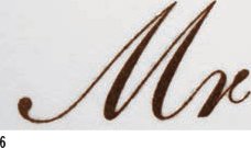
Examples of thermographic printing, the lettering is lifted above the surface of the printed card.
1 The rounded forms of the thermographic printing are visible when the printed surface is viewed from an oblique angle.
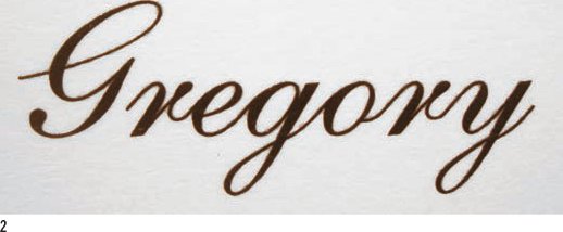
2 Large script type must be evenly sprinkled with powder so that all the thin connectives are lifted above the sheet.
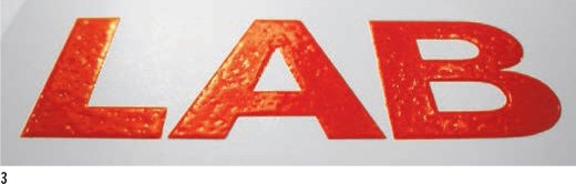
3 The patina made by the reaction between the ink and the thermographic crystals is clearly illustrated when coloured letters with a large surface area are viewed from an angle.

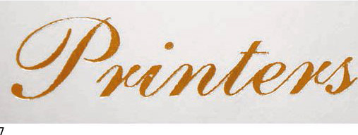
4 and 7 A gold, metallic ink is thermographically raised above the sheet (4), but is slightly less crisp than the foil blocking debossed through a gold metallic foil (7).

5 A detail of 6pt type shows how the counter forms hold up if the finest crystals are used.
6 A detailed enlargement of 8pt type.
Raising the type above the surface of the page

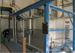
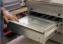
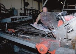
1 Thermography occurs immediately after the sheet of paper has been printed, while the ink is still wet. It can be done by hand process, sprinkling the crystals over the ink, removing the excess and drying the lettering under a heater. However, at Postglow and Frankel Printers, London the process is far more sophisticated. The printing and thermography are combined into a single production process referred to as in-line thermography.
2 Sheets from a stack of paper are fed one at a time into the press, which has a small bed that prints sheets up to A3 – and is typically used to print stationery.

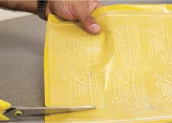
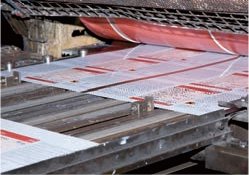
3 Sheets move through the press and the impression is made. They exit the press print-side up and are moved along a sealed conveyor belt into a chamber (not shown), where the themographic crystals or powder are dispersed by a mechanical shaker. The crystals cover the whole sheet, both printed and non-printed areas, but stick only to the ink. The sheet continues down the conveyor belt and passes under a vacuum which sucks up all the loose crystals.

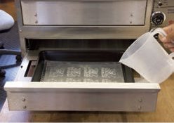
4 The sheet now passes through an electrically heated oven. Here the heating unit has been lifted above the sheet-conveyor belt to show the glowing elements. While the machine is operating this unit, like the crystals’ chamber, is closed. The oven reaches temperatures of between 480°–670°C (896°–1238°F) depending on the type of powder or crystals. The resins in the crystals melt and combine with the pigments in the ink to form a congealed solid, which is slightly domed in profile. This part of the process is referred to as curing.

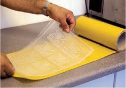
5 The sheet exits the press face-up. The type is hard and can be stacked and knocked up (the sheets are made square and parallel) without interleafing (the insertion of blank sheets to prevent the accidental transfer of ink from the face of one sheet to the reverse of another).

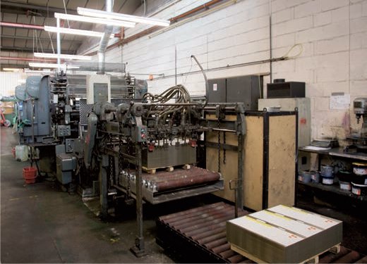
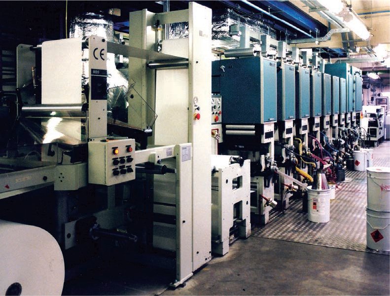
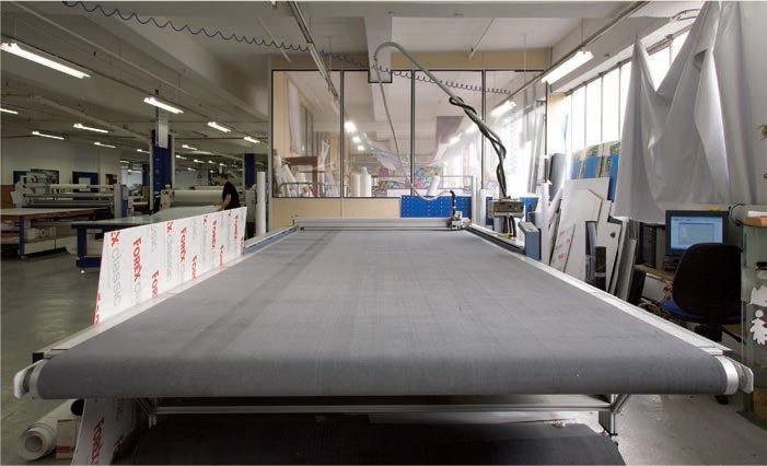
Two massive litho presses arranged in parallel on the print room floor. Each press features ten ink pyramids, which, when run in line, can print up to ten colours at a single pass.
Offset lithographic printing is the most common form of printing used to produce books today. The term lithography is derived from the Greek lithos, meaning stone, and graphein, to write: writing on stone. The process was invented by the Bavarian dramatist Aloys Senefelder (1771–1834) in 1798. Lithography transfers ink directly from the surface of the stone or plate to the surface of the paper. It is based on the simple principle that grease and water do not mix. Thin aluminium or zinc plates with a finely-grained surface are prepared: a fine film of water is applied to the entire plate, then a greasy substance is applied to the image areas of the plate and the water is retained on the non-print surface. Ink adheres to the greasy image areas, but is rejected by the wet, non-print areas. The inked image is transferred to the surface of the paper while the clean, damp areas of the plate leave no mark.
Photography was invented in the late 1830s; by 1851 experiments had culminated in a light-sensitive lithographic stone from which a photographic image could be reproduced. As photography developed, it became possible to separate a full-colour image into three process colours (cyan, magenta and yellow) and a fourth tone (black). Using these four process colours (known as CMYK), full-colour reproductions of half-tone images were possible. Lithography, which made use of colour separation, registration and multiple-roller cylinder presses, had become a sophisticated commercial print process.
By the beginning of the twentieth century, offset lithography, in which the ink is transferred, or offset, from the printing plate to a rubber-covered cylinder before being printed on paper, could lay down more colours more quickly than letterpress machines and was ideally suited to the reproduction of images. Its drawback lay in its reproduction of type. Lithography was principally a way of reproducing drawn and photographic images. Calligraphic lettering and engraving were reproduced lithographically throughout the nineteenth century, but books, being text-led, were not commonly reproduced using offset lithography until the 1960s, when the uptake of photo-typesetting enabled type to be transferred to a lithographic plate through a photographic negative.
Offset lithographic presses are either sheet-feed (one sheet at a time) or web-feed (a continuous roll of paper). Large sheet-feed presses can run at 12,000 sheets per hour but their capacity is dwarfed by web-feed presses, which are capable of 50,000 sheets per hour. To ensure high quality, books tend to be run at slower press speeds than newspapers, cheap brochures, or packaging, where high volumes of more than 100,000 per run are required.
Lithographic presses are typically either single-colour, two-colour, four-colour or six-colour, although specialist presses have been built to deliver more selected colours at a single run. Single- and two-colour presses may be used for four-colour printing, with the sheet passing through the press in registration several times.

A poster designed by Studio Dumbar. This example shows some of the refinements made possible with lithographic overprinting.
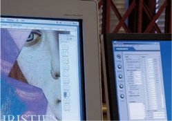
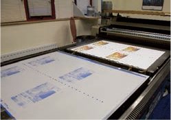
1 Today virtually all artwork for lithographic reproduction is prepared digitally on screen. Software such as Quark Xpress and InDesign enable the designer to specify all the colours within a digital artwork. Some smaller presses have retained photographic processes for making the colour separation films for each of the plates.

2 Lithographic plates, thin sheets of aluminium, plastic – or for the cheapest short-run jobs paper – coated with a light-sensitive substance. The substance varies depending on the plate manufacturer, examples are a diazo compound or a photopolmyer. Plates must be thin and flexible as they have to be wrapped around the cylinder of the press. The texture of a lithographic plate is slightly granular, which traps moisture on its surface. Here the plate (blue sheet) is placed in a tray before being slid into Computer To Plate (CTP).

3 The Computer To Plate (CTP) machine uses a laser to guide and write or expose the type, and half-tone imagery in the form of a dot screen, on to the plate guided by the digital postscript file. Each separation – cyan, magenta yellow and black (CMYK) – must be exposed on a separate plate. Special, additional selected colours or varnishes also require individual plates. Here the plate has been laser-written and is being removed from the CTP machine.

4 The exposed plate is manually moved into a Kodak processing or developing unit. Some CTP machines laser-write and develop as an uninterrupted, automated process.

5 The plate exits the processing unit. Where the laser has exposed the plate, the image and lettering are retained while the unexposed areas are washed away. The type and imagery on the plate is wrong-reading.
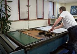
6 Once all the plates have been written and processed, a short run of the job is printed on a proofing press and a proof is pulled. The proofing process provides a traditional wet proof, using ink. This enables the designer and client to view the colour on the paper stock that will be used for the final job. Plates on the proofing press are laid flat on the bed. Here they are being secured.
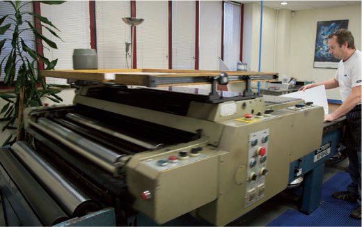
7 Printing wet proofs requires press time and a printer to set up the press and oversee a short run. It is therefore slower and more expensive than producing dry proofs. Here the ink rollers and paper carriage have moved over the plate of the proofing press before the sheet is removed.
8 The plate (left) and the CMYK paper proof (right) rest on the bed of the proofing press. Cheaper dry proof techniques have been developed. Some use photographic processes and other dyes. Not all require a press, yet enable the designer to check layout and registration, and give a good, though not exact, indication of colour.
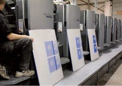
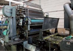
1 This large incline press has eight ink pyramids – towers of rollers that move the ink down on to the lithographic plate before it is transferred on to the cylinder roller and finally on to the paper. Here three plates lean against their appropriate ink pyramids before the pressman attaches them to their plate cylinders.

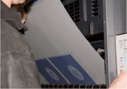
2 The flexible aluminium plate is wrapped around the plate cylinder (top) and secured. The rubber blanket cylinder (below) is used to offset the image and text wrong-reading from the plate and print it on to the paper right-reading. An impression cylinder (not visible) beneath the blanket cylinder provides sufficient pressure to transfer the image evenly on to the paper.
3 Before ink is applied the lithographic plate must be moistened so that the non-image areas reject the ink. A very fine film of water is rolled over the surface of the rotating plate cylinder. It is delivered to the plate via a series of rubber rollers linked to the dampening fountain (a reservoir of water and alcohol). Here the damper fountain is checked.

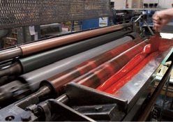
4 Yellow ink from the can has been scooped into the ink reservoir with a palette knife. All lithographic presses are made up of many rollers which move the ink from the reservoir at the top of the press down the ink pyramid to the plate cylinder. The order in which the four colours are applied can be varied depending on what the designer wants the overprinting to look like. The lightest colour yellow is usually printed first followed by magenta, cyan, black and, where required, an ultraviolet (UV) seal or varnish.
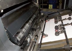
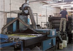
5 Presses are either sheet-feed like this one, or web-feed like newspaper presses. In the latter the paper is printed as a continuous strip. Individual sheets are picked up by tiny pneumatic vacuum suckers that lift them from the hopper into the press. The paper is then moved through the press to the first ink pyramid (yellow) by a series of rollers and air beds which form a continuous conveyor belt.
6 The pressman can monitor all the ink pyramids, and the pressure between the individual blanket cylinders and plate cylinders remotely from a screen that also regulates the speed of the press.
7 Ink flows down from the reservoir through a series of rollers to the plate cylinder and adheres to the exposed surface of the image but not to the ground. Text and image are transferred to the blanket cylinder as a very thin layer. The sheet of paper passes between the blanket cylinder and the impression cylinder. Ink is transferred from the blanket cylinder to the paper. The sheet is then moved to the next ink pyramid. The sheet passes through all four colour pyramids and the UV seal.
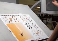
8 Every so often sheets are removed from the run and taken to the inspection table where they are checked for registration, the alignment of the colours, dot gain (the quality of the half-tone and ink density). The ink density is measured using a densitometer, a hand-held electrical instrument. Fine adjustments to the press can be made instantaneously on the touch screen. Finally sheets are passed through an electrical drier.

Sheets are stacked on a pallet and mechanically knocked-up, the pile is made square. Lithography is capable of producing high-quality reproduction in high volume. Here brochures await boxing up before despatch to the client.

A vandalproof external sign designed for the post office is screen-printed on the reverse of the flexible plastic before being hot-moulded into a blister.
Screen printing evolved from stencil-printing (an ancient process in which ink is forced through a mask to create an image). The Romans, Chinese and Japanese made use of stencils to make patterns on tiles, ceilings and cloth more than 1,500 years ago. The Japanese used a matrix of human hair, but this was gradually replaced by a mesh of silk threads. The stencil was laid over the mesh and coloured ink was dabbed through it to create a pattern. Stencil printing continued in this form until the early nineteenth century, when it was realized that the stencil could be attached to a fabric screen, thereby making it more durable. Silk-screen stencilling then replaced silk-stencil matrixes.
A first patent for silk-screening in 1907 specified that the process involved a mesh screen and a squeegee (a length of wood housing a rubber blade) for pulling the ink and driving it through the mesh. In screen printing some areas of the mesh are masked to prevent the ink passing through them. The image on the screen is right-reading, like the printed image. Screen printing allows flat, opaque or transparent coloured inks to be laid over one another. The amount of ink laid on the paper is far greater than with other print processes and the saturation and vibrancy of the colour give screen-printed images greater appeal. Colour separations can be made and half-tone photographic screens can be reproduced.
Vinyl-cutting artwork for screen printing

1 Vinyl-cut letters are used for internal and external signage (see pp.124–25) and to make large-scale artworks for screen-printing. The vinyl is generally cut by a cutting plotter (a knife attached to a plotting machine). The lettering design is converted in a vector-based program, usually Coral Draw for a personal computer and Illustrator or Freehand for a Mac.
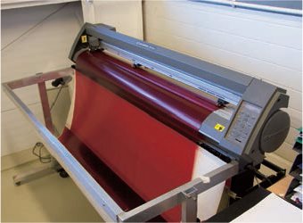
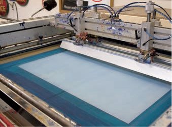
2 The plotter consists of a cylinder that holds a roll of vinyls, here Rubylith the red opaque film used for screen-print artwork – and a cutting blade mounted on an arm. The depth of cut can be adjusted so that the vinyl is cut but not its backing paper. The cutter moves quickly and precisely over the vinyl surface.
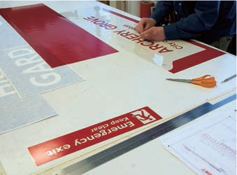
3 When the lettering has been cut, the film must be weeded out. Either the lettering or the background must be stripped away so that the lettering can be used to prepare a screen for screen printing.

The author tests the flexibility of the vandalproof, screen-printed sign. It makes use of polymer inks, which expand and contract, but do not crack or become detached when the plastic sheet of the blister is squashed.
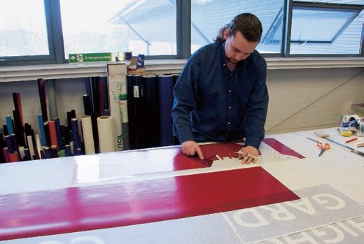
The background for a large panel is stripped away to reveal the positive letters that will form the same size artwork for the screen printing.
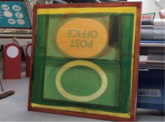
1 The screen consists of a stout, square, warp-free wooden frame with synthetic threads that are stretched absolutely flat. The space between the threads is referred to as mesh grade; the number of threads per 2.5cm (1in) in the weave is referred to as ‘mesh count’. If the mesh grade is fine and the mesh count high, the detail will be retained and subtle half-tones can be reproduced. The four common mesh grades are ‘S’ (the smallest), ‘M’, ‘T’ and ‘HD’ (the thickest).

2 The screen must be very clean and free of grease before it is exposed to the photographic image. This is achieved by washing it in a degreasing agent and checking that the mesh of the screen is completely free of ink particles.

3 In a photographic darkroom, both sides of the screen are coated with a light-sensitive colloidal solution (not shown), a water-suspended emulsion made of polyvinyl alcohol (PVA) or polyvinyl acetate (PVAC). This is often combined with a blue or purple dye that makes the chemical change that takes place during exposure. The screen is then air-dried in a warm room.
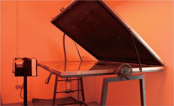
4 The screen is moved, under a safe light, to the photographic exposure unit. Black or coloured type is produced from a positive artwork, a process referred to as printing on (lettering is black or Rubylith red); reversed out lettering is produced from a negative artwork (the ground is dark and the lettering white). The screen is contact-exposed so the lettering artwork or film is ‘ss’ (same size as the final print). The film is laid emulsion-side up on the glass, the screen is lowered print-side down on to the film, and a vacuum pump is turned on to suck the screen and film together so that they are flat on the glass bed. Ultraviolet light is turned on and the exposure made.

5 The exposed screen is lifted to the wash-out unit where it is wetted on both sides and then sprayed, from the printing side, with lukewarm water. The areas of the screen exposed to the ultraviolet light harden, while those masked by the film are washed away. The screen is then dried prior to printing.

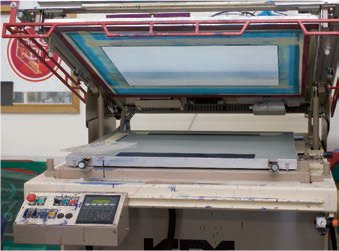
1 The screen-printing press consists of a metal frame, about waist high, across which a melamine-faced wooden bed is secured. Its smooth surface is drilled with a matrix of tiny holes through which air is drawn by a vacuum pump. This fixes the paper on which the image is to be printed in position. The screen is locked above the bed in a hinged frame.
2 The screen is lowered over the bed. The ‘sheet fall’ (position of the paper on the bed in relation to the screen) is marked and the frame is lifted again. Printers temporarily stick either masking tape or small, cardboard L-shaped guides to the bed, which locate the corners of the paper and ensure all sheets are positioned in the same place.
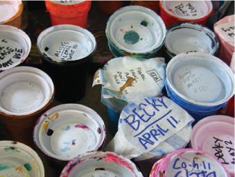
3 The appropriate ink has to be matched to the correct surface and required visual finish. Screen printing is used to print opaque colours (by adding an extender base), fluorescents, metallics, pastels and varnishes (by adding tinters), solid or half-tones in gloss, silk or matt finishes, and even scratch-and-sniff inks. Water-based inks can be used to print on paper and card, while oil- and acrylic-based inks are generally used for non-absorbent surfaces such as metal and glass.
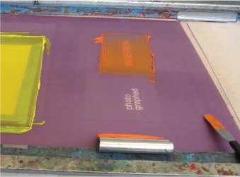
4 Ink is poured on to the reverse of the screen at the front edge, forming a viscous pool. A squeegee at least 3.75cm (1½in) wider at either end than the lettering is used to charge or ‘flood’ the stencil. The frame is lifted slightly above the paper and the squeegee is used to push some of the ink away from the pool or reservoir over the stencil and towards the hinge. A thin layer of ink is absorbed into the mesh of the stencil, which is now charged.
5 The printer places the squeegee behind the reservoir of ink at an angle of 45 degrees, before slowly and smoothly pulling it towards himself or herself at a consistent speed, retaining a firm and even pressure. The pull is continued beyond the edge of the stencil so that the ink is well clear of the stencil. Pressure applied by the squeegee to the reverse of the screen forces the ink in the stencil out through the mesh and onto the surface of the paper. A crisp print relies on a clean screen, a clearly defined stencil, well-mixed ink of the appropriate viscosity and a consistent pull.
6 Once the pull is completed, the screen is raised a little and the squeegee is used to pull the ink away from the stencil. It is then rested against the edge of the frame where it holds back the ink reservoir. The screen is raised a little further, which automatically cuts out the vacuum and allows the printer to lift the sheet from the bed to the drying rack.
A batch of posters is stacked in the drying rack overnight.
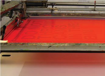
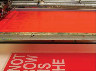
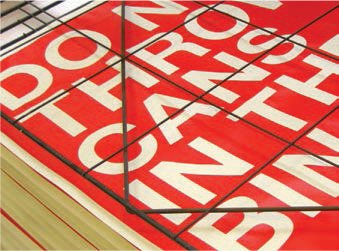
A series of screen-printed posters promoting recycling, designed and printed by Becky Redman.
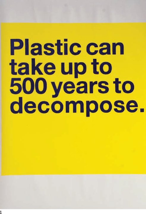
1 Black type printed over a solid yellow ground.

2 Right- and wrong-reading letters printed in two colours in register and deliberately aligned to imply recycling.
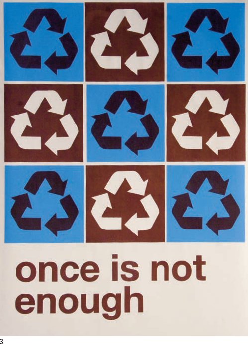
3 Repeated recycling symbols printed brown over blue and white reversed out of brown.

4 A full-bleed pink ground overprinted in black.
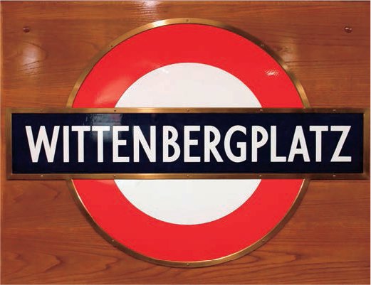
A German enamel metro station sign.

Full-size model of a London Underground platform at A. J. Wells. The illumination levels can be varied to test how signs will show up in an emergency.
Enamel is best defined by the French word from which it is derived: esmaile – literally glass on metal. Vitreous enamel is formed by melting glass and bonding it to a metal surface to give an exceptionally hard surface which is resistant to everyday wear and tear and requires a deliberate act of vandalism to be scratched or chipped. It has the additional properties of excellent colour saturation, luminosity, resistance to ultraviolet light, and colour retention; it is waterproof, frostproof and easily wiped clean. Throughout the late-nineteenth century these hard-wearing properties were exploited to make metal baths, tin plates, industrial lampshades and cooker hobs. The qualities of vitreous enamel also make it ideal for internal and external signage in dirty, urban environments.
Enamel signs were used in advertising from the 1910s until the late 1950s, when large-format printed billboards proved cheaper. During the 1970s and 1980s many rail networks and metro systems worldwide began to adopt cheaper vinyl signage, which adhered directly on to walls, or powder-coated platform signs. However, vinyl signs proved less durable than the older enamel versions, were subject to vandalism and, exposed to harsh exterior conditions, they faded and peeled, while the powder-coating became dull and chipped. Many European rail and metro networks have begun to review their platforms signs and enamel signs are beginning to reappear.
A. J.Wells based on the Isle of Wight, England is a long-standing enamelling firm that produces enamel-coated wood-burning stoves and baths. It has developed a signage division which is now responsible for nearly 90 per cent of Transport for London’s signage. The factory manufactures signs from both sheet metal and enamel, on one site without subcontracting or outsourcing. London Underground is the oldest metro system in the world and was not designed on standard units but was developed line by line by individual companies. Many of the panels, fascia boards, platform signs and even the Underground roundels vary between stations and must therefore be custom-made.
A range of enamel car badges with cast metal lettering.
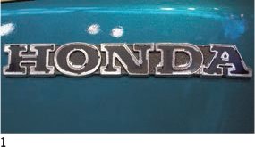
1 The slab serif, bold expanded lettering of this cast, zinc Honda logo has been infilled with black.
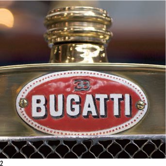
2 The much older Bugatti badge is a three-colour surface enamelled on a brass plate.
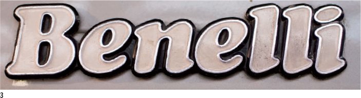
3 The Benelli metal casting is outlined in black, infilled in old white and the keyline is polished back to the metal.
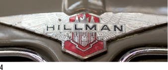
4 The polished wings of this Hillman badge show how the very fine details of the casting can be infilled with a colour that is sitting flush to surface.
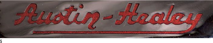
5 The lettering of this Austin-Healey mark is infilled with a transparent enamel.

6 A complex italic casting with a simple infill.

7 The casting of these numbers, like the ‘Benelli’, is infilled with a colour that lies below the surface to allow the keyline to be polished.

8 The famous Jaguar mark featured enamel casting at the centre of its wheel hubs.
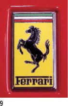
9 The five-colour infill of the Ferrari badge featuring the prancing horse.
10 The two-colour green and yellow lotus badge; note how the yellow has been matched to the Daytona yellow of the car’s paint.

11 The simple Bentley ‘B’ is surrounded by a relief decorative casting of a pair of wings created through an engraving process.

12 The metal Cobra lettering is picked out by a red enamel infill.
1 Before enamelling can begin, the metal must be thoroughly degreased. Because of the number of signs in production this process has been automated. The signs and sheets to be enamelled are loaded into racks in the degreaser which resembles a 5-m (16-ft 5-in) high dishwasher. The metal is cleaned with detergents and from this point on must be moved with gloves – even finger grease will affect the enamel bonding to the metal surface.

2 The enamel must be made into a paint. This is done by grinding the tiny glass balls into a powder and adding water to form a thick paint. Colour is added to the mix in the form of frits (very thin, biscuit-like fragments of glass in different colours). The mixing process takes between four and six hours, and the enamel paint is stored in plastic bins.
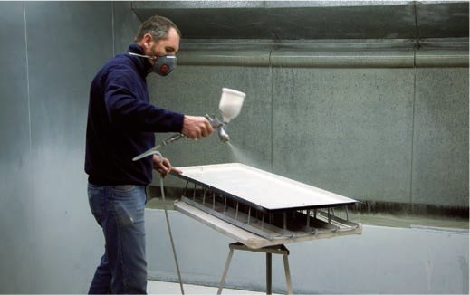
3 The signs must be base-coated with enamel paint. This is applied in a spray booth with an airbrush. By suspending the signs on painters’ S-hooks, both sides can be sprayed prior to drying. The sign is carried to the electrically heated drying cabinet where all the water evaporates from the painted surface in an ambient temperature of 90°C (194°F). The enamel paint is now in a fragile biscuit-like form which can chip easily. The sign is carefully moved to the furnace.
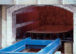
4 The sign is fired in the furnace for approximately eight minutes at a temperature of 800°C (1,472°F). It is here that the tiny glass particles melt across the surface, and fuse with one another and into the metal to form a cohesive sheet. The glass is no longer on top of the metal but becomes part of its surface.
5 The base enamel is allowed to air-cool on pin racks.

6 The screens are made either photographically on film or by a computer-controlled cutting plotter. Artwork for each job is stored until the job is complete. Here lettering cut on a plotter (see p.106) is weeded out by hand.
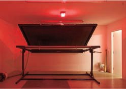
7 The huge exposure table is designed to accommodate the largest sheet size (2 x 3m/ (9ft 10in x 6ft 8in) used on the screen-printing bed and on the London Underground panels. This ensures the lettering can, where necessary, run edge-to-edge across the panel.
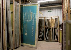
8 The exposed screens are washed and dried before being job numbered and stored in huge racks.

9 The lettering and lines for the London Underground track diagram shown on this screen must be printed in several colours but the artwork has been produced on a single screen as each coloured element can be masked. Only in cases where the enamel is over-printed must separate screens be made (see pp.106–09).

10 The sign is positioned on the screen bed, the screen lowered over it and coloured enamel paint is poured onto the reverse.

11 A squeegee is pulled across the enamel paint, forcing it on to the sign. Several colours can be applied at the same time, providing they do not butt up or overlap. The sign is removed to the drying room where the water evaporates. A mistake at this point can be scratched off the surface before firing.

12 The process of screen-printing, drying and firing goes on until all colours have been fired. Here a large track diagram is removed from the furnace. Repeat firing may affect colours already laid down. As there are 12 colours on the London Underground diagram, different batches of enamel are mixed which match two-colour firing with six-colour firing. The printers carefully record the order of firing on each sign.
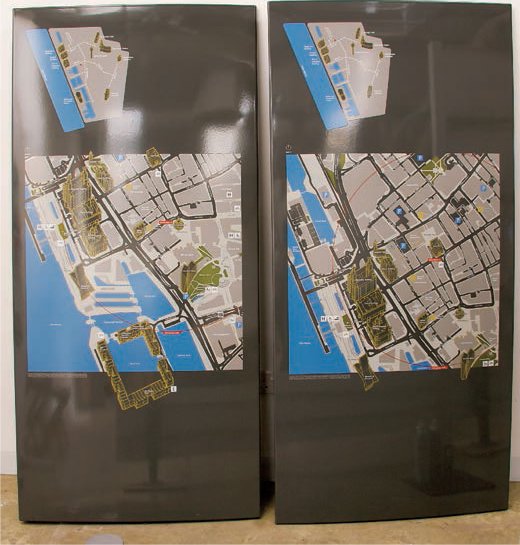
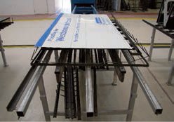
Front and back panels of a freestanding sign from an environmental signage system developed to guide pedestrians around the city of Liverpool.

A detail from the map shows how the enamel process has been pushed to its limit to produce a very well-designed piece of public information. The signage system is superbly crafted, with some of the maps featuring up to 12 colours.
Rubber stamps have been used since the mid 1860s and have a wide range of applications. The term rubber stamp is often limited to small hand-held stamps associated with passports, postal franking, commercial certification and administrative approval. However, this apparently simple technology is used for a wide range of relief printing purposes which are not possible with lithography (see pp.102–05) and gravure printing (see p.120). The technique supports printing on to many different materials, such as plastic, polythene bags, wood (for example, fruit crates) and food products (such as eggs).
Today companies like Polydiam have developed and refined many different methods of rubber stamp manufacture, suited to the production of small-scale document stamps or large-format printing purposes. Making stamps from vulcanized rubber is the oldest process and continues to be popular, particularly when a large batch of the same stamp has to be reproduced. Naresh Kapadia of Polydiam has produced over 30,000 official stamps at a time, for electoral ratification at polling stations. The company builds many different sizes of machine but they all work on the same principles. Vulcanized stamps are hot-press moulded into a form.
Vulcanized rubber stamps
1 A wrong-reading relief plate is made from an artwork; the lettering stands proud of the surface. The plate can be made of etched magnesium or zinc (see 168–69), laser-etched metal (see p.155), it can be engraved (see p.157) or, as here, it can be made from a plastic polymer. The plate is then placed face-up in a small tray.

2 The tray is lifted into the top of the cabinet and covered by a flat sheet of matrix board. The electric heater at the top of the unit is turned on and softens the matrix board.

3 The handle is pulled down and an impression is made through a combination of heat and pressure.
4 The matrix board has a right-reading impression debossed below the board surface. The plate (bottom) and the matrix board (top) are separated.

5 The matrix board cools quickly and is placed face-up on the tray with a sheet of rubber over the surface.

6 The tray is returned to the unit where heat and pressure are again applied. Heat makes the rubber sheet pliable, while the downward pressure forces the rubber into the letter cavities in the matrix board.
7 Left to right: polymer plate, matrix board and a vulcanized rubber sheet ready to be cut down and glued to a stamp block and handle.
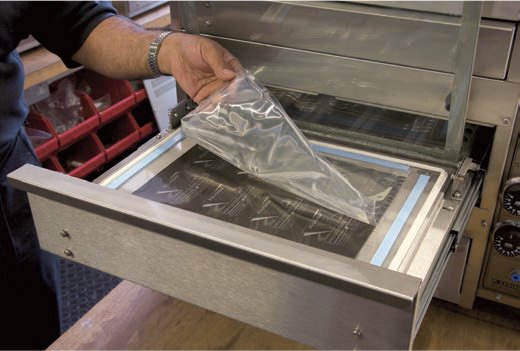
1 Photo polymer stamps are made from a light-sensitive plastic polymer. The stainless-steel production cabinet is self-contained, each of the four production phases being isolated in a drawer. A photographic negative of the artwork is placed on the glass sheet that forms the bottom of a drawer in the exposure unit. The polymer, which can be used for making stamps, or moulds, or plates for traditional rubber stamps, is in liquid form and sealed in a plastic bag. The polymer bag is laid flat on the negative.
2 A glass lid is closed over the bag and a vacuum pump is turned on. This sucks air out from between the two glass sheets and flattens the liquid polymer (trapped in its bag) into a flat sheet of even thickness.

3 The drawer on the exposure unit is now closed and the liquid polymer sheet is exposed to two ultraviolet light sources to harden it. The top light falling directly on the polymer hardens it to form what will become the backing sheet, while the bottom light passes through the type and image areas of the photographic negative. The water-soluble polymer only hardens in areas where it is exposed to ultraviolet light.
4 The exposure unit is opened and the now stiff polymer sheet is removed. The plastic bag is cut away. The sheet is placed in the washing tray at the top of the unit and cleaned with water. The soft, unexposed polymer is washed away leaving the hard, wrong-reading type standing in relief above the surface.
5 The final curing process, ‘post exposure’, must take place in an environment where oxygen is not present as a gas. The sheet is placed face-up in the bottom drawer of the cabinet and covered in water. It must be completely immersed before being exposed again to ultraviolet light for a further ten minutes. The curing process makes the sheet very durable.
6 The clear polymer sheet is detacked using a powder, then laid out on a crack-back adhesive.
7 The stamp design is glued to the stamp block.

The finished stamp and printed image.
Hot foil blocking is used in stationery, card packaging, cigarette boxes, on moulded PVC packaging and for labelling on leather products – stamping the maker’s name on the sole or inside lining of a shoe. It can even be used on wood, for example, on presentation boxes for wine. As the foil is metallic, a true reflective or mirror finish, which cannot be matched by ink, can be achieved. Hot foil printing is ideally suited to type where the letterforms may be small but are printed at 100 per cent; it is not well suited to half-tone reproduction. Automated hot foiling machines, capable of printing an entire book cover with a relatively large block, are used to produce raised metallic type on best-selling paperback books and can run up to 8,000 prints per hour. Smaller hand-operated machines used for stationery can run at up to 200 prints per hour. The foils come in a wide range of metallic finishes, colours, patterns and holograms (see p.64) but are not produced in Pantone colours. Postglow and Frankel Printers specialize in hot foil blocking for stationery.
Applying hot foil
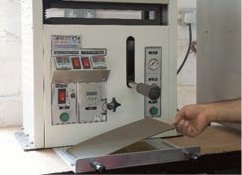
1 A platen press with a heated plate is used for hot foil printing.
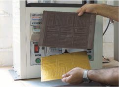
2 The metallic foil is made from several layers: a carrier film, a release layer, a varnish, a pigment layer and, finally, an adhesive layer. All the layers except the carrier film (the white sheet) and the release layer, are transferred to a sheet of paper. The foil can be produced as a roll or, as in this case, sheet form and in a range of metallic finishes.
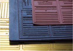
3 The block or die was traditionally hand-engraved (see pp.158–59) in copper or brass but today is made of magnesium or zinc – often referred to as a Zinco. It is produced by a diemaker from a black and white artwork. For debossed lettering, the die will be wrong-reading and printed from the front. For embossed lettering it will be printed from the reverse of the sheet and the die will be right-reading. The best embossed lettering is produced with male and female dies.
4 For debossed work the die is secured against the heated plate, the paper is slipped into the grippers and the foil is placed adhesive side to the sheet in front of the paper. The plate is electrically heated to 97°C (206°F) and then the press is closed. The platen presses down on the sheet for a slightly longer dwell time (the duration of the impression) than most presses and bonds the foil into the debossed lettering.
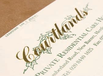
5 This finished stationery sheet combines surface-printed green lettering with foil-blocked script.
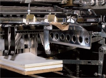
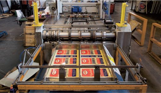
There are two principal forms of tin or aluminium can: one is the folded can made from preprinted sheets fabricated into a three-dimensional form with either crimped or welded seams, and the other is the aluminium, drawn and wall-ironed (referred to as DWI) can. The DWI process was invented in the United States in 1966, and the cans are printed after manufacture in their cylindrical form. The sizing, printing, lacquering and hot-oven drying process is identical to the one for sheet manufacture. Peter Luff Tin Printing and Box Decoration is a family firm that uses the same processes for printing on both tin and aluminium sheets.
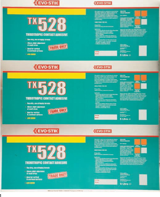
1 Tin plate printing traditionally makes use of special rather than CMYK process colours. Here a 76 x 102-cm (30 x 40-in) sheet, from which glue tins will be made, is printed three up in four colours: white, yellow, green and red.
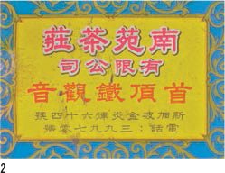
2–4 Decorated tin plate tea tins.
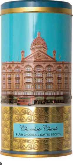
5 A decorative biscuit tin, printed as a flat sheet bent around a form and either pinch folded or automatically soldered, makes use of CMYK, and special plate blue (not a tint), mid-blue, black and is overprinted in gold and then debossed.

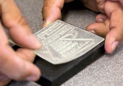
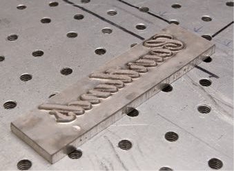
6 The lettering design for a whisky cap lies flat on the plate; note that the baseline of the signature is curved.
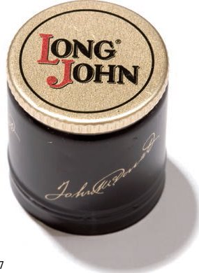
7 Once the whisky cap is pressed into shape, the signature appears to run around the cap.
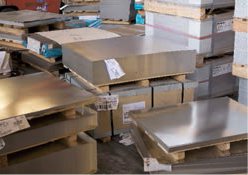
1 Both tin and aluminium plate are produced in many different gauges, but boxes and cans are manufactured from 0.22mm to 0.8mm (approx. 1⁄72in to approx. 1⁄32in) sheets. Far thicker sheets can be printed but are difficult to fabricate. Here precut tin and aluminium sheets await the sizing process.
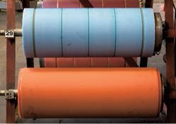
2 The areas of the sheet to be printed must be presized, but those which form the joints in fabrication must remain raw metal to enable ‘clean’, folded lock joints or welded seams. Rubber rollers with a groove aligned with the box joint are made for each size of tin.
3 To allow the ink to adhere to the surface the metal sheet must be sized with either acrylic or a polymer. The size must be printed evenly across the surface.

4 Once the sheets have been sized, they are stacked face-up and drawn off the stack onto the press by pneumatic suction pads.
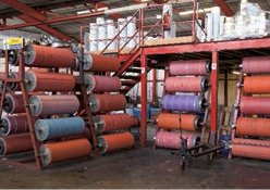
5 The lettering artwork for tin plate printing is prepared in exactly the same way as for lithography or gravure. Tin plate printing can be in either CMYK or selected special colours. Each colour is printed by a rubber roller located at the bottom of the press and supplied with ink from a reservoir suspended on a gantry above the press bed. Ink is moved to the blanket cylinder via a chain of rubber rollers referred to as an ink pyramid. The rollers revolve against one another ensuring an even distribution of ink. Inks for tin plate printing must be solvent-based in order to adhere to the size.
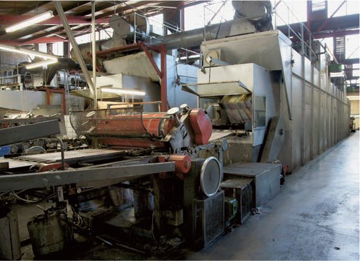
6 The tin plate passes quickly under an ultraviolet light unit suspended across the press, which immediately dries the ink before the second colour is applied. This instant drying enables solid colours to be butted or overlaid in successive workings as opposed to organizing a printing order based on areas that do not touch.
7 The plate is moved on to the second roller where an identical ink pyramid delivers a second colour. The plate continues under another ultraviolet light which instantly dries the ink.

8 Plates are dropped into a stack. This two-colour press can be run at up to 4,500 sheets per hour. Newer four-colour tin plate printing presses may run at 6,000 sheets per hour. This is slower than sheet-fed litho presses or roll-fed presses as the laid ink must have sufficient exposure to ultraviolet light to dry off.

9 The press is periodically stopped and the registration and ink lay, and the crispness of the dot screen for half-tones, are checked periodically under a daylight bulb.
10 The plate passes through the press and the ink is printed on to the sized tin sheet.
11 When all the colours have passed through the press and been laid they must be sealed with a varnish or lacquer. Like the size, this can have an acrylic or polymer base. The sheets are picked up off the stack.
12 The varnish must only be laid over the printed surface of the tin, leaving the seam allowance raw for the seam weld. An identical rubber roller to the one used in the sizing process (with matching grooves) is used to lay the varnish.
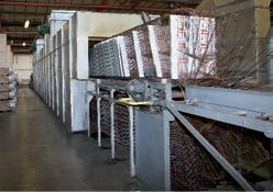
13 The sheets are lifted on a racking conveyor belt into a gas oven and heated at a temperature of 170°C (338°F). Each sheet passes through the oven for 15 minutes.
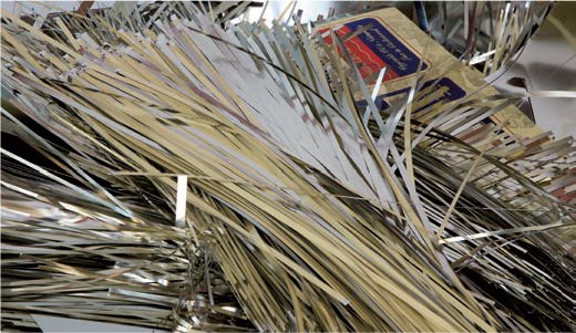
Tin plate printing is an environmentally friendly process as both the tins and the offcuts shown here can be recycled.
Printed sheets are guillotined down to size so that the tins can be folded and pinched into shape.

A heavy-gauge metal drum with very crisply printed white lettering over a red ground.
Gravure printing is predominantly used in the security printing industry to reproduce stamps and, in some countries, banknotes.
The incline, roll-fed press resembles a large, modern lithographic unit. The reel of paper (bottom left) is pulled through a succession of ink pyramids. Here six pyramids with different coloured inks are aligned. The seventh pyramid carries an ultraviolet varnish seal. The slightly taller cabinet at the far end of the press is a UV drying unit. Stamps can be printed on crack-back or glue strip (traditional lick-the-back) in a single pass.
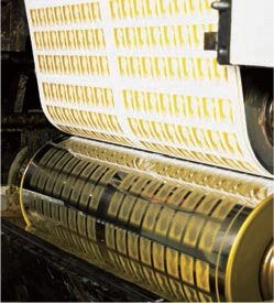
The revolving gravure plate (bottom) clearly shows the identical laser-engraved rows of stamps. With each revolution of the roller the engraved surface is reinked. The paper is pressed on to the cylindrical engraving plate from behind by the impression cylinder and the ink is drawn out of the half-tone indentations in the plate and onto the surface of the paper. It is then UV-sealed and dried in a single operation. The stamps are perforated after drying.
Intaglio print processes including etching, engraving and gravure hold the ink in grooves below the surface of the plate. The gravure process is also known as rotogravure, which refers to the cylinders around which the plate is wrapped in a fashion similar to the system used in the offset lithographic press. Gravure has twin qualities of continuous tone and consistency of ink lay throughout a run, which make it suitable for extremely high-quality printing, such as art photography, banknotes, postage stamps, coupons and security printing, and for cheaper mass-volume products such as catalogues, glossy magazines, wrapping and wallpaper.
The artwork for gravure printing, like that for the offset lithographic process, is likely to be digital and is made in exactly the same way for either print process. The CMYK colours are separated to produce four plates. The separations are converted into plates by a digital signal that controls a diamond-tipped engraver, which cuts into a copper plate. This process can also be realized using laser-engraving, again driven from a digital colour separation. Making a gravure plate is significantly more expensive than making an offset lithographic plate, and is specified by publishers for books with very long print runs of several million copies or because of the very soft tones or exceptionally fine lines that can be printed using the process. The high cost has led to a decline in the number of printers working with the process. Attempts have been made to close the financial gap between the two processes by making photo-polymer gravure plates that use stainless steel and are as cheap as lithographic plates to produce.
The image is printed by drawing out the ink that sits below the surface of the plate. Half-tone images are broken down into a series of tiny dots. The larger or deeper the dot, the greater the volume of ink carried in that area of the plate. Large, deep dots give good ink coverage with almost no visible screen, while tiny dots create very subtle tones – a feature treasured by designers.
3.11 Banknotes and security printing

Front (right) and back (far right) of a 200-franc Swiss banknote. The complexity and sophistication of the design devised to prevent forgery also contributes to the unique, beautiful visual language associated with banknotes. The face and the seated figure reading a paper (top of note) have endless subtle variations in line and colour. The tone that defines the image is created by combinations of multiple colour overlays rather than a single black plate.
Security printing is a generic term used for all forms of printing in which the sheet of paper represents value, for example, banknotes, postage stamps, tokens, cheque books and lottery tickets. The history of banknotes has seen official printers attempting to stay one step ahead of the forger. Most banknotes today are printed with combinations of photographic and hand-engraved plates using both lithography and gravure printing processes. Some countries use letterpress to mark the individual banknotes with a specific number, while many make use of 12-colour printing, foil strips within the paper, complex watermarks, embossing, tinted varnish and holographic printed elements. Most modern notes have at least 24 security ‘elements’ designed to prevent forgery.
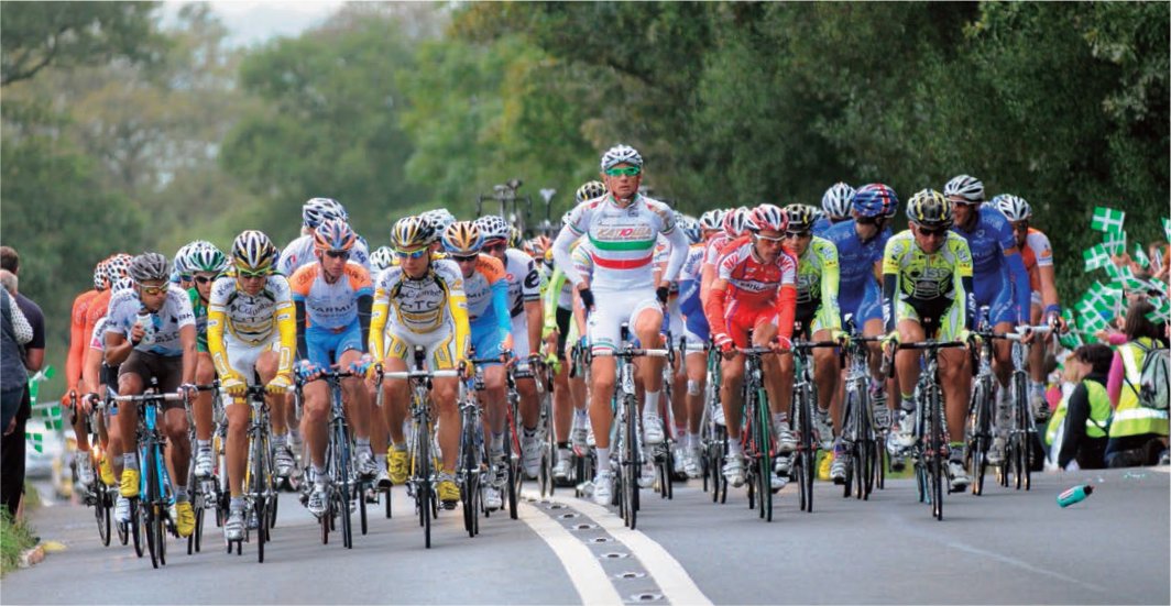
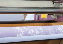
Dye-sublimation printing produces vibrant colours and is ideal for printing stretch fabrics and banners and flags, as well as for sports clothing and garment labelling. Here advertising slogans and brand names emblazon the shirts and colours of professional cycling teams.
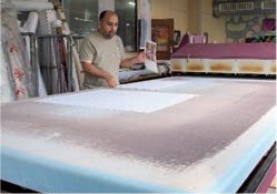
Dye-sublimation, a term often shortened to dye-sub printing, supports full-colour CMYK printing on a wide range of substrates – polyester fabrics, synthetic canvases, sportswear, carpet tiles, rugs, ceramics and many materials that have been precoated with a 60 per cent polyester compound. First developed in the late 1950s, dye-sublimation has grown in popularity since the mid-1990s – due to the increased sophistication and speeds of large-format inkjet printers – as a means of reproducing lettering, photography and artwork. An inkjet printer is used to print dye and not ink on to paper or a plate from where heat and pressure transfer it to the surface of the fabric. Sublimation is a scientific term used to describe the process in which a substance changes its state from a solid to a gas without becoming a liquid. The dye on the paper sheet is subjected to intense heat and becomes a gas, while retaining the pigment colours. The gas is trapped, cools quickly and reverts to a solid dye again. It solidifies into rather than on to the surface of the polyester, which itself has been softened by heat. The pigment particles penetrate the fabric, cool and form a bond in the surface of the polyester. This fusion of fabric and pigment make the lettering or image very durable – the fabric can be folded, crumpled, washed and even pressed without fading or peeling. The colours are vibrant and true to the printed original. Unfortunately dye-sublimation cannot be used with natural fabrics like wool, cotton or linen as it relies on ones that soften with intense heat, enabling the dye to penetrate. Nor can dye-sublimation be effectively used on dark fabrics as the dye does not sit on the surface but penetrates it.
The dye-sublimation process is used in two ways: CMYK combined transfer in which all the CMYK colours are bonded simultaneously in a single heating and pressing; and CMYK plate or special (selected colour) transfer in which each dye colour is heated and printed separately. For the latter, the plates must be accurately registered on the fabric. An additional lamination finish, which protects the fabric against subsequent high temperatures, ultraviolet light and to some extent scuffing, can be printed to seal the fabric. Opposite, Dhafer Moosa at Stylo Graphics shows how a digital image is prepared for dye-sublimation printing.

1 The image is printed wrong-reading on an inkjet printer. However, instead of ink the cartridges contain dye suspended in a liquid carrier. The CMYK colours are used. On some printers greys are created with a separate cartridge rather than from the CMYK mix. The image on the paper looks very similar to a conventional inkjet image.
2 The flat bed shown here, is 3 x 1.5m (9ft 10in x 4ft 11in). Resolutions up to 600dpi can be printed. As the text on the fabric will expand when hot and contract marginally when cooled the sizing must accommodate a 1–3 per cent change. The digital image must be flipped so that the text is wrong-reading.

3 The paper is laid text- or imageup on a polyester fabric. A second strip of fabric is laid over the paper image. The heat is then set to 200°C (392°F). When the electrically heated metal platen reaches the correct temperature it can be lowered on to the bed.

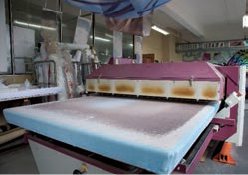
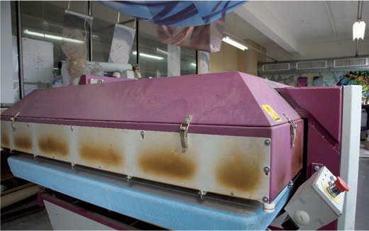
4–6 The pressure must be adjusted according to the type and thickness of the polyester. Large pneumatic rams force the hot platen down onto the fabric which is allowed to ‘cook’ for a minute. The platen is moved progressively down the length of the bed.
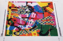
7 The platen is lifted and the backing fabric is removed to reveal the vibrant, right-reading print. The paper is left with a very pale image and the carrier as most of the dye has been transferred and fused to the polyester.
8 A roll printer rather than a platen dye-sublimation printer is used to print a roll of fabric 1.8m (5ft 11in) wide and over 30m (98ft 5in) long. A heated roller initiates the sublimation.
Detail of a dye-sublimation print for Stella Artois lager reproduced on a heavily textured waterproofed fabric.
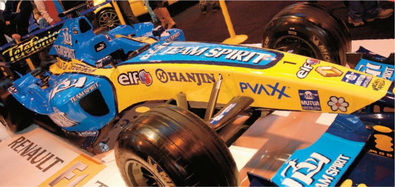
The moulded shell of this Renault F1 racing car is adorned with the printed and knife-cut vinyl lettering of its sponsors.
Vinyl is the shortened name for a plastic polymer, polyvinyl chloride (PVC), but may also be called ethenyl. It is produced in self-adhesive sheet or roll form and is a relatively cheap and extremely versatile medium for lettering. Self-adhesive letters can be cut from a huge range of colours and effects – metallics and pastels, clear and opaque, holographic patterns, high-visibility fluorescent and reflective – and in finishes such as non-reflective matt, silk or high gloss. Some vinyls can be printed single- or double-sided with CMYK or inkjet, lithography or overprinted with screen printing. Vinyl lettering can be cut wrong-reading or right-reading and comes in a wide range of weights for interior and exterior use. Vinyl is also waterproof and can be resistant to ultraviolet light. It adheres to nearly all surfaces that have a smooth, clean face. The low cost, and speed of production and application, together with the versatility of vinyl, has led to its wide-scale adoption, from signage and branding to exhibition design and packaging. It has been available to graphic production houses since the early 1980s and has completely changed the way many environmental lettering jobs are undertaken.
For the graphic designer, vinyl-cutting offers exactness of detailing: lettering can be positioned line-for-line, kerned at the required scale on screen and reproduced identically. For a retail chain the ability to reproduce identical large-format graphics for its stores reinforces corporate identity and gives visual form to the values associated with the brand. Vinyl lettering can be removed from the face of many materials without damaging the surface and new graphics can be applied directly on site without dismantling architectural elements. This facility makes vinyl an ideal medium for seasonal or short-term promotional messages and it is used throughout high-street retail stores. However, the qualities that make vinyl quick to remove also make it vulnerable to vandalism as it can be easily peeled from a surface, though the problem can sometimes be resolved by putting the vinyl lettering on the reverse of glass so that the exposed edge of the type cannot be damaged.
Many exterior-grade vinyls are today guaranteed for ten years against exposure to rain, frost and ultraviolet light. Printed vinyls are generally expected to last for seven years if exposed to ultraviolet light. Despite the large-scale adoption of vinyl by large sectors of the design industry, many graphic designers, typographers, architectural historians, architects, lettering artists, craftspeople, signwriters and, increasingly the public have begun to question the all-pervading intrusiveness of flat, plastic graphic corporate lettering in the architectural environment.

1 Digital design files are checked in a central digital studio, and assigned job numbers relating to the machines on which they are to be reproduced. Files may have to be converted into personal computer platform programs such as Coral Draw, which support some drafting and cutting machines. The lettering must be turned into outline to create a guide path for the cutter.
2 This multipurpose machine is referred to as a graphic ‘router’ as it offers large-format CAM drafting, able to hold pens of different widths. A vinyl cutter (a jaw) can be fitted with a blade and a foamex router (a bit) can be fitted in a rotating chuck. The routing facility is not designed for metal but allows the operator to oversee the cutting of complex shapes in foamex or soft plastic sheets up to 4mm (approx. 3⁄16in) thick. These are often used in retail display and exhibition graphics. The machine bed is 2.5m (8ft 3in) wide and 5m (16ft 5in) long, but lettering that occupies double this length can be cut in a single operation as the bed consists of a rotating blanket. Enough vinyl for the side of an articulated lorry or a container can be cut in single operation. For smaller vans and trucks vinyl graphics for front, back, both sides and even the roof can be cut from a single sheet.

3 A rolling flat bed is straddled by a movable bridge, along which runs the facility carriage, holding the chuck, bit, pen and cutter blade. Some vinyl lettering requires very complex decorative elements or tiny counters to be cut out from a direct-to-media (see pp.128–30) or inkjet print (see pp.126–28). A tiny camera on the carriage is directed at the vinyl laid on the bed. The vinyl surface can be preprinted with special location marks which the camera recognizes, and the cutting blade is relocated accordingly. This intelligent, self-correcting facility compensates for any stretching or contraction of the sheet.
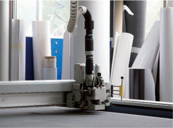
4 The machine operator calls up the appropriate file from the central server and creates a cutting path that links the outline of the successive letters or makes a path around a printed shape. The path includes lift and drop commands that automatically apply the blade in the correct location. The operator can limit the speed at which the blade is run depending on the thickness of the vinyl.
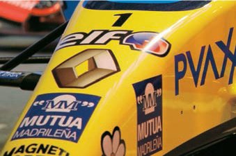
A detail of the Renault’s nose cone shows the printed advertising insignia. The car is painted yellow and blue. All the other colours are added as coloured vinyl, for example ‘PVAX’ on the right of the image; or they are printed on white vinyl, as in the case of the elf logo.
Inkjet printers were invented around 1976 but only really took off in the early 1980s with the increasing use of the personal computer. The manufacturer Canon claims to have been the first to develop the technology with its bubble-jet printer. As with so many technological advances, the invention was accidental. It is said that a clumsy researcher touched an ink-filled syringe with a soldering iron and the instant rise in temperature caused the ink to shoot out of the needle.
Photographic printers producing high-quality hand prints remain but the inkjet printer has become the staple for the presentation of large-format paper dummies used by design companies, advertisers and architects. Exhibition designers use inkjet prints for one-off displays as they can be surface-mounted on panels. Production houses, such as Stylo Graphics who specialize in large-format printing, use inkjet technology in dye-sublimation printing (see pp.122–23) and direct-to-media printing (see pp.129–30). Inkjet printers can be used with solvent-based inks to print on to vinyl (see pp.124–25), used for banners and the plastic tarpaulins on open-sided lorries.
Inkjet printing does not make use of plates, the ink is squirted from tiny nozzles slightly above the paper or substrate. A print head is mounted on a carriage which runs laterally across a track over the paper. The carriage is driven to and fro by small electric motors. On today’s printers ink is delivered in both forward and return movements, thus reducing the print time. The roll of paper is advanced between each pass so that a new strip of ink is printed. Modern printers print groups of pixels four, six, eight, or even 12 deep with each pass. Large-format printers use 300dpi, 600dpi or enhanced resolution 1,440dpi by 720dpi. A large-format inkjet printer reproducing a landscape A1 sheet arranged across the roll puts down at least 224,688 dots per pass in approximately three seconds when printing eight pixels deep at 600dpi.
There are two slightly different technologies among the major manufacturers. Canon and Hewlett-Packard use thermotechnology, while Epson has developed a Piezo crystal system which is fired by variations in electrical current. Both systems produce ink in what is referred to as drop on demand (DOD) where small drops of ink are squirted on to the paper 5,000 times per second.
Thermotechnology has three key stages: heating, bubble bursting and vacuum refilling. A micro resistor, in contact with the ink in a tiny firing chamber above the nozzle, is electrically heated. The ink expands to create a bubble until the pressure of expansion causes it to burst and squirt the ink out onto the paper. The resistor cools rapidly, and the bubble contracts, creating a vacuum, which in turn draws fresh ink into the firing chamber from the cartridge reservoir. Print heads have up to 600 nozzles, each the diameter of a human hair (approximately 70 microns). Each DOD nozzle emits ten pico litres (a millionth of a litre) per squirt, producing a dot between 50 and 60 microns in diameter. The human eye is only capable of seeing a 30-micron dot in isolation and so reads the dots as a solid colour. Colours are mixed by combining cyan, magenta and yellow dots into different groups. Black has a slightly bigger pigment molecule and a larger dot used to create tone.
Piezo crystal technology is a non-thermal process, which does not continually heat and cool the ink in the firing cavity. Piezo was an Italian chemist who realized that certain crystals expand when an electrical current is passed through them. The degree of expansion can be varied by minute adjustments to the strength of the current, creating smaller ink dots and, therefore, higher resolution (up to 720dpi) than that currently produced by thermal technology. The Piezo crystal technology can make use of solvent inks that are drawn into the paper and dry in clean, round dots, creating a very crisp image.
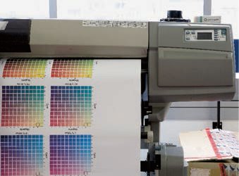
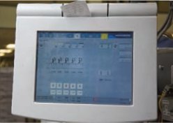
1 Inkjet printers must be regularly cleaned and checked for colour consistency. This is particularly important where finished prints are produced over a number of days and will be exhibited in close proximity to one another. To ensure colour consistency many repro houses, like Stylo Graphics, run out standard digital tint charts daily and check them by eye against those created at the beginning of a client’s run.
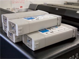
2 Large-format inkjet printers use outsize cartridges. As well as the CMYK colours some printers have additional grey tone cartridges which produce cleaner mid-tones. Other printers can be set up for black-and-white solids, or black-and-white continuous tone, where four cartridge slots use a black and three variations of grey tone in combination to improve the continuous tone in a black-and-white photographic print.
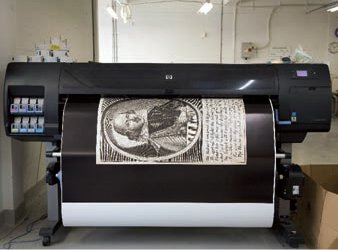
3 A large-format inkjet printer outputs a sheet featuring a portrait of Shakespeare and calligraphic lettering for an exhibition panel. The roll feeder enables this Hewlett-Packard printer to output a continuous paper strip of text or image up to 30m (98ft 5in) in length and 1.40m (4ft 6in) wide at a resolution of 600dpi.

4 A detail of the output, here on gloss paper, shows the depth and solidity of a black printed as part of a CMYK set. The image is printed within three minutes.

5 A panel from the same exhibition features white type reversed out of a solid black. Here it is important that both blacks are identical in quality.

A large-format inkjet-printed advert printed on polyvinyl mesh is stretched across the facade of a building; floodlighting makes it appear to glow above a dark city street. Inkjet printing of this type enables advertising agencies to make use of temporary sites that offers unusual formats. The advertisements have to be customized in terms of scale and crop, and are printed as one-offs.
PVC banner printing
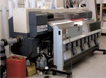
1 Inkjet printers using solvent-based inks are used to produce large-format PVC banners. There are many grades of PVC with different thicknesses suitable for external use. The printer has an additional, electrically heated element positioned immediately in front of the printed roll.

2 As the printed lettering descends it is immediately dried. The solvent must evaporate from the front of the PVC which, being waterproof, is non-porous and will not absorb any of the ink.

3 A detail of the CMYK registration stripe shows the texture of the PVC banner. The printer is capable of edge-to-edge printing but this would mean that the registration and colour bands are run on the short edge. Running them down the roll ensures the operator can continually check the print quality on a long banner, although they must be cut away before the banners is displayed.
Direct-to-media printing, sometimes referred to as DTM printing, is a remarkable form of short-run specialist printing which has, over the last ten years, revolutionized the reproduction of large-format typography, photography and illustration. It supports CMYK, white solids, tints, continuous half-tone and varnishes. Direct-to-media printing can be used on a wide range of materials from paper, canvas, plastics, perspex, PVC, Formica, vinyl, wood and metal to ceramic tiles and even glass. It is referred to as direct printing because it uses inkjet technology to spray the image on to the substrates rather than a plate which transfers the lettering. However, unlike a conventional inkjet printer, the space between the bed and the jet can be varied to accommodate materials up to 4cm (1½in) thick. Special, ultraviolet-sensitive solvent inks are required which, when exposed to ultraviolet light, harden on the surface of the material. The process is ideally suited to the production of large-scale posters, hoardings, and architectural and exhibition panels. Since the adoption of digital printing technologies in the late 1980s there has been an amalgamation of many formerly separate graphic reproduction professions. Large graphic service companies have combined typesetting, digital outputs in laser- and inkjet-printing, artwork, scanning, large-format photocopying, photographic reproduction, platemaking, proofing, rub-downs and screen printing.

A large-format direct-to-media printer represents the latest technology in print production; it enables full-colour lettering and images to be reproduced on virtually any material.
Printing on different substrates
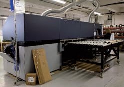
1 The RHO 800 Direct printer resembles an enormous desktop inkjet printer but is approximately 7m (23ft) long.

2 In a large production house the management and processing of individual jobs must be highly organized to ensure the most efficient use of machine time and turnaround. Each job has a numbered paper docket that relates to the artwork stored on the central server. The operator calls up the artwork from the server and identifies the substrate from the docket.
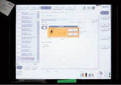
3 The machine is set up for printing by controlling the position of the artwork on the substrate and defining the depth of the material. This direct printer is able to print materials up to 4cm (1½in) deep. Once the material depth has been specified, the machine automatically lifts the ink delivery nozzle a further 1.5mm (approx. 1⁄16in).

4 The ink cartridges for the machine are CMYK plus grey, white and a varnish. It is not possible at present to print varnish with a colour tint, or metallic or fluorescent inks as these would not react appropriately to ultraviolet light. The inks are solvent-based and are pumped to the nozzle head.
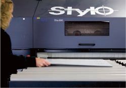
5 A large 1.5-mm (approx. 1⁄16-in) thick plastic sheet is placed on the rollers. The maximum width on this machine is 2.5m (8ft 2½in) edge-to-edge. Printing sheets and panels beyond 5m (16ft 5in) is difficult and they are more likely to be printed as sections. The machine can be adapted for roll-printing materials such as plastic sheeting, PVC or canvas, which can be any length.

6 As the sheet is fed into the printer the carriage head is lowered to the appropriate position, 1.5mm (approx. 1⁄16in) above the print surface.
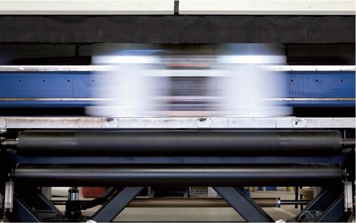
7 The casing of a smaller direct-to-media printer lifted up to show how the inkjet carriage shifts to and fro over the work, printing in both directions.
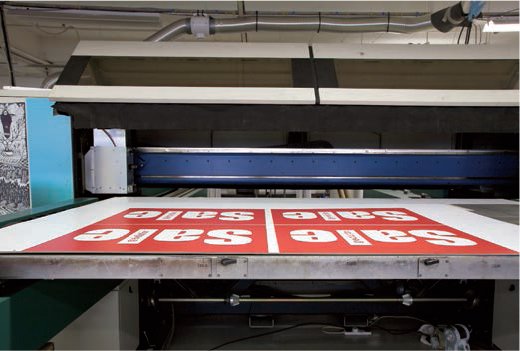
The sheet passes through the machine at 2.5 m2 (27ft2) per minute. It is, therefore, possible to print a full-width 2.5-m (8ft 2½-in) panel 4-m (13ft 2-in) long in four minutes and approximately 12 panels of this size per hour. This pass rate may seem slow compared to that of smaller plate presses but it requires no artwork preparation, or screen- or platemaking. The printed ink is immediately exposed to ultraviolet light, which dries it and chemicallly bonds it to the surface of the substrate. Here large-format ‘sale’ signs are printed four up on a sheet 2m (6ft 7in) wide.