4.2Letter-cutting stone by hand
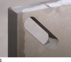
4.3Letter-cutting stone by machine
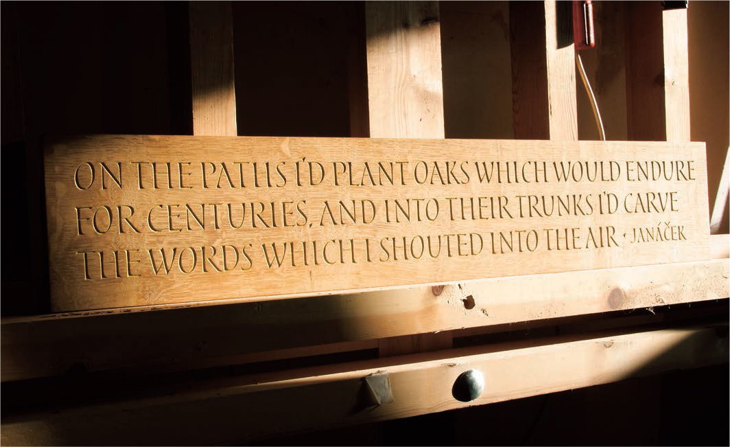
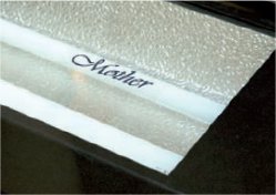
An easel in Caroline Webb’s studio supports an oak beam into which she has cut a text which references the wood. Oak is a hardwood, which makes it resistant to the paring knife. This lettering took over a week to cut.
Wood-carving has been a craft skill since prehistory, when stones, flints and bone tools were used to incise images into a surface or carve three-dimensional shapes from a log. The earliest surviving wood carvings of a script are ancient Egyptian hieroglyphics, some of which date to c.3000 BCE.
Letter-cutting in wood has always shared many principles with letter-cutting in stone (see pp.136–39), yet today many cutters tend to specialize in one or the other material. There are technical and commercial reasons why letter-cutting has developed in this way. Wood tended to be used for the exterior structures of small domestic and rural buildings, and the interiors and furniture of vast stone buildings. This division of the stone and wood carving trades accounts for the long-standing separation of letter-cutting along material lines. The division was further reinforced by the medieval guild and company system, under which nearly all carvers were trained.
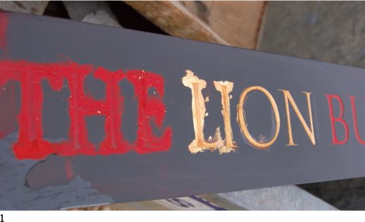
Wood proved to be a far more appropriate material for letter-cutting broken script forms (blackletter) than stone, as the thick and thin strokes of the majuscule, and the tightly spaced minuscule of Textura (see p.15), could be clearly defined. Inscriptions, which were not subject to scuffing, were painted and gilded, emphasizing their forms. The lettering was made with either a deep V-cut, or carved in relief, the face of the letter standing proud of the ground, in the manner of a woodblock print (see pp.90–91).
Caroline Webb, originally educated as a graphic designer, began to take an interest in calligraphy and carving at the University of Reading, where she was taught to cut letters by Michael Harvey (see pp.86–88). Webb, who has worked in both stone and wood, now principally works in wood, which is softer and retains the finest of lines within a letterform. Her commissions include work on memorial plaques, architectural panelling, screens, interior and exterior furniture, and gallery pieces.

1 A text carved into a bough of a yew tree. With a number of other artists Webb was commissioned to celebrate the yew. Each artist was given part of the tree to work with. The bough has been cut longitudinally, and the face sanded on both sides.

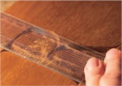
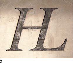
2 A detail of the letter cutting reveals the fine quality of line and the variation in the depth of cut possible in wood as compared with stone.
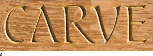
3 An inscription only 2.5cm (1in) in length from the piece of quarter-sewn oak shown opposite illustrates how the letterforms retain the calligraphic strokes through which they were first drawn. The carved serifs follow the movement of the calligraphic hand, beginning to touch the surface at the left of the apex, creating a single-sided serif falling to the left, drawing diagonally down the broad stroke with the full width of the pen and being lifted off to the right of the termination on the baseline, making a single-sided serif to the right.
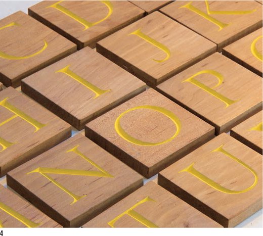
4 Details of a children's letter-cut alphabet infilled with a light ochre paint, which lifts the contrast between the letterforms and the wood.
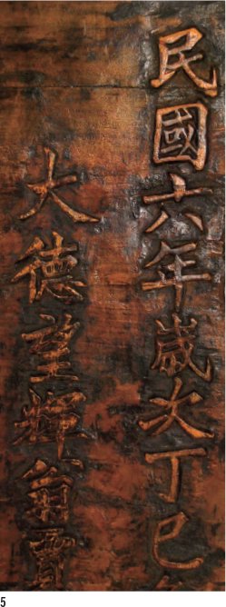
5 Relief wood-carving was a long tradition in China. Here the words happiness and long life have been carved on a sign c.1850. Like the smaller woodblock printing undertaken by Ilse Buchert Nesbitt (see p.90) the process is very time consuming as all the wood surrounding the letterform must be cut away.
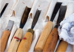
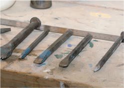
1 Letter cutters who work in wood have a large collection of carving tools. Chisels with a straight cutting edge come in different widths. Gouges are chisels with a rounded blade used for cutting away large sections of wood. The radius of the arc on a gouge varies; deeper gouges can remove more wood with a single cut. Curved gouges (below right) are used for paring (cutting away or shaving) wood in a circle.
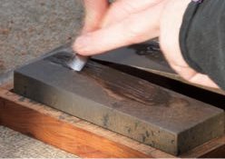
2 Wood cutting tools must be extremely sharp to create a clean cut. Here a small gouge is sharpened by the back of the blade being rubbed on an oilstone.
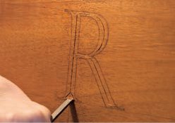
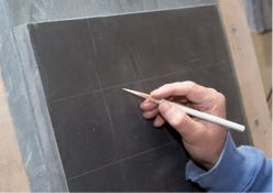
3 The letter is drawn by eye in soft pencil outline between a cap line and baseline, in the same way it would be on stone. Running the words along a plank, with the grain, ensures that the broad, deep, vertical V-cuts are cut across the grain.

4 Here Webb uses a square-edged chisel to mark the centre of the V-cut which is estimated to be halfway between the outer and inner edges of the letter, and is not drawn. The chisel is tapped into the wood using a small, round mallet. Two nicks are cut into the wood at the base of the letter at approximately 45 degrees.

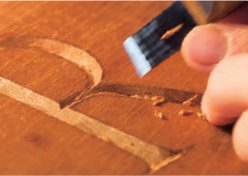
5 The bulk of the wood has been chopped out using the broad chisel to make the rough V-cut. The cut finishes inside the pencil strokes.
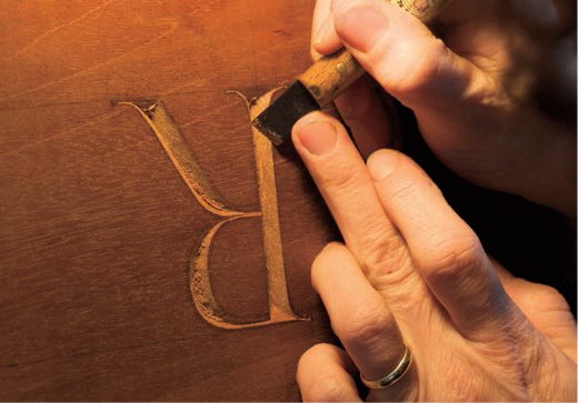
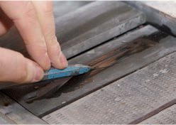
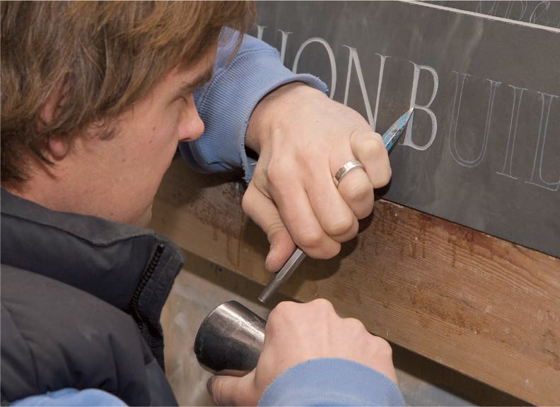
6 Here Webb has inverted the piece on an easel to work down the broad stroke of the ‘R’. Some carvers work on the refinement of a letter with fine, square chisels, but here she works with a chip or paring knife. The knife has a very short blade with a slight angle. It is worked slowly towards the carver across the grain. The blade is pushed by the handle held in the right hand and resisted by a finger of the left hand.
7 The chip knife is turned over and worked away from the carver with both hands. The left hand pushes the base of the handle and blade and is resisted by the right hand holding the handle. This twohanded cutting brings power and control to the cutting edge, and prevents the knife slipping and cutting away essential wood or creating unsightly gouges. The knife is held firmly at a consistent angle and small shavings of wood curl away from the blade.

8 Nearly all the wood has been removed from the V-cut and the edge of the cut is now very close to the pencil outline.
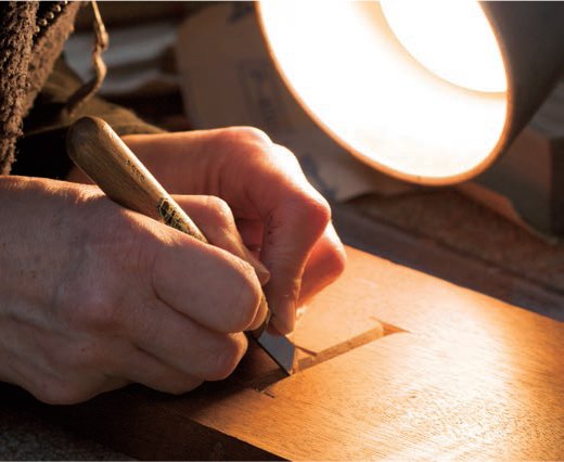
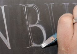
9 The piece is now laid on a flat bench and, using a chip knife, Webb pares away the final edge of the letter up to the pencil outline.
10 A straight edge is used to check that the serifs extend equally from the downstroke.

11 Layout paper is placed over the letter and a rubbing is made using a graphite stick. Viewing the letter in this flat, reversed-out graphic form reveals any tiny imperfections. On finishing a piece, some cutters take a full-size graphite or wax rubbing of the design as a record, and store both the original pencil design and the rubbing together. This allows a cutter to review his or her work over a lifetime and serves as a resource for future clients.

12 The final 7.5-cm (3-in) letter has taken about an hour to draw and cut. The crispness and precision achieved with the knife is breathtaking. Where the upper bowl joins the centre bar a very fine point has been created that has a length and refinement impossible in stone. The serifs in this letter are square-ended rather than tapering to a point.

Webb draws a design out line by line before tracing the lettering on to tracing paper. This enables her to clean up the design and centre the lines’ lettering.
4.2 Letter-cutting stone by hand
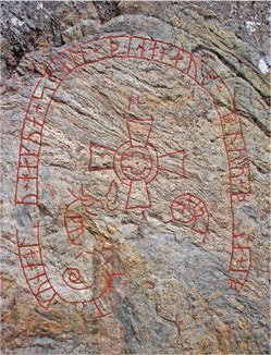
Monoline Viking runes inscribed or scratched into a stone are far removed from the earlier, highly sophisticated Roman square capitals which appear on Trajan’s Column in Rome and form the basis of what most letter cutters are taught.
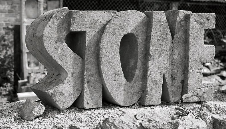
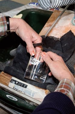
In this carving of the word ‘stone’ by Andrew Whittle the surface is not merely incised, the lettering takes on a sculptural, three-dimensional form.
In cutting stone the proportions, height to width, and line widths of the letters are determined by the letter cutter, although most cutters tend to develop an individual set of proportions for roman caps. Drawing the letters requires extraordinary skill and the techniques used vary greatly between cutters. After conducting an extensive survey of historical roman forms, the lettering expert Edward Cattich concluded that the letters were first painted on the stone with a brush. Cattich, an experienced calligrapher himself, speculated on how each roman cap was broken into its constituent strokes.
While all letter cutters recognize the innate relationship between calligraphy and their own practices, few use a brush to paint the letters on to stone. Some stone cutters use a soft, chisel-pointed pencil which enables them to draw both sides of the letter with a single stroke, while others bind two pencils together, which creates two keylines with a single movement. In letter draughtsmanship all the design issues are interlinked. The size of the letters affects the number of words per line. The arrangement – which on a traditional headstone is usually centred – affects the word breaks, and hierarchy is determined by the size, position and style of the letters. Roman caps can be considered as three groups: round (C, D, G, O, Q), symmetrical (A, H, I, M, N, T, U, V, W, X and Y) and asymmetrical (B, E, F, J, K, L, P, R, S, Z). The round letters are generally wider than the other two groups with the exception of ‘M’ and ‘W’; the asymmetrical letters are approximately half to three-fifths of the round letters. The symmetrical letters are drawn approximately five-eighths to three-quarters of the round letters. Roman letters can be drawn with vertical stress, making the ‘O’ symmetrical for example, or with a diagonal line of stress.
Watching the drawing of letters by an experienced letter cutter, it becomes clear that he or she is relying as much on kinetic memory (when muscles remember a repeated sequence) as eye. The width of each letter is individual but both the widths and the intercharacter spaces seem to be considered in combination. The guiding principle in drawing the letters is the search for consistency of letter pattern, evenness of line weight and spacing, uniformity of stress and logical word breaks. Lower-case and italic letters share all these considerations but the ascender and descender lengths and inclination must also be accommodated.

1 Two rough-hewn, Elterwater green slate pillars with a river surface stand in a pebbled landscape. The lettering, a quote from William Blake, was designed and cut by the Cardozo Kindersley Workshop, Cambridge, England.
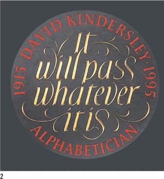
2 A memorial plaque cut in dark, Welsh slate in memory of the great letter cutter David Kindersley, by the Cardozo Kindersley Workshop. The incised caps have been infilled with red paint, as lettering was on Roman buildings. The graceful lettering with embellished flourishes is infilled with gold. The variation in the form of the italic ‘s’ shows the freedom with which a letter cutter works, considering that the lettering sits within a space.

3 Letter cutter and calligrapher John Neilson makes use of relief forms in this piece ‘Ceaseless Message’, from Rilke’s Duino Elegies, translated by Stephen Mitchell. Relief lettering involves cutting away far greater quantities of stone than incised forms, so the softer limestone of this piece is ideal. The lettering is cut in caps without interword spacing, and so stands proud of the surface as a form rather than as individual words.
1 Cold chisels (solid metal chisels designed to cut stone rather than wood) are made in many sizes. The cutting edge is now frequently tipped with tungsten carbide (a hard, grey metal compound). The large chisel (left) with several points is referred to as a claw. The tip of a chisel may be flat (centre), rounded (second from right) or form a point (right) used for pointing a stippled effect on the surface of the stone.

2 The larger, nylon-headed round mallet (left) is used for heavy work with a wide chisel, where a large quantity of stone needs to be removed quickly. The small, round metal mallet (centre) is used for carving details together with a small chisel. The block mallet (right) is generally reserved for very heavy work with a broad chisel and for splitting stone.

3 A white chinagraph pencil is used for drawing on dark stones such as Welsh slate, while a black graphite pencil is used on pale stone such as limestone or marble. The pencil is sharpened on emery paper to create a very long, fine point.
4 Some letter cutters work out the full size design on paper before redrawing it on the stone. Others, like Fergus Wessels, design directly on to the stone and redraw until they are happy with the layout and form of the letters. For cap letters, a parallel cap line and baseline are drawn across the stone with a ruler. The cap height usually estimated rather than measured.
5 Once all the letters have been drawn and the client has approved and checked the design and lettering on the stone, the fine chisel is sharpened and the cutting can begin.

6 A fine chisel with a slightly inclined (15-degree) cutting edge is used to incise the centre of the V-cut. The position of this undrawn line is estimated as half the distance between the keylines and is chased into the stone from a serif point with a succession of tiny blows with the mallet. The V-cut line is cut through the centre of the whole letter.
7 The cutter works from just inside the keylines towards the V-cut centre line, chopping away stone. The position of the V-cut must remain the same but it gradually deepens as it is worked alternately from both the inner and the outer edge of the letter. The chisel is held at a consistent angle in relation to the stone as this ensures an even depth.

8 Once the central V-cut is fully established, the cutter concentrates on refining the edge of the letter. The angle of the V is retained and tiny taps are used to hack back the cut to the drawn edge of the letter. The chisel angle determines the depth of cut; many stone cutters recognize each other’s work by the depth of the letters.
9 Depending on the type of stone used, hacking back can be a delicate procedure. Softer stone with consistent gradual size, such as slate or limestone, is more easily worked than hard stone like marble or granite which have an irregular, crystalline structure. The cutter works to the keyline, striving for a clean edge between the V-cut and the flat surface of the stone.

10 The serif on this capital ‘B’ is very fine and relatively long. The letter is visually weighted towards its base; the lower bowl is wider. The lower counter (the hollow, negative space within a letterform) is rounded where it meets the vertical stroke at the base of the lower bowl but the top of the upper counter is cut square. There is a gentle curve at the top and bottom of the letter, connecting the serif to the bowl. The angle of the central horizontal V-cut is consistent with the rest of the letter, but as the stroke is narrower than the vertical it is far shallower.
1 Some cutters consider the addition of any colour or gilt to an inscribed letter to be gauche or kitsch. Others of a less purist nature seek to use selected colour, enjoying its contrast with the stone. Where the surface of the stone is smooth, flood painting can be used. Paint is daubed or poured into the letter and allowed to dry. The surface is then cleaned with fine emery paper.

2 On dark stones such as slate the carved letter is initially far lighter in colour than the stone but if the stone is used externally the contrast begins to fade and the text loses its clarity through exposure to wind and rain. To compensate for the loss of legibility, some letter cutters infill the V-cut with a pale grey paint matched to the colour of the cut slate. Here the flood-painted letters are cleaned with wet and then dry paper.
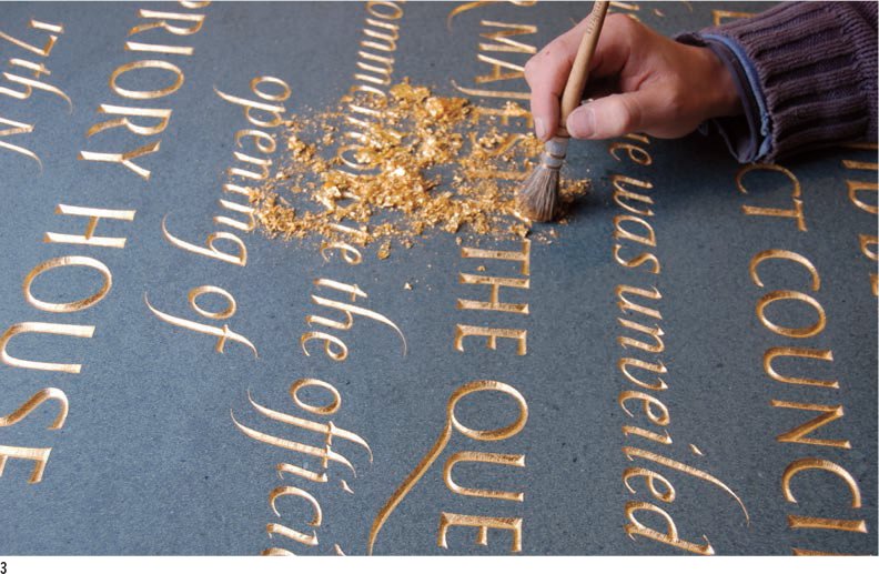
3 Gold leaf is brushed on to the incised surfaces of the letter, which has been coated with a paste. Gold comes in different colours – white and deep gold – and with different degrees of lustre (quality of shine).
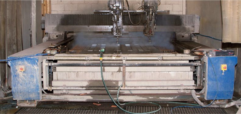
4.3 Letter-cutting stone by machine
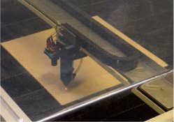
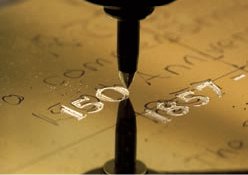
Machine letter-cutting in stone using a pantograph machine was a process invented by the Imperial War Graves Commission just after the First World War in order to make the cutting of headstones more efficient. The commission had a special font designed by the stone carver and letter cutter MacDonald Gill (1884–1947, brother of the better known Eric Gill). The pantograph process is still used today and is demonstrated here by masons at Elfes Monumental Masons in the east end of London.

One of the first pantograph letter-cutting machines developed by the Imperial War Graves Commission in 1919. Unable to hand-cut nearly a million headstones for the soldiers lost in World War I the Commission developed machine cutting by adapting the principles of machine engraving (see pp.142–43).
Cutting letters in stone using a pantograph

1 The stone-cutting machine consists of a flat wooden table on which the headstone rests. Runners on either side of the table enable the machine’s cutter to move above the surface of the stone. The mason draws a baseline, cap line and centre line in pencil on the stone for each element of the inscription. These lines, and the spaces between them, define the vertical spacing of the text. The horizontal arrangement of traditional headstones is centred, and therefore symmetrical on either side of the centre point.

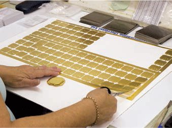
2 Engraved right-reading letter patterns, similar to those used on an engraving pantograph, are stored in a case like metal type. Each case holds 26 letters, punctuation and numerals in a single type style and size, in either caps or lower case.

3 Five-cm (2-in), 3-cm (1¼ in) and 2-cm (¾-in) caps engraved on a metal ‘slug’ of the same height. The smallest size is 2-cm (¾-in) caps, the largest 7.6-cm (3-in). Up to 3.8cm (1½in) cap heights rise by 0.3cm (⅛in) and then rise in 0.6-cm (¼-in) increments. Minimum kerning between letters is determined by the width of the shoulder on the slug (here the distance between the serif and the edge of the metal). Spacing units proportional to the cap height are based on an em square.

4 A line showing how much of the headstone will be under the ground is marked on the stone. Where the mark is made depends on the height and weight of the stone and how it will be set in the ground. Here two holes on the base have been predrilled to encase metal pins which will rise vertically from a stone beam. This type of setting requires only one-quarter of the stone to be below the surface.

5 The stone’s position on the table must be square to the cutter, centred, and with the base facing the operator before the clamps (on either side of the table) are moved into position and secured. As with type, this process is sometimes referred to as locking up. The gap between the pencil lines, where the inscription will fall, is painted with a brown, water-soluble dye on light-coloured stone and a white dye on dark stone, to make the outline of the lettering clearly visible to the operator during the cutting process.

6 The letter patterns are placed on the pattern ruler that straddles the table. This has two flanges between which the letter patterns sit. The ruler has two scales: the top is marked off in inches from left to right while the bottom edge is a centring rule, marked left and right from the centre point. A single line of text is spelt out on the rule. Once the interword spacing is fixed the pattern is centred by ensuring the distances left and right of the centre line are equal. The patterns are locked in place with quoins (wedges).
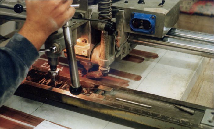
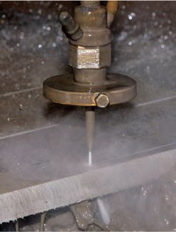
7 The cutting point can be moved up or down to accommodate different depths of headstone. The depth of cut is controlled by the amount of pressure the operator applies to the two handles used to guide the stylus.

8 The letters on this machine, unlike those generally produced by pantograph systems, are cut 1:1 – the inscribed letter is the same cap height as the pattern. The operator carefully traces the stylus around the pattern; each movement is translated directly to the diamond cutting tip. The close proximity of the pattern to the white, cut inscription, illuminated by a work light and clearly defined against the brown dye, allows the operator to monitor the quality of the cut. A suction tube sited next to the cutting head removes stone dust.

An example of the final machine V-cut showing centred lines evenly spaced using caps. The pencil centre line, baseline and cap line marks, together with the brown dye, can now be washed off. The letterforms are far more robust than those produced by hand-carving. The inscription is typographic in form, as individual characters are identical.
Letter-cutting stone by computerized machine
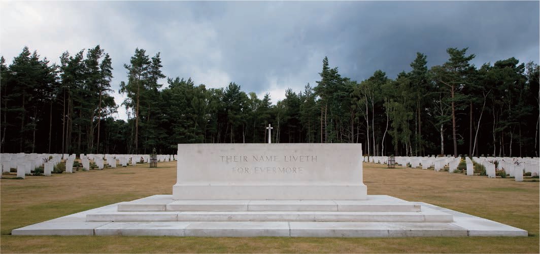
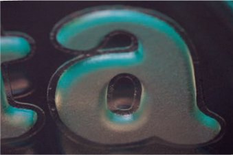
Letters cut by machine into Portland stone. The stone of sacrifice designed by Edwin Lutyens (1869–1944) for the Imperial War Graves Commission (today the Commonwealth War Graves Commission) is placed in every Commonwealth cemetery, where over 1,000 men are buried. The lettering was designed by MacDonald Gill.
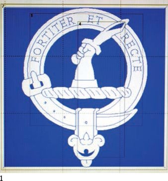
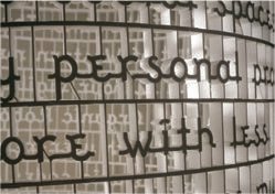
The quality of computerized cutting differs significantly from letter-cutting using a pantograph machine (see pp.140–41), by sandblasting (see pp.145–47) and by hand (see pp.136–39). A pantograph machine has no facility to vary the depth of V-cut within a single letterform; similarly sandblasting produces only profile-cut letters with no progressive variation in depth. By contrast, letter-cutting by hand can make a progressive cut with shallow serifs deepening into the strong V of the strokes and bowls. It is this progressive cut that can now be reproduced by computer-controlled cutting. The serif can be deepened towards the stroke of the letter and the node at which the returning curve of a bowl meets a stroke. For example, a cap R has two depths, a deep, vertical V is intersected by a shallow, horizontal V. The precision of the cutting is breathtaking. As every line and edge is flawless, complex patterns, crest designs and lettering can be repeatedly incised into the surface at a scale and exactness which could not be consistently equalled, stone after stone, by a letter cutter. Some older masons and letter cutters, though impressed by the precision of computerized cutting, have criticized the cut for this very exactness, arguing that it is not in keeping with the organic, natural patina of stone. No two headstones cut by hand are identical either in the surface patina, colour or texture of the stone, or in the letterform proportion or cutting incision marks. By contrast the computerized cutter produces identical crests and lettering on every stone. The respective qualities of hand, pantograph, sandblasting and computerized letter-cutting must be carefully weighed in relation to the nature of the project, the aims of the client, the spirit of the text to be cut, the type of stone used, lighting conditions, the environment in which the stone is to appear and, of course, the budget.
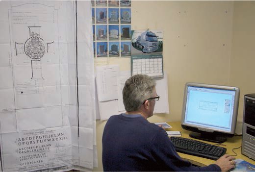
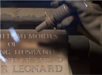
In recent years, the Commonwealth War Graves Commission has invested in very high-quality computerized letter-cutting equipment, at its workshops on the Somme in France. The machines, built in Italy, are highly specialized. The only similar machine in Britain is operated by Andrew Grassby, who also works with the Ministry of Defence, cutting headstones for service personnel who have lost their lives in conflicts since 1945. In this process the design work is undertaken on screen before the digital file is transferred to the cutter. Once set running the cutter will incise a headstone in less than one hour.
Computer-controlled machine V-cut letters
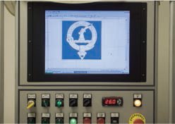
1 The lettering is arranged on screen within a scale drawing of the headstone. Unlike pantograph letter-cutting, the size and spacing can be adjusted infinitely, and cap heights are not limited to set sizes. The text in this example is centred.
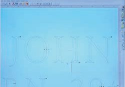
2 Unlike sandblasting, where any font or calligraphic style can be blasted into the stone, delineated by an outline, here the centre of the V-cut defines the cutting line. The centre cutting line is crucial as it literally creates the strokes, bowls and serifs. The lettering is arranged on screen. Headstones generally feature centred lettering. Letter size, and interword, character and line spacing can be adjusted.

3 Fonts for computerized letter-cutting must be designed with a three-dimensional element. For the letter to be effectively cut, the depth of cut must be varied between specific points on the cutting path. The font must be programmed with depth profiles for each of the elements. The stroke depth is the same for all, but serif and bowl depth vary.

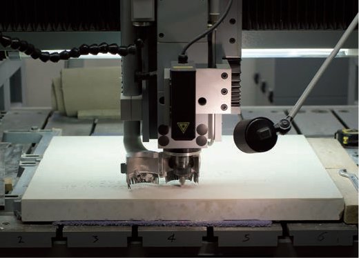
4 Once the layout of the lettering is complete it is sent directly to the cutting machine situated in a separate workshop. The machine has a large, flat bed on which the stone lies, above which is an arm holding a tungsten carbide cutter.
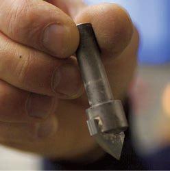
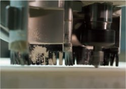
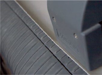
5 A detail of the tungsten carbide cutter tip. Cutters come in a range of shapes, and the machine can incise a 90-degree profile like that created by sandblasting, and produce V-cuts of different depths: 30 degrees for a shallow cut, 45 degrees for a medium cut, or, as in this example, 60 degrees for a deep cut.
6 To compensate for the stone’s minor inconsistencies in thickness a precutting program is run to form a digital, topographic profile of the surface of each stone. The cutting head has a laser (the beam is not visible) which, as it passes over the surface, continually measures the distance between the stone and the cutting tip.
7 The depth data is automatically added to, or subtracted from, the coordinates controlling the cutting depth of each letter. The operator can stop the machine and examine the cut or allow it to run the full path monitoring it remotely. The cutting time varies depending on the complexity of the design, the number and size of the characters and the hardness of the stone – hard granite and marbles are cut more slowly than Portland stone.
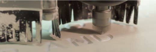
8 Each letter is cut in a single pass, and the stone dust and tiny fragments are sucked up by a powerful vacuum pump, leaving the surface clean and the letters precise. In designs with very complex imagery, or crests that require several depths of cut, the machine can be programmed to make multiple passes – cutting away stone at a single coordinate each time. As depth profiles can be developed in two planes the machine is capable of highly complex carving.
9 The completed lettering is very crisp, the cut surface consistent and the spacing even – like type the letterforms are identical. This is an intriguing contrast to more idiosyncratic hand-cut letters (see pp.136–39) and lettering by signwriters (see pp.30–39) where on occasion the form of the letters is adapted to unify the whole design.
1 The screen design of a regimental crest.

2 The same design shows that very accurate relief lettering can be cut with a 90-degree profile, vertical sides or, like letters produced for casting patterns (see pp.54–55), an inclination of 10 degrees. The last is preferable if a head stone is to stand outside vertically; it ensures surface water runs away from the face rather than collecting in reservoirs between strokes and potentially causing erosion by chemicals and frost.
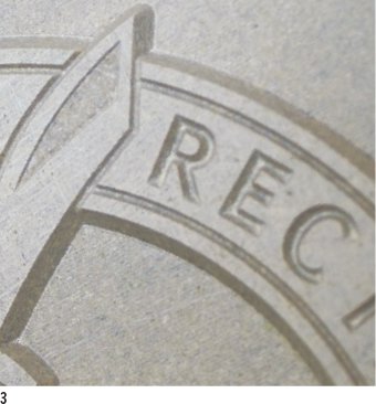
3 A detail of the machine-cut lettering shows the mechanical accuracy of the line work and the inclination.
Sandblasting is a process with many different applications. It is used for cleaning metal, brick and concrete, as an opaque finish on Perspex and glass, and as a way of producing profile-cut letters in both stone and glass. It is an abrasive procedure in which compressed air is used to fire particles of grit through a tiny nozzle. The grit erodes the surface and, with the aid of a stencil resist, cuts the letters. The letters are not V-cut but have a 90-degree profile and can be either incised or stand in relief. Sandblasting is often used on granite because the rock is very hard. It is the cheapest means of producing lettering on stone and the cutting time for a memorial may be as little as 30 minutes. On glass, sandblasting can be used for small-scale, domestic and decorative ware but the process also has larger architectural applications. Today it is frequently used in preference to hand-engraved lettering as it is quicker and produces a cleaner finish. Andrew Grassby and Lesley Pyke demonstrate sandblasting in stone and glass respectively.
Sandblasting lettering in stone

1 The text for a headstone is laid out digitally on screen according to the wishes of the relatives. Virtually any font can be sandblasted into stone. Andrew Grassby Stone- masons worked with the stone cutter and lettering artist, Michael Harvey, to produce a font called Grassby/Harvey which is frequently used by the firm for sandblasting and stone-cutting.

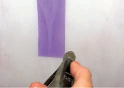
2 The cutting path controls the order in which the letters are cut into the rubber resist and determines where the knife blade on the plotter is lifted. The plotter, like those used for vinyl-cutting (see pp.124–25), consists of a rotating drum, around which the adhesive-backed, 1-mm (1⁄32-in) rubber resist turns, and horizontal tracks along which the carriage holding the knife runs.
3 A detail of the plotter’s cutting head. The lettering is cut through the surface of the rubber on the front of the pale grey backing paper and is right-reading. The cutting time is dependent on the length of the text, but the mask for an average headstone is cut within 15 minutes.

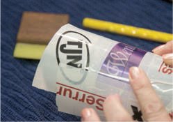
4 The backing paper is stripped away from the rubber sheet which is then laid down firmly on the front face of a prepared headstone to prevent sand scouring the surface during the blasting. Unwanted parts of the resist are removed. Incised letters must be lifted carefully with a scalpel to expose the stone beneath. The counters must be left in place. If the lettering is to be relief, the surrounding ground and counters must be removed.

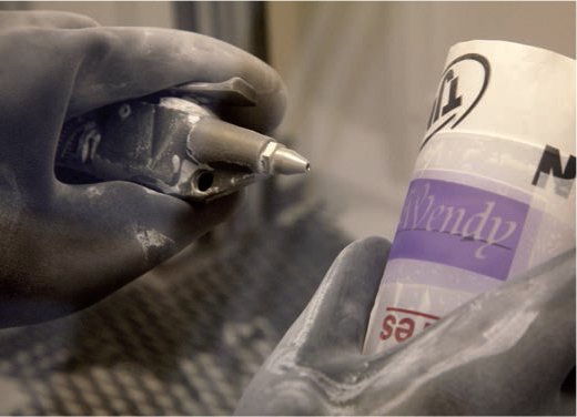
5 The sandblasting cabinet consists of an enclosed metal box with a lid and windows. The stone is lifted into the cabinet, which is sealed. Two large rubber gloves allow the operator to hold the sandblasting gun which is attached to a large compressor that supplies compressed air. The pressure is set according to the hardness of the stone. The grade of grit used, combined with the pressure, determines the depth of the cut.
6 The operator works across the surface of the stone in even sweeps so that all the exposed areas are cut to the same depth. If multiple depths are required, shallow sections can be masked out independently before deeper areas are repeat sandblasted. In about 30 minutes the lettering is 3mm (⅛in) deep. Once the lettering is of the required depth the rubber resist can be peeled away, and the stone wiped clean and polished.
Sandblasting lettering in glass

1 The artwork for sandblasting can be either hand-drawn or digital and the letterforms can be calligraphic or type. Here a piece of typesetting is run out on to film as a black positive. (It is not the artwork used in the final piece but the process is identical).
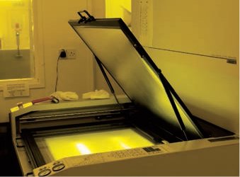
2 A mask is made as for screen printing (see pp.106–09) using ultraviolet-light-sensitive film. The film protects areas of clear glass from grains of sand that abrade the surface. It has three layers: a backing sheet and an adhesive sheet sandwich a UV-light-sensitive centre. The positive film is placed on the exposure unit with the resist film over the top.

3 The tiny exposure unit is turned on for 30 seconds, exposing the area surrounding the lettering to ultraviolet light. The backing sheet is peeled away and the light-sensitive area is exposed to a chemical developer, in a bucket. The areas exposed to the ultraviolet light are developed but the unexposed lettering is not.
4 Warm water is sprayed on to the sheet and the unexposed lettering is gently washed away, leaving a clean stencil.

5 Using a levelling stick and a felt-tip pen, the glass engraver, Lesley Pyke establishes a baseline on the glass for the type.

6 The film resist is positioned on the glass and the backing sheet is peeled away leaving the adhesive side to the glass.

7 A small squeegee (a woodenhandled nylon pad) is pulled across the surface to ensure that no air bubbles are trapped between the glass and film and that all the letter outlines are glued tightly to the glass. Any lack of adhesion will allow the sand to damage the masked surface. The backing film is gently peeled away to reveal the stencil on the glass.
8 The masking-off process is completed by wrapping the remaining exposed glass in parcel tape.

9 The glass is placed inside the sandblasting unit, which contains two rubber gloves and an air gun. The lid is closed and, using the gloves, Pyke picks up the glass with one hand and the air gun with the other. The compressor is set to a comparatively low 25psi as the glass is quite soft lead crystal. The finest sand particles are fired at the glass and pass over each letter for 20 seconds.
10 The distance between the glass and the air gun must be kept constant, as must the abrasion time for each letter. Pyke achieves consistency by counting. The used sand and glass particles fall to the bottom of the unit where they can be recycled.

11 The parcel tape is peeled off the glass and the residue film is washed away in warm water. The depth of the lettering depends on the softness of the glass, the coarseness of the sand, the air pressure (which can be run up to 50psi for very deep carving) and the abrasion time. Here the depth is 0.2mm (approx. 1⁄72in).

12 The finished glass is wiped dry and the sandblasted lettering appears as an opaque finish.

Pyke uses sandblasting in combination with acid-etching and hand-engraving to produce imagery and lettering on the surface of glassware.
A detail of the lettering shows how crisp the outline is when it is defined by the light travelling through the glass.
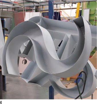
Routing uses a spinning blade called a routing bit to cut shapes into the surface of a sheet of material, or to cut directly through a material to produce letter profiles. It can be used to cut lettering from wood, metal, acrylic, plastic and nylon. Letterforms can be hand-routed by a skilled operator guiding a router around the outline of a letter, but today they are more likely to be produced by machine. Routing is used to produce large-sheet letterforms for signage and architectural and retail spaces. Routed letters can be surface-mounted as a sheet or built into a three-dimensional form to stand proud of a wall or floor. Digital keyline drawings defining the shape of each letter are positioned on a scale drawing of the sheet material. The keyline forms a cutting guide for the router; letters are positioned individually rather than as words to make the most economical use of material. The router is positioned over the work at a point called the origin point, and from here begins to cut the sheet. The computer controls the cutting speed and the path between the letters, lifting the router above the cutting surface before gently lowering the bit to cut a new letter. Once the router has been set on its path, the process is fully automated.
CNC-routed letters

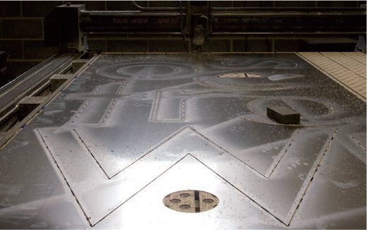
1 The operator is positioned just above the routing beds, behind a protective safety curtain that shields him or her from the metal swarf (chips or filings) thrown up by the router bit.

2 With the safety curtain drawn aside, the operator can stop the routing and examine the work. Computer-Aided Manufacture (CAM) enables a single operator to oversee several router beds running simultaneously. Here there are three: one cutting stainless steel (foreground), two cutting Perspex. A vacuum pump holds the sheets firmly on the router bed.
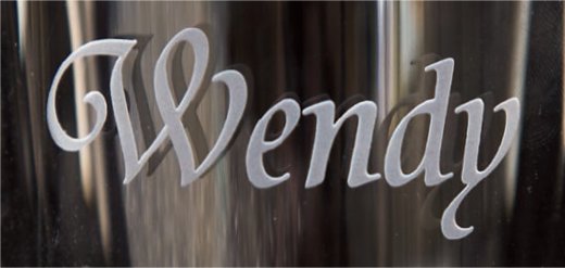
3 The largest sheet that can be cut on this bed is 3 x 2m (9ft 9in x 6ft 6in) but here a slightly narrower 1.5-m (4ft 11-in) sheet has been routed. The ‘W’ is 1.25m (4ft 1in) wide.

4 A detail of a very clean 4-mm (approx. 3⁄16-in) wide cut made in the 2.5-mm (approx. ⅛-in) deep stainless steel. Note the point of the ‘W’ (bottom left). Although the router cuts in a circular fashion (note the rounded outer corner), a perfect point has been achieved on the inner edge.

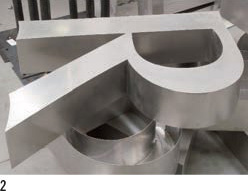
5 Large, routed letters can be fabricated into three-dimensional forms for wall mounting. Here the reverse of the letter shows how a strip giving its depth is attached with a welded seam and a support has been spot-welded.
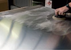
6 The front face and seams of the welded letter are cleaned off with a sanding disc.

7 A boss (a hexagonal nut with an internal screw thread) is welded to the reverse of the letter to enable wall mounting.

1 A stack of stainless steel letters with a cap height of 80cm (31½in) awaits painting.
2 A large, stainless steel ‘R’. Note how the base of the letter is refined with a very smooth arc.

3 A huge 1.2-m (4-ft) tall, 20-cm (8-in) deep stainless steel ‘T’ awaits collection. It can only be moved by fork-lift truck.
4 Letters sprayed with a grey undercoat.

5 The front face of a large display letter with its final top coat.
Water forced under very high pressure through a tiny aperture is an effective cutting agent. It is used for cutting stone, concrete and virtually any metal. Water cutting has particular engineering advantages over laser cutting and milling. As the process does not generate heat, the cut metal edge remains true and does not suffer from heat distortion or become brittle. Water cutting is capable of cutting through 8cm (31⁄4 in) of mild steel with a single pass. It does have some limitations – it only produces 90-degree profiles and is relatively slow. Small machines can cut fine letters with a cap height of 8mm (approx. 3⁄8in). Most water cutting is used for manufacturing large-scale engineering and architectural components.
Letters cut by attrition
1 Water cutting leaves mild striation on the surface of the metal but has the advantage over laser cutting of not discolouring the edge or making the metal brittle.
2 The negative letterforms cut in 12mm (approx. 1⁄32in) stainless steel…

3 … and the positive form.

1 Although water cutting is a dirty process often associated with heavy engineering, it is driven by computers. Here a series of letters 168cm (5½ft) tall and 8cm (3¼in) deep, designed to stand outside a shopping centre, have been banked together on a scale drawing of the mild-steel sheet from which they are to be cut. The keylines form the cutting path.

2 The operator links the keylines together, forming a route (blue) between those elements that require cutting (orange) and areas the jet will pass over. The origin point shows where the water jet will start its journey (bottom left corner).
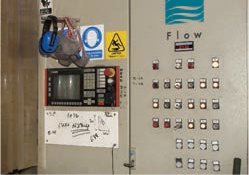
3 Water cutting uses a combination of the mineral garnet and pressurized water. The percentage of garnet (the cutting agent) to water varies for different materials, as does the speed at which the water jets travel over the surface of the material. A digital control panel allows the operator to adjust the pressure, the proportion of cutting agent to water and the speed and number of passes. Some materials are best cut in a series of shallow passes, while others require a single, deep cut.


4 (top) Tiny grains of garnet are sucked from their storage hopper into a series of pipes and moved towards the water jets. (middle) A very sophisticated compressor builds up the water pressure through a series of cylinders to 281kg per cm2 (4000lb per in2).
5 Once the route and cutting paths have been established the raw material – here a 20 x 1500 x 3000-mm (¾ x 59 x 118-in) sheet of stainless steel – can be moved by fork-lift truck on to the raised cutting bed. The jets fire down on to the surface of the metal. The standing water in the waste tank below dissipates the power of the jet and fills with metal fragments and waste garnet.

6 The small hole at the tip of the water jet determines the width of the cut. Different size tips are used for cutting different materials. Although the tips are extremely hard, they last for little more than three or four weeks as the garnet enlarges the hole and the tip becomes blunt.

7 The garnet and pressurized water combine in a chamber just above the jet to minimize machine erosion.

8 Two jets working in parallel cut a series of strips into a stainless steel sheet. The sheet is supported by a metal grating that stands above a waste tank filled with water to a depth of 100cm (39½in).
9 A detail of a cutting jet showing how the pressurized water is deflected as the cut is made from right to left. The water vaporizes into steam as it hits the metal; the noise is deafening.
10 Water from the waste tank is filtered and the clay-like sediment at the bottom is pumped out. This industrial waste is taken off site to be filtered and dried. The metal fragments are magnetically removed before being recycled.

A negative shape is left in the waste steel sheet showing how the origin point for beginning the cut has been positioned away from the edge of the letterform (bottom left) so as to produce a very fine edge.

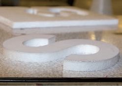
Sam Oswick built his own long-arm hot-wire cutter to make this 3-m (10-ft) polystyrene typographic tower using the typeface he designed, called Buttress which has supporting legs for the lower-case letters.
A detail shows the Buttress legs and connectives, and the modular structure of the tower, which was built in short sections.
Polystyrene was accidentally discovered in 1839 by Eduard Simon, a Berlin chemist, who distilled the resin of a sweetgum tree into an oily substance. After several days the resin had thickened and expanded into a jelly, which Simon named styrol oxide. It was not until 1959 that the Koppers Company in Pittsburgh, Pennsylvania, developed expanded polystyrene (EPS) foam.
Polystyrene foams are relatively cheap to produce and are as strong as unalloyed aluminium but far lighter. Their properties of low weight and high volume provide good buoyancy, sound and impact absorption, and excellent temperature absorption. Sheet and block polystyrene is produced in a range of densities and sizes. Standard sheets may be up to 3m (10ft) square and 500mm (19¾in) thick, while blocks are characteristically 2.5m (8ft 2in) long by 1.5m (5ft) square. Polystyrene can be cut cold using a sharp knife, which slices through the beads, or sawn by hand or machine with a very fine tooth blade. Lettering with complex three-dimensional curves can be reproduced in polystyrene by injecting pellets into an enclosed mould (see p.175), or by CAM milling. Polystyrene can be profile-cut using CAM routing (like the beads used for metal routing, see pp.148–49) or by hot wire. Hot-wire cutting involves electrically heating a steel wire to a temperature which instantly melts the polystyrene. The depth of the cut is limited by the length of the wire, while the length of the machine’s elbow determines the maximum sheet width. Since the late 1960s large-scale letters cut with 90-degree profiles using a hot wire have been very popular with designers working on museum presentations, exhibitions, advertising, theatre props, trade shows, retail displays, shop windows and carnival floats.
The Graphics Workshop, featured in the following process, is a small, specialist company that offers a range of lettering production processes for exhibitions and retail displays.
Cutting letters from polystyrene

1 The hot-wire cutter consists of a long arm and a piece of wire under tension through which an electrical current is passed. The current heats the wire and cuts the polystyrene by melting it. Polystyrene letters can be cut unfaced or faced with a colour. The unfaced polystyrene has a slightly pitted white surface, but faced lettering can be smooth and produced in a pantone colour.

2 (top) A keyline of the letter is enlarged to the correct size and printed out on a piece of paper. This guide is spray-mounted to the selected colour sheet which has a vinyl, water-resistant finish. The letter is cut along the keyline (bottom) through both layers with a scalpel.

3 The reverse of the letter is sprayed with permanent adhesive and attached to the front face of a polystyrene sheet. Polystyrene sheets can be as thin as 4mm (approx. 3⁄16in) or as thick as 150mm (6in).

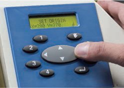
4 The machine is switched on and the wire quickly becomes hot. A cut is made from the edge of the sheet up to the letter. The slightly raised surface of the letter forms an excellent guide. The operator slides the sheet round the hot-wirecutter to the edge of the letter.
5 The completed letter has a very smooth cut finish, as the hot wire melts the surface.
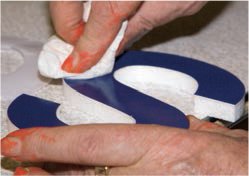
6 Turpentine is dabbed on to the front face of the paper guide loosening it from the letter. The paper guide is peeled off to reveal the coloured vinyl.
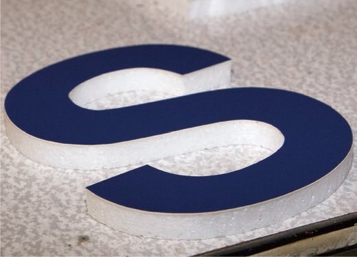
7 The remnants of the glue are removed and the clean vinyl letter is revealed. Letters can be faced with matt, silk or gloss vinyls. They can be glued or attached to a surface using crack-back paper (double-sided adhesive paper).

Laser cutting and etching is a comparatively new high-tech method of cutting profile lettering out of paper, wood, metal, plastic and fabrics. It relies on a computer-controlled laser beam burning through the material. The cutting table is completely enclosed during the cutting process.
The word laser is an acronym for ‘light amplification by stimulated emission of radiation’, a term coined by Gordon Gould, a student working on his doctorate at Columbia University in the United States in 1957. A laser is a beam of light produced by passing electrical energy into a reflective cavity containing what physicists call a gain medium (any material which increases the amplification, or power, of the light by stimulated emissions). The most simple explanation is a series of mirrors positioned around the gain medium which reflect light back and forth. With each pass through the medium the light is amplified, thus increasing its power. The repetition of this process of amplification continues until eventually the light escapes the cavity through a semi-transparent mirror and is emitted as an intense, collimated beam (the edges of the beam are parallel). The gain medium can take any state – gas, liquid, solid or plasma. The first laser used a ruby as the gain medium and is therefore referred to as a solid-state laser. Chemical lasers are powered by a chemical reaction, dye lasers use an organic liquid dye as the gain medium, while phototonic lasers use photons. Each of these types of laser has a different technical specification. Some are designed to produce very high, continuous power at a specific amplitude, and some to produce consistent, low power; others pulse, and have a variable power range or beam width.
The narrow, powerful beam of the laser is perfectly suited to recreating the line of an engineer’s digital drawing produced in a computer-aided design (CAD) program. As a consequence, heavy and light engineering firms were quick to adopt CAD and Computer-Aided Manufacture (CAM) systems in combination with laser-cutting technology for cutting fabricated parts.
Today, lasers are used for profile-cutting. Engineers realized that by speeding the pass time and not allowing the laser to cut completely through a surface, relief letters and patterns could also be laser etched (cut down in relief below the surface). The fashion industry picked up on the use of lasers for mass-producing pattern pieces in bulk and for removing pile from velvet to reproduce devoré patterns and lettering. In the last 15 years graphic designers, typographers, publishers and sign manufacturers have begun to use laser profile cutting and etching for the reproduction of many forms of lettering, environmental signs, printed ephemera, birthday cards, pop-up books and stationery. The process at Central Saint Martins College of Art and Design, London, shown here, is used in almost equal measure by graphic, industrial and fashion designers.

1 The laser is positioned and guided by a keyline drawing created from a typeface or the outline of a drawn form on a computer screen. The keyline forms a path along which the laser is guided as it traverses the cutting table. The operator assigns the order and direction in which is to travel, and can identify points at which the laser is to be turned off, automatically repositioned, and turned on again to begin a new cutting path.
2 The chosen material is positioned on the cutting bed. The origin point is set by ‘x’ and ‘y’ coordinates, through a keypad. This determines the origin point from which the laser will begin its first cutting path.
3 The cutting program is run and the laser automatically positions itself at the origin point (seen here as a red dot) and begins its first cutting path. The material used here is unfinished 6-mm (¼-in) birch plywood. More powerful lasers are able to cut thicker and denser material.
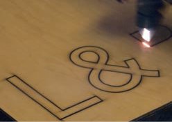
4 Guided by the keyline, the laser cuts curves, straight edges and square corners with ease. There is no physical contact between the wood and the laser tip which moves 4mm (approx. 3⁄16in) above it. Heat from the cutting process may distort or weaken some materials along the cutting edge. Laser beams vary in width, only the most expensive machines allow the operator to change beam width. Allowance for the cutting width of the beam must be made when making the scale drawing of the keyline.
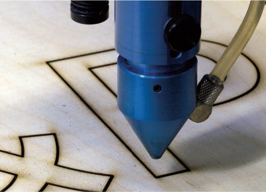
5 Only the edge of the wood is burnt through. The front face appears to be burnt at the corners but this is merely black dust particles which can easily be wiped away.

6 Once the cutting is complete, the positive letters are lifted from the sheet. The cutting process can produce stencils, negative letterforms and positive shapes equally easily. Script letterforms with many connectives are well suited to laser cutting.
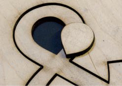
7 A detail of the counter form, which has been removed to reveal the sophisticated curves produced through laser cutting.

A laser can also be used to etch a material. The computerized keyline is used in the same way as for cutting to guide the laser over the surface but the cutting depth is reduced. The laser cuts a square section profile into the surface of the material. Even 100-gsm (3½-oz) paper can be successfully etched without the surface being punctured. The etching is burnt into the surface and is permanently dark brown in colour.
4.9 Pop-up and paper lettering
Lettering is often created on paper with drawing and calligraphy or reproduced in print; however, many artists and designers have used paper to create relief and three-dimensional letterforms through a range of techniques.

1 Celia Kilner, who works as a calligrapher and stone carver, produced this blind embossed lettering piece Deep Peace, using hand-made paper pulp pressed into a mould.
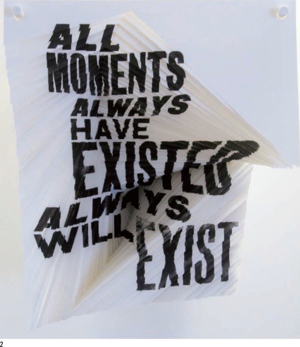
2 Illustrator Alida Sayer printed the same text on to the sheets in a stack of paper, then progressively cut away sections of each sheet. The sheets are hung slightly apart, from two long pegs, and combine to create distorted three-dimensional lettering. The quote is adapted from a line in Kurt Vonnegut’s novel Slaughterhouse-Five.
Artists and designers have used paper to make lettering impressions or pop-up forms in a variety of different ways. Pop-up letters use sheets of folded paper which are either die-cut or laser-cut (see pp.154–55) to create letterforms that stand in a 90-degree fold or rise from a sheet of paper opened through 180 degrees. Pop-up cards and books, which make use of three-dimensional lettering, became popular in the middle of the nineteenth century. New techniques, coupled with the use of pop-ups in fiction and non-fiction texts, have ensured their continuing popularity.
Pop-ups are generally undertaken by graphic designers who specialize in this form of paper engineering, working with sheets of paper, scalpel, bone folders, tape and glue. They measure, draw, fold and remould sheets until the letter rises smoothly from the opening page. The designer of a pop-up makes many developmental prototypes using different techniques and paper stocks before producing a presentation dummy and drawing a production net - a flat outline on which folds, cuts and glue points are marked. Today these are drawn digitally in software programs such as Freehand and Illustrator.
Paper pulp can be moulded into letters or formed into egg boxes and similar packaging, but lettering artists have also developed ways of moulding relief letters (see p.174) in paper pulp, allowing it to dry and retain the impression.
The first mechanical engraving machine was invented c.1798 by Nicholas-Jacques Conté. One of Napoleon’s savants, intellectuals and academics he was given the task of studying Egyptian culture and natural history during the French invasion of Egypt. He had an aptitude for mechanical devices, and realising the enormity of the task of printing images of the expedition’s findings using hand engraving (see pp.158–59) he set about making a mechanical engraving machine. His device featured a large table onto which the copper plate was locked down. The surface of the plate was straddled by a bridging arm which allowed the burin – the cutting blade – to move both horizontally and vertically, cutting lines in the copper to a consistent depth and width. By adjusting the cutting depth of the burin, the line width, and depth of engraving, and therefore the grey tone in the final print, could be varied. Between 1810 and 1820 a number of manufacturing companies in France and England added pantograph arms; a pantograph consisted of four arms linked in a ‘v’ and an inverted ‘v’ shape. Each arm can pivot and crucially the pivot points or linkages, such as the position of the stylus used for tracing the shape, and the cutting burin, can be moved. This allows a drawing or pattern to be copied same size; or, by shifting the relative position of the pivots, it can be enlarged or reduced from an original pattern. Here engraver Keith Raes uses a mechanical engraving machine to both engrave and profile-cut stencils from a pattern into brass sheets.
Machine-engraved lettering

1 The engraving machine consists of two tables connected by a pantograph (a pair of interlocking arms). A ‘pattern’ (a series of engraved right-reading letters or numerals placed in the appropriate order to spell out a word or figure, and guide the cutting point) is locked to the upper table. The ‘job’ (the piece to be engraved) is locked to the lower table.
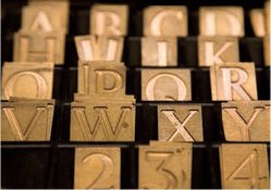
2 Engraved brass letter patterns in a range of fonts are used as guides for the pantograph. Individual right-reading letters are arranged like type to form words on the top table of the pantograph.
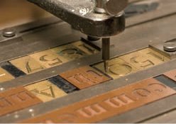
3 Blanks are used for inter-word spacing. The pantograph handle on the top table is used to trace around the inside of the letterform pattern and these movements are translated exactly to the cutting point on the lower table, but reduced at a scale of 1:10. This reduction minimizes minor irregularities or wobbles in the final cut.
4 On the lower table the cutting point revolves and is guided over the surface of the job producing a letter one-tenth the size of the pattern.
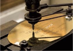
5 A detail of the engraving tip shows how the reduced letterform cut crisply into the surface of the brass sheet. The pantograph can be adjusted by resetting the length of the arms in relation to the pattern to create letters from a single guide at different sizes such as 1:20, 1:5, 1:4. Letters larger than the guide exaggerate inaccuracies.
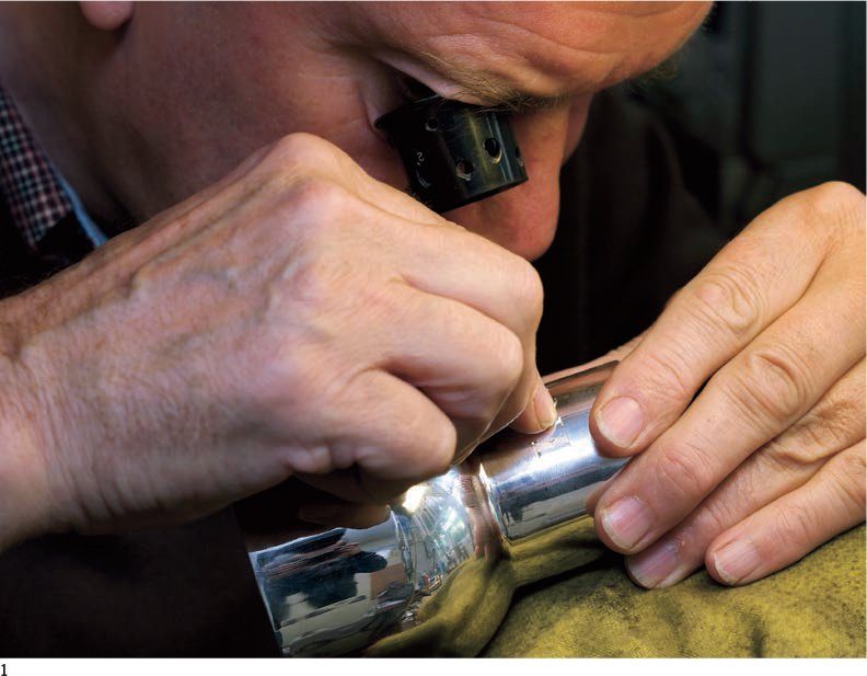
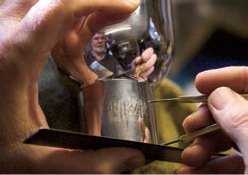
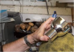
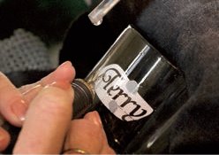
1 Master engraver Keith Raes at work on a goblet.

2 The engraver’s tool, a small gouge with a quadrangular section, is called a burin or graver. It is made in a variety of widths; the wider the blade, the deeper the cut. The back of a steel burin is rubbed against an oilstone to sharpen it, then stroked with polishing paper to create a mirror finish.
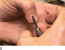
3 The quality of edge can be checked by gently running the burin across the thumb nail. If the edge picks, it is sufficiently sharp to begin engraving.

4 Engravers work extraordinarily close to the object they are engraving and use a jeweller’s enlarging eyeglass, which makes the image three or five times bigger.
Engraved letters are made by incising lines into a metal plate with a burin or graver, a small chisel-like tool with a quadrangular section. The process was originally developed to decorate precious metal objects. Throughout medieval Europe, goldsmiths and silversmiths were commissioned by the church, monarch, aristocracts and rich landowners to create ceremonial vessels, to decorate jewellery and later to produce seals and signet rings that made use of highly elaborate initials and heraldic crests. In the seventeenth and eighteenth centuries engravers began to work on decorative clocks and, later, watches. Their work was functional as well as decorative; they incised the names, numerals, increments and scale on new brass scientific instruments such as measures, rulers, thermometers, compasses and sextants. Many metals can be engraved – iron, pewter, zinc and copper – but they must be softer than the tip of the graver; the harder the metal, the greater the effort required by the engraver.
Today, although the number of skilled hand engravers has declined, the two aspects of the craft – silversmithing (decorating objects) and plate engraving (designing for print) – have survived. Apprentices are very rare and the master craftsmen of the Engravers’ Guild tend to be an ageing group. There is a sense in which the process has turned full circle and returned to its craft roots so it is now cherished by artist printmakers, private presses, silversmiths and jewellers.
Hand-engraved lettering on a silver goblet
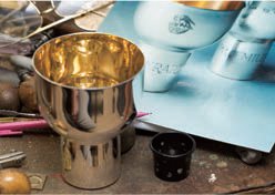
1 In this example two small, silver goblets are being engraved with the same text. The engraved lettering for the second goblet must match that of the first. By rubbing Plasticine on to the engraved letters the surface of the silver is made slightly sticky.

2 A strip of thick paper is wrapped round the first goblet, and a burnishing tool is rubbed over the lettering to transfer an impression of the letters to the paper.

3 The centre of the lettering is marked with a silver dot, and the strip of paper is turned round so that the lettering is wrong-reading. The paper is then wrapped around the second goblet. The nick is aligned with the mark and the paper impression is matched to the height of the first goblet.

4 By gently burnishing the back of the paper impression grease from the Plasticine, which has stuck to the paper, is passed to the second goblet producing a faint lustre and a legible letterform. To draw letters on to a silver piece, jeweller’s powder in a small bag is patted on to the surface and a soft chinagraph pencil used.
5 Careful measurements are required to ensure the lettering is positioned in exactly the same position on the second goblet as on the first. Here the cap height of the grease impression is checked with a pair of dividers.

6 The engraver uses a pile of jeweller’s cushions filled with soft silver sand. These support the work and lift it above the bench and nearer to the engraver’s eye.
7 A silver duster is placed over the cushions and the goblet is rested on top of it. The engraver works close up to the goblet with a magnifying eyeglass. The engraver cuts the broad, vertical stroke of the letter using three parallel lines.

8 With each cut the graver is dug into the metal surface, the hand turned down and then pushed forward. Waste metal is curled away from the surface and a sharp-edged V-cut is created.

Curved lines require greater control as both the piece and the graver are gradually turned in opposition to each other. Each cut removes metal which cannot be replaced so this is no place for mistakes. The curved cuts are run into the broad strokes. As with many hand-carving skills, the engraver seems to be cutting the letterform almost as much from kinetic memory as by eye. The deeper the cut, the greater the effort required as the metal offers significant resistance. Serifs are added last and are cut from their point towards the broad vertical stroke of the letter; they define the baseline and visually unify the lettering.

The finished lettering is polished to remove tiny burrs (rough edges) at either end of the line. The engraver seeks to keep the depth of cut consistent, the proportions of the letters regular, and the letter spacing even. The engraver takes care to place the lettering sympathetically on the piece.
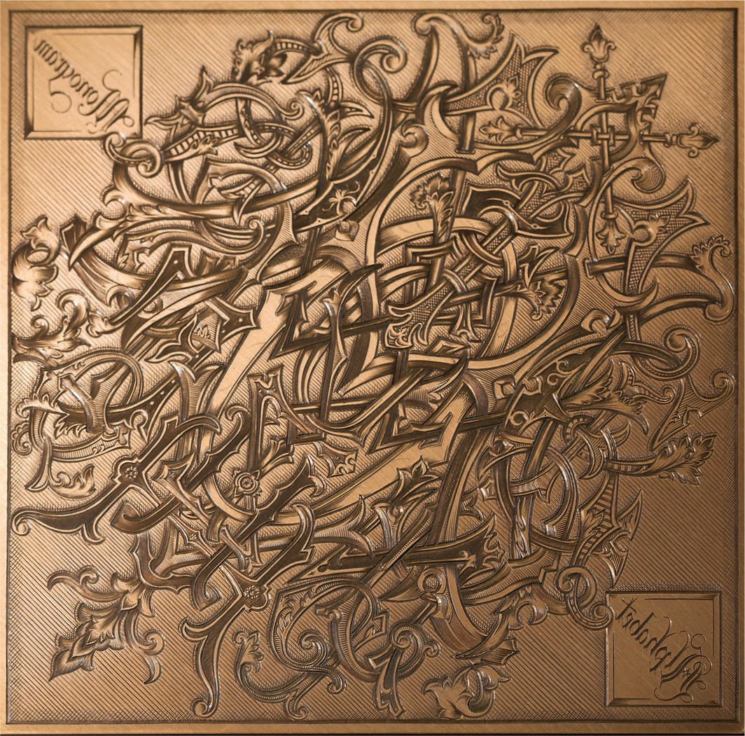
A hand-engraved, copper printing plate of an entire monogram alphabet. Raes cut this sample, using highly decorative letterforms, over two months to demonstrate the quality of hand engraving.

In the early thirteenth century, in what are now southern Germany and Switzerland, engraving was adapted so that an image could be printed on to parchment or paper directly from a copper plate. The principle of the adaption was to make the engraved image in reverse. An image or letter was drawn on to a copper plate reverse-reading and then engraved by incising lines into the surface. This engraved copper plate shows the quality of the lettering that a skilled engraver could produce.
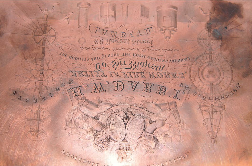
The engraving plate was polished and rolled with ink. Excess ink lying on the surface of the plate was cleaned away with a rag, leaving a residue of ink in the engraved lines below the surface of the plate. The inked plate was then placed face-up on a simple press, a sheet of paper was laid over it and pressure was applied. The moist ink was drawn out of the engraved grooves on the plate on to the paper, creating this right-reading image.

The glass engraver Lesley Pyke works at a bench with an electrical engraving tool. She wears a protective mask and glasses as small glass dust is dangerous.
Engraving images and lettering on a glass using an abrasive stone stylus is a hand technique that stretches back to ancient Roman times. Hand styli are still made but most engravers now work with an electric stylus in which a tiny abrasive stone, a burr, revolves in a small chuck (the jaws of a drill, which are tightened on the burr). This tool enables the engraver to work faster but the process is still referred to as hand engraving even though the tool revolves across the surface rather than being rubbed. There are three basic engraving depths: surface engraving, up to 10 per cent of the glass depth, intaglio or deep engraving up to 40 per cent of the glass depth (beyond this the structural integrity of the glass is threatened and is likely to break); and relief or cameo engraving where the letter is made to stand proud of the surface by engraving back the ground.

1 A hand-engraved plate with text.

2 Detail of the plate’s edge.

3 An engraved crest which combines sandblasting for the lettering and hand engraving for the image.
Hand engraving lettering on glass
1 The engraver may draw lettering directly on to the surface of a glass using a fine felt-tip pen or chinagraph pencil, or set type and use a paper pattern as a guide. A laser printout in the correct size is taped inside the glass. Here Pyke uses a simple wooden frame to clamp the glass in place.

2 The quality of the engraving is improved by wet cutting as opposed to dry abrasion. A gravity drip, a small tube that runs from a plastic bottle to a tap providing a constant drip on to the area of the engraving, is set up over the work.
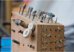

3 (top) The tiny burrs come in many different shapes, sizes and degrees of hardness and are stored in a wooden block. Burrs for cutting have tiny diamond particles that scratch the glass, while stone burrs smooth the glass. Black stone burrs take glass back to clear and rubber burrs are used to polish the glass. (bottom) A burr is set in the chuck of the electrically operated stylus.
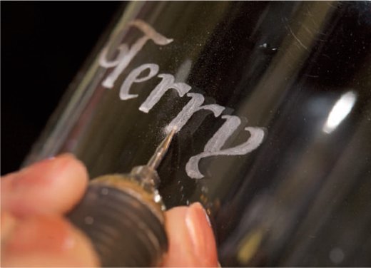
4 Some engravers work from the centre of a letterform but Pyke prefers to trace the outline using the finest 1.2-mm (approx. 1⁄16-in) point burr. The electric stylus is held in one hand and the speed is controlled with a foot pedal.

5 The outline complete, Pyke begins to work into the letterforms deepening the abrasion with a 2.35-mm (approx. ⅛-in) burr. These letters are being profile-engraved like the sandblasted ones (see pp.145–47) but hand engraving can be used to produce a progressive cut (one that starts shallow but gradually deepens).
6 It takes nearly half an hour to complete the basic lettering, which can have further decoration of different depths applied.

An enlarged detail of the engraving reveals the circular pattern within the letterform cut by the rotating burr.
The process of using acid to surface-etch lettering and imagery on glass is widely used in all areas of the glass trade. A stained-glass artist will etch individual flash glass pieces as part of a large window. Acid paste is used as an alternative to hand engraving or sandblasting for small decorative pieces, while flood etching is used to create opaque imagery and large-scale lettering on architecture. Many of the acid-etching effects created on glass used for architecture have been re-created using vinyl films (see pp.124–25), sandblasting (see pp.145–47) and screen printing (see pp.106–09). The effects of cheaper architectural vinyls may be indistinguishable from those created by etching, depending on the viewing distance, the nature of the mounting (face or reverse) and the lighting conditions. In recent years architects and interior and exhibition designers have begun to use vinyl and acid-etched glass in combination within a single scheme – the etched glass on exterior façades and the matching vinyl on interior panes – to achieve a visually unified and quality finish.
Acid etching has some unique qualities that cannot be reproduced by vinyls – principally edge lighting. Etching leaves a recess in the face of the glass, which has a return edge that can be illuminated as light passes both through the face and along the length of the glass. If the outside edge of a sheet of glass sits directly on a light source, such as a fluorescent tube, the light will pass through the glass until it reaches the etched return which it illuminates. The illuminated return line is visible from the front and reverse face. All four sides of a sheet of glass can be edge-lit with lighting that can be varied with different colour filters. Super-clear glass, with few impurities, such as Optiwhite, allows light to travel up to 4m (13ft 1in) or 5m (16ft 5in) and through butted sheets to sucessfully illuminate an etched line. Designers and artists have been able to exploit acid-etching and lighting combinations for imagery and lettering that can appear to float ethereally within the sheet.
Acid etching is used to create several different effects, depending on the type of glass and acid combination. The length of exposure to, and the strength of, the acid determine the depth of the etch, while the type and strength of the acid determine the coarseness of the finish. Strong acid produces a rougher finish than diluted acid. Transparent lettering in clear, lead glass and some low-silicate glass is produced using hydrofluoric acid followed by a cleaning process. In other glass types it is produced with combinations of strong hydrofluoric and sulphuric acid. Translucent lettering is produced using diluted hydrofluoric acid, which leaves a slightly roughened, matt surface. Acid-etched lettering with a more delicate satin finish is made by adding potassium fluoride to a mineral acid. A pearl finish is made by first coarse-etching glass using a strong bifluoride (partially diluted) mixture followed by a much diluted version of the same bifluoride, which produces two subtle layers that refract light slightly differently. A white finish is produced with an ammonium bi-fluoride mixture.
Acid-etched letters can be painted directly on to glass with a brush, usually positive translucent on clear. Colour can also be added to acid-etched lettering in glass through painting. An oil-based ink is used, mixed with ammonium bifluoride as an additional bonding agent. Similar surface effects to those produced through acid etching, vinyls and sandblasting can be achieved through screen printing, where the colours can be Pantonespecified and slightly smaller type can be reproduced (down to 12pt with reasonably robust strokes and serifs). Acid etching can be used in combination with flash glass to produce coloured, transparent lettering out of coloured or clear glass, or clear lettering out of coloured glass. In the last 30 years glass technology has advanced significantly and glass is now used in combination with clear resins with the transparent qualities of glass. It can be cold-poured and chemically cured; therefore not requiring a furnace. Resin can carry opaque colour and translucent or transparent stains which can be poured into cavities on the front or reverse face created by acid-etching.
Acid etching can be combined with gilding (where gold leaf or gold paint is applied thinly to a surface) to produce gild-etched shapes and letterforms. Throughout the nineteenth century and until the 1930s, when it fell into decline, gild etching was used on decorative mirrors, windows and shop fascias. Etched and gilded letterforms were usually produced wrong-reading on the reverse of the sheet so that the external side exposed to the elements was smooth glass. With the renewed interest in the preservation and restoration of older buildings, the skills of glass-gilding have been revived. Brewery and hotel chains, who have based their brand image on traditional values associated with craftsmanship, are using quality decorative finishes when restoring windows and mirrors. The application of gold leaf to acid-etched lettering, as well as copper and platinum gilding, is also popular for signage in the reception areas, boardrooms and offices of prestigious companies. Nero Glass have developed a range of samples using different etching techniques (see below).

1 (left) A scale drawing of a design for a glass panel to be acid-etched shows the scale relative to a figure. This artwork for the acid resist is transferred on to a screen using ultraviolet light. The resist consists of a clear or white, acidresistant oil-based ink that is screen-printed on to the surface of the glass.

2 The etching room has metal trays for simple double-sided frosting and acid benches (shown here) for flood etching. A sheet of glass with a clear resist rests on strips of old carpet awaiting the building of a small putty wall which will retain the acid pool. Note the very powerful extraction fan and the distressing of the concrete floor caused by the acid.

3 When flood etching, the acid only has contact with one side of the glass. Parts of the sheet can be isolated to create different etching depths. A sticky oil-based putty is used to create a wall to contain the acid. The white, masked area around the edge and small circles will remain clear. The diluted hydrofluoric acid will be poured on to the glass and allowed to etch for 30 minutes. The etching process produces noxious fumes, which must be sucked away by a powerful air purification system.
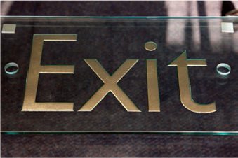
Exit sign with 8-mm (approx. ¼-in) profile etched on the reverse and infilled with paint
Satin-etching on mirror glass, sandblasted and resin infilled.
Painted front face.

Tinted resin front face

Acid-etched and white gilded.
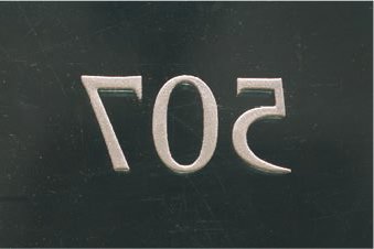
The reverse of the ‘507’ shows how the gilding sits on the surface of the letterform.
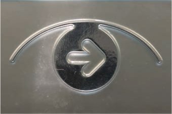
Rounded forms produced by deep sandblasting are partially acid-etched to achieve a satin finish.

Detail from an acid-etched panel. The basic panel is splatter etched (acid is dropped unevenly on the surface). The blue and black sections have been resin-infilled and the outline of the letters are gilded. The opaque inside of the word Chelsea is smooth acid-etched (evenly exposed for a consistent time).

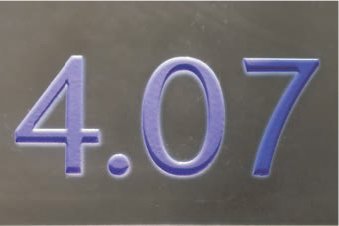
Acid-etched glass with a numeral painted on the reverse and gilding on the left.

A 2-m2 (21-ft2) acid-etched glass installation produced by Nero glass and designed by Stuart Bourne, works within a landscape. The poem by Sylvia Plath is set in Gill Sans and is clear; the acid has been applied to the opaque back of the sheet.
Photographic etching is a compound of two processes: photography and acid etching. It was originally developed in the 1970s for the manufacture of small, metal components for printed circuit boards, but has been adopted by a far wider manufacturing base, including architecture, exhibition design, interiors, graphic design and modelmaking. The accuracy of etching is ideally suited to reproducing letterforms. The process can be used in three main ways: surface etching; stencil or hole etching; and profile etching. Surface etching leaves the letters recessed below the surface of the metal. Stencil etching allows the acid to bite completely through the plate, creating a letter-shaped hole. Profile etching is the reverse of stencil etching: the metal surrounding the letter is etched away leaving the positive shape of the letter.
The artwork can be digital or paper based and is supplied by the designer. The designer specifies the type and gauge of the metal. Virtually any metal can be etched but those used most frequently are brass, copper, stainless steel, nickel silver and mild steel. Surface etching can be used on sheets of almost any thickness but is characteristically used on sheets between 0.3mm (approx. 1⁄72in) and 6mm (1⁄4in) as it is limited by a simple rule of thumb – the width of the hole should not be significantly less than the thickness of the plate. Therefore, if small type with very fine serifs is to be stencil etched it is the width of the serifs that will determine the maximum thickness of the metal plate.
Etching letters into metal

1 The process must take place in a dust-free atmosphere as any tiny particles of dust falling on the plate will be reproduced through the etching. Here metal sheets up to a maximum of 75cm (29½in) square are coated with a light-sensitive photographic resist, which is black or transparent depending on the type of metal.
2 The artwork is transferred to the surface of the plate. If the plate is to be surface etched it is exposed on one side only; for stencil or profile etching both sides are exposed. In either case a photographic negative masks the areas to be etched, which are exposed to ultraviolet light in the exposure unit.

3 The exposed metal plate is moved into the darkroom (illuminated by a safe light) and placed on a conveyor belt from where it is passed into an automatic developing machine. The resist is developed in the exposed areas of the plate and washed away in the masked areas.

4 The developing machine automatically completes the plate preparation by fixing and drying the metal sheet and rolling it out into a daylight area.

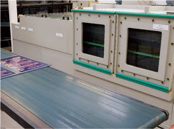
5 Like so much of this process, the etching is automated and very high-tech. Both the type of acid, and the strength at which it is used, depend on the metal and the depth of etch required. The metal sheets pass through the etching machine on a conveyor belt. The viewing windows at the front allow the operator to observe the etching as it occurs, but most of the process is monitored automatically.

6 The metal is not dipped into baths as with traditional etching but sprayed with pressurized acid. The strength of the acid and the exposure time determine the depth of the etch. Stencil or profile etching involves dissolving large amounts of metal, so sheets are sprayed and etched from both sides. The registration of the resist must therefore be exact. The reverse of the machine shows the complex system of pipes which feed the acid to the jets within.

7 Here a pile of exposed plates is interleaved with paper to prevent the surface of the resist being scratched. Any scratch or blemish would be etched into the surface of the metal.

8 The metal sheets are laid on flat carriers which travel through the etching machine on a conveyor belt. The operator feeds them through in batches.
9 The acid is only able to eat into the areas on the plate not protected by the resist. With each pass through the machine a depth of 0.2mm (approx. 1⁄72in) is etched. The metal sheets are returned via conveyor belt to the beginning of the process, where they are checked by the operator and passed through the process again until the required depth is reached.

10 When the operator is satisfied that the etch is the required depth, the sheet is passed to the cleaning area. If it has been stencil- or profileetched the components or letters are complete. The resist is washed off in a series of baths, and finally cleaned in a stream of water before being placed in an electric dryer.
11 A thin, etched sheet of brass is cut by hand with scissors before being bagged up for delivery to a client.

12 Colour can be added to the surface of the metal sheet either through screen printing or by filling in an etched recess. The infill colours use a stove-enamelling process. Colour is wiped into the recess in liquid form and the surface is wiped clean. The metal sheet is then placed in an oven and heated to 120°C (248°F), to harden the colour in the recess.

1 A record sleeve produced by Warp Records using photographically etched stainless steel.

2 The fine detail possible with photographic profile etching. Lines of 0.15mm (approx. 1⁄144in) can be etched into metal providing the steel is not thicker than the rule is wide.

3 Detail of photographically etched stencil forms.
4 An example of photo ‘engraving’. The acid does not eat through the entire plate; here the lettering has been infilled with a coloured resin.