
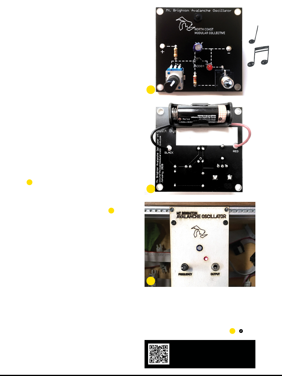
7. BATTERY
Your circuit is almost complete — except it lacks
power! In order to not have to deal with voltage
conversion, we’re using a 12V battery to provide
the juice we need. The A23 battery holder is
affixed to the PCB with a nylon screw and nut (just
finger tight is fine). In order for the holder to lay
flat against the PCB, the wires should sit within
the indentations on either side of the holder.
Trim the positive (red) and negative (black)
wires so they can comfortably reach the RED
and BLACK vias on the PCB. Strip about ¼" of
insulation from each wire with wire strippers or
cutters. Twist the braided wire so the strands
are nicely organized together, then put the wires
through the holes from the back, so they stick out
the front, where you’ll solder and trim.
8. FINISHING TOUCHES
Review your board to ensure all solder joints are
smooth and shiny, nothing is short-circuiting,
and everything is placed as indicated in Figure
J
. Next, celebrate your success by writing your
name on the white portion of the PCB! Add the
battery, with the negative side against the spring.
There’s no on/off switch, so as soon as the
battery completes the circuit (Figure
K
)
, we’re
live! The LED should be lit, and nothing should be
smoking — if either of these are not true, remove
the battery immediately to start troubleshooting.
KNOB TWIDDLING TIME!
Plug a portable speaker into the mono jack, set
the volume level, and tweak the potentiometer
knob to your heart’s content. That’s a sawtooth or
ramp wave you’re hearing; you can drive the pitch
from brappingly low to squealingly high!
Congratulations — you just created an
electronic instrument! Now that you’ve mastered
the bunny hill, you’ll be crushing double black
diamonds in no time. What’s next?
• Have access to guitar pedals or other audio
effects? Try plugging into those. Add reverb and
echo and you have instant drone music!
• See the bigger holes at the corners of the PCB?
Those can be used for standoffs or mounting it
within an enclosure of your own design.
• Want to be able to control when it makes sound
and when it doesn’t? Splice in an extension
cord and solder an arcade button for on/off.
• Synthesizer DIY folks will note that this module
uses the same voltage as Eurorack modular
synthesizers (see page 40). For advanced
SDIYers, it’s possible to modify this project to
become a Eurorack module (Figure
L
).
See and hear the Mt. Brighton
Avalanche Oscillator in action:
instagram.com/p/B9aUXT4hFFB
L
51
make.co
Joe Bauer, Nick Gaydos
J
K
M85_048-51_SS_AvalancheOsc_F1.indd 51M85_048-51_SS_AvalancheOsc_F1.indd 51 4/10/23 3:38 PM4/10/23 3:38 PM
..................Content has been hidden....................
You can't read the all page of ebook, please click here login for view all page.