
Chapter 5
Framing It

Figure 5-1. Almost all picture frames made from wood have corners mitered at 45 degrees. (Some plastic frames may be molded as a single piece.)
If you look at any wooden picture frame, I’m betting you’ll find that the corners are mitered. This means that the ends of each edge are cut diagonally so that they join neatly and symmetrically, as shown in Figure 5-1. The angle of the cut is 45 degrees, because that is halfway between 0 and 90 degrees. This is known as the miter angle. Your miter box is called a miter box because two of its slots are at 45-degree angles, to help you in making mitered corners.
On the upside, mitering looks nice. On the downside, if you are using hand tools, making a mitered frame can be difficult.
But, not impossible! In this project, I’ll show you how to make not only rectangular frames, but other shapes, too.
Your First Mitering Experience
The best way to learn is by practicing, so I suggest you use some of your square dowel to make a small frame measuring 6" x 5" along the outside edges.
In Figure 5-2, the first step is to draw two vertical lines 6" apart on your dowel. (Actual picture frames are usually sized by their inside dimensions, so that you know if your picture will fit, but for this project it’s easier to start with the outside.)

Figure 5-2. Making the measurement.

Figure 5-3. Cutting a 45-degree angle.
In Figure 5-3, the dowel is in the miter box, and the saw is in the slots angled at 45 degrees. A cam could be used to hold the wood in place, but I assume you may not have one, as many boxes are supplied without them. You can use your thumb to hold the wood, but keep your fingers away from the saw blade. Cut carefully down the outside of the vertical pencil mark, while pressing with your thumb as hard as you can, as the saw will tend to push the wood around.
Check the length of your work, as in Figure 5-4. You may be tempted to smooth the fuzzy sawn edges with some sandpaper, but sanding will tend to spoil the accuracy of the cut.

Figure 5-4. Checking the length of the cut.
Now the good news: cutting your first piece at 45 degrees automatically creates a 45-degree angle on the remainder of the dowel, so that it can be used for next section of the frame. This is shown in Figure 5-5. Just make a new measurement, and cut that section, turn it around to fit the first, and continue until you have a total of four, as shown in Figure 5-6.

Figure 5-5. Cutting one frame piece automatically gives you the correct angle for the next frame piece.

Figure 5-6. Four pieces ready to be glued and clamped—somehow!
Check that the angles fit correctly. Now for the tricky part. How are you going to glue them together?
Clamping a Corner
Ideally you want to clamp each corner so that a diagonal force presses the mitered edges together, as shown in Figure 5-7. (I have exaggerated the amount of glue, to make it visible.) The problem is, if you try to use a clamp diagonally, it won’t get a grip on the frame and will slip off.

Figure 5-7. The problem of clamping a 45-degree corner.
This problem has been around for centuries, and many methods have been devised to deal with it. Just search Google Images for clamped mitered corner, and you’ll see a great variety. But the fact that there are so many should tell you that none of them is absolutely ideal. If one method was better than all the others, no one would bother with the others anymore.
The simplest approach is to glue all the corners at once, run a strap around the outside of the frame, and tighten it. You can buy a strap specifically made for this purpose, but the cost is discouraging unless you are planning to frame a lot of pictures. The sort of ratchet strap that is sold as a tie-down for securing loads to pickup trucks or the roofs of SUVs will also work. You will want the type where the end feeds back into the ratchet. It should not terminate in a hook.
Figure 5-8 gives you the idea, and Figure 5-9 shows it working.

Figure 5-8. Using a ratchet strap instead of clamping.

Figure 5-9. A real-life ratchet strap in action.
This works well for a small frame, but because the strap doesn’t control the angles very well, a large frame may end up looking like Figure 5-10.

Figure 5-10. Hazards of applying a ratchet strap to a large frame.
There are ways to prevent this—but what are the other options?
You may be wondering why we don’t place two clamps across the frame at 90 degrees to each other, as shown in Figure 5-11. There are two problems with this arrangement. First, if you have a large frame, the clamps will tend to bend it, which will cause the mitered corners to open a little. You can overcome that by inserting some two-by-fours between the clamps and the frame sections, but the second problem is that you have to get the pressure and spacing of each of the clamps exactly right—otherwise, you end up with a situation shown in Figure 5-12.

Figure 5-11. A simple option is to put clamps across the frame at 90 degrees to each other.

Figure 5-12. This will tend to happen if the clamps are not set precisely.
Another option is to buy corner clamps, such as the one in Figure 5-13. I superimposed a white outline to show how the frame fits into this type of clamp. But to deal with all four corners simultaneously (which is the best way), you’ll need four clamps, and they are not cheap.
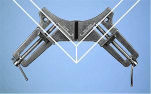
Figure 5-13. A ready-made corner clamp.
I think a good answer is to make a jig.
Making and Using a Jig
A jig is an Irish dance, but in a workshop, the word describes something that you build, to help you to align the parts in a project that you are working on. (The jig may have acquired its name because it stops parts from jiggling around.)
I try to avoid using jigs, because the time that I spend making them seems unproductive. After all, the jig has no use after the real project is done. However, a mitering jig is very simple and actually can be reused—assuming you put it in a safe place, and then remember where you put it.
My design works very much like a corner clamp, and is shown in Figure 5-14. A piece of pine, ¾" thick and 3" x 3" square, with a corner cut off, is nailed to a piece of one-by-six pine, using the same 1¼" finishing nails that were used in Chapter 4. Sections of the frame will be clamped to the square, as shown in Figure 5-15.

Figure 5-14. A simple jig to make a 90-degree frame corner.

Figure 5-15. The frame pieces clamped into position.
Making the jig is very easy. First cut 12" from the end of a one-by-six board, using the same method as in Chapter 4 (see Figure 4-9 on page 41). Now you need to remove 3" from the end of the 12" piece, again using the same method as in Figure 4-9. Set aside the remainder, which will become the base of your jig, as shown in Figure 5-15.
Turn around the piece that you just cut, measuring 3" x 51/2", and draw a line 3" from its end. Put it in your miter box, and cut along the line, being careful that the cut is very accurate, as it will be controlling the accuracy of your frame corners. If the cut doesn’t look good, try cutting another ¼" off it, as the specific size of the block that you are making is not crucial. Remember:
- n A project that you build with a jig is only as accurate as the jig itself.

Figure 5-16. Cutting a 3" x 3" square from a one-by-six board.
A plan in Figure 5-16 illustrates the three saw cuts that I just described.
One corner of the 3" x 3" square has to be beveled off, to keep it out of the way if glue squeezes out of the joint in the frame. You can bevel the corner by trimming it with a saw, or by sanding it. The precise amount is not important.
Position the 3" x 3" square as shown in Figure 5-15, hammer in a couple of nails, and your jig is ready for use. The base is not strictly necessary, but provides stability and makes the jig easier to handle.
You may wonder how the clamps apply force to the miter joint. Each clamp is exerting pressure between the frame and the center square, but not to the joint itself. This is true, but after you apply glue to the joint and position everything tightly, there is just enough flexibility in the setup so that the pressure of the clamps will push it all together, including the joint.
The only problem with this system is that if you work on one corner at a time, and you make even a small error as you add each section of the frame, the last section may not fit precisely with the first section. However, if necessary, you can sand or trim the last sections to fit.
Is this the best way to miter a frame? No, I never made that claim. My design is just simple and cheap. Also, I wanted to mention the concept of a jig, because it’s important, and will be necessary in chapters 9 and 19.
The “best” way to miter a frame is probably to spend hundreds of dollars on a gadget designed for that one purpose. But I assume you would prefer not to do that. And in any case, the gadget would be of no use if you ever want to make a non-rectangular frame—which is what I want to do now.
Non-Rectangular Frames
Take a look at the frames in Figure 5-17. Is it easy to make shapes like these? I think it is. All you have to do is transfer the miter angle, which I have shown, to pieces of wood. And I have figured out three different ways to do that.

Figure 5-17. Frames with interesting numbers of sides.
First, let’s give these things some names. The proper name for a shape that has multiple straight sides is a polygon. If the sides are all of the same length, and all have the same angles to each other, you have a regular polygon.
The names for the polygons in Figure 5-17 are:
- ■ 5 sides: pentagon
- ■ 6 sides: hexagon
- ■ 7 sides: heptagon
- ■ 8 sides: octagon
- ■ 9 sides: nonagon
- ■ 10 sides: decagon
Now that I’ve shared that bit of trivia, I’ll explain the miter angles. One way to draw angles is to buy an ancient device known as a protractor, shown in Figure 5-18. Protractors are still available in stationery stores. Draw a straight line on a piece of paper and make a mark on the line. I’m going to call that mark the origin. Align the base of the protractor with your line, and put its center mark over the origin. Now make a mark beside the number of degrees that you want. Remove the protractor, draw a line to the mark from the origin, use scissors or a knife to cut along the lines that you drew, and transfer the angle to the wood by drawing around the paper. When you use a paper shape like this, it is called a template.

Figure 5-18. A protractor.
What if you don’t want to buy a protractor? You can search for an image of one online which can be printed on paper—although this won’t be as easy to use as transparent plastic. Alternatively, perhaps you have some drawing software, and you can tell it to give you any angle you want on your computer screen. Print it, and once again, you have a template.
What if you don’t have drawing software? No problem! I wrote a little computer program that found some dimensions of triangles that just happen to have the necessary miter angles in them. Take a look at Figure 5-19.

Figure 5-19. Help in creating a miter angle.
This shows you that if you start with a rectangular piece of paper, and you measure a distance along the vertical edge named V, 128mm from the bottom-right corner, and a distance named H which is 93mm horizontally from the bottom-right corner, and connect the ends of the lines, the angle at the bottom left corner just happens to be almost exactly 54 degrees, which is the miter angle for a five-sided frame.
You can cut the triangle out of the piece of paper, apply it to the wood you are using for your frame, and draw along the diagonal line to make your miter angle. See Figure 5-21. Then you will be very, very careful to saw along the line freehand, because your miter box cannot be used for this job. It does not have a slot for 54 degrees.
The table in Figure 5-20 tells you values for V and H that will give you other miter angles. The angles will not be absolutely, totally precise, but they will be more accurate than is possible when working in the real world with hand tools. So, they are good enough.
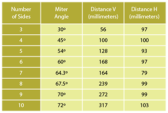
Figure 5-20. Table of miter angles, with V and H values in millimeters for drawing them on paper.
If you are wondering why I am using millimeters for these measurements, it’s for the same reason as in Chapter 4. They make measurements on paper easier than if I was asking you to use 32nds or 64ths of an inch.
What if you want to make a polygon with more than 10 sides? You’d have to figure out the miter angle yourself. Just in case you want to know, I’ll tell you how.
If your polygon has N sides, the miter angle = 90 – ( 180 / N ).
For instance, if N = 12, the miter angle = 90 – ( 180 / 12).
This would be 90 – 15 = 75 degrees.
That’s all there is to it.
Making Your Own Pentagon
To test this system, I suggest you cut a frame in the shape of a pentagon, which I have always thought is a very nice-looking polygon (even though it is also the shape of a rather large, ugly building in Washington D.C.). In Figure 5-21 I have marked 7 inches on a piece of square dowel, because I decided that this will be the external length of each side of the frame. I am using the template to show where to make my cuts.

Figure 5-21. Getting ready to cut miter joints for a pentagon-shaped frame.
Figure 5-22 shows the five frame pieces. How can you glue them together? You can make a jig, as I described before, except it won’t have a square block. You would have to make the block using the plan in Figure 5-23

Figure 5-22. Five frame pieces.

Figure 5-23. A jig for a pentagon.
The upper half of the plan in Figure 5-23 shows how to cut the jig out of a 3" piece of ¾" pine. You can create the 108-degree angles using a protractor, or using drawing software, or by putting two 54-degree templates together. Both of the red cut lines have to be at the same angle, because clamps will only work reliably if they are applied to parallel edges.
The lower half of the plan shows how the frame edges would be grouped around the jig.
If that seems like too much trouble, this is a small enough frame for a ratchet strap to work—if you have one. If you don’t, you could use a piece of thick nylon rope with a slip knot, and pull it as tightly as possible around the frame. After you pull the knot tight, you can stop it from loosening by sticking a nail or a pick through it. Avoid using thin rope or string, unless you slip in some cardboard to stop the rope from digging into the wood. See Figure 5-24. After allowing time for the glue to set, release the frame and sand it to compensate for any slight unevenness in the joints.

Figure 5-24. A pentagonal frame, roped while the glue sets.
Actual Picture Frames
I’ve been using square dowels for this project because you have dealt with them previously. An actual picture frame would have a channel cut into it, to hold a picture.
You can buy frame sections at a crafts store, but there is an alternative. You can add a thin strip of trim around the interior of your dowelled frame.
First trace the internal shape of your pentagon frame onto a piece of paper. You will need to tape two sheets of paper together, or use a large sheet, as in Figure 5-25.

Figure 5-25. Tracing the pentagonal frame onto paper.
Now you need some trim that is similar to a square dowel but only ¼" x ¼" when viewed from the end. You can find this trim cheaply in a crafts store. Line it up with the inside of the pentagon that you drew on paper, and make miter cuts in the trim.
It’s so thin and delicate, I suggest you cut it with a utility knife, as in Figure 5-26. Just push down hard while wiggling the blade a little. Cut it slightly larger than it should be, and then sand it to fit.

Figure 5-26. Cutting the trim to fit.
Now you can glue it around the inside edge of your pentagon, as in Figure 5-27. You can hold it in place using tape, or cable ties, or anything else that applies moderate pressure, until the glue sets.

Figure 5-27. Pentagon trimmed out.
Do you want glass in your frame? I’m not so sure about that. Glass is difficult to work with, and the edges are wickedly sharp.
You could use polycarbonate instead, often sold under the trade name Lexan. Just visit your local hardware store, and you can find it in small sheets, intended for replacing broken window panes. You can cut it with a saw, but I’ll come back to this when I discuss transparent plastic in Chapter 18. You may want to put the frame aside till then.
The trim in the frame will retain your polycarbonate panel and a photograph behind it. You can add a piece of cardboard at the back, which will push-fit or can be held in place with very small brads or pins. Just bear in mind that when you choose a picture to put in your frame, it should be appropriate to the shape of the frame. An example is shown in Figure 5-28.

Figure 5-28. The shape of a subject should always match the shape of its frame.
Ubiquitous Geometry
This project has been all about angles. You may feel that this is a slightly obscure topic, but understanding angles can be useful. For instance, if you ever want to frame the peaked roof of a house or the slanting roof of a shed, angles are unavoidable. Your speed square has angles marked on it for this purpose.
As for polygons—how about if you want to make an eight-sided dining table? Or a five-sided coaster? Or a six-sided jewelry box?
I once designed a 12-sided tower to stand on top of a small mountain. The tower under construction is shown in Figure 5-29. We had to bevel the framing to fit. This required me to know the miter angle, which was 75 degrees. Do you remember how to calculate that?

Figure 5-29. A 12-sided tower under construction.
Geometry is all around us. Some pots to hold pens and pencils are six-sided. You may see eight-sided windows in houses. The homes in some Native American tribes were eight-sided.
Symbols are often created with polygons. In some counties in the United States, a sheriff’s badge has seven points. A stop sign is eight-sided. A five-pointed star is a common symbol, not just in the United States but also Russia and China. The easiest way to draw that star it is to start with a pentagon.
Filling Gaps
If you make small errors in cutting frame sections, gaps will occur. What to do about this? Well, how about filling the gap with a wood filler such as Plastic Wood? This can be used by people who don’t always manage to make things fit precisely (people such as me, for instance).
Plastic Wood is sold in little cans, in a variety of colors. The colors match the wood that you are working with, so in theory, no one will notice it. Be warned, however, that if you apply polyurethane, Plastic Wood will turn a completely different color from the real wood beside it, and it won’t be invisible anymore.
Figure 5-30 shows an example of this problem. The filler was totally invisible, until after it was polyurethaned, at which point—well, you can see for yourself.

Figure 5-30. What happens to plastic wood labeled “red oak” in color, when it is applied to red oak and then coated in polyurethane.
Also be warned that Plastic Wood actually sets harder than oak. You will have difficulty removing any smears that shouldn’t be there. Other brands of wood filler are available that don’t set so hard, but I haven’t done an exhaustive comparison test.
Add it up, and your life will be easier if you can work without wood filler. One way around it is to sand your work, allowing fine sawdust to accumulate in the gaps. Wipe the dust away from the flat surfaces, but leave the dust in the gaps, and apply a quick coat of polyurethane.
Other Ideas
A Heart-Shaped Frame
Take a look at the design in Figure 5-31. Do you think you could make that? Cutting the angles would be easy, because all of them are either 45 degrees or 67.5 degrees, and those just happen to be the angles in your miter box. (In some miter boxes, the 67.5-degree miter angle is described as 22.5 degrees, for reasons illustrated in Figure 5-32.)

Figure 5-31. A heart-shaped frame using only 45-degree and 67.5-degree miter angles.

Figure 5-32. Overview of a miter box showing the 67.5-degree slot, which is sometimes referred to as being 22.5 degrees.
Clamping this frame would be a challenge, but you can make a jig as suggested in Figure 5-33.

Figure 5-33. Making a jig for the angles labeled as 135 degrees in Figure 5-31.