
Chapter 10
A Basic Box
The concept of a screw thread is more than 2,000 years old. The great Greek inventor Archimedes developed a massive wooden screw as a method for raising water from a river. Much later, in the 1800s, screws and bolts became an essential part of the industrial revolution. The modern world, as we know it, would not work without them.
This project uses screws where glue wouldn’t be as strong, and it introduces you to design issues associated with one of the world’s most basic shapes: a rectangular box.
You’ll find facts about screws in the Screws and Screwdrivers fact sheet on page 123. I’ll also mention the option to buy an electric screwdriver, but for this project, you only need a manual screwdriver with a medium-size (number 2) Phillips head.
A Screw and a Square Dowel
Before I get into the project itself, I want you to do a little wood-splitting experiment, like the one when I discussed nails in Chapter 4. You need a 3" piece of ¾" x ¾" square dowel (maybe left over from previous projects), a 3" piece of ½" x ½" square dowel, a screwdriver, and three wood screws. They can be 1" long, #10 size, as shown in Figure 10-1, although any #10 screws will do.

Figure 10-1. A screwdriver tip and screw for a wood-splitting experiment.
The #10 classification describes the thickness of the shank of the screw. In a wood screw, the shank is the smooth part directly under the head (like the smooth section of a drill bit). Unlike nails, which tend to be fatter when they are longer, a #10 screw is the same thickness no matter how long it is. You’ll find a table of screw sizes in Figure 10-34, in the fact sheet at the end of this project.
Begin with the piece of ¾" square dowel. How can you drive the screw into it? Well, you can just press hard, turn the screwdriver, and hope that the screw will cooperate—but this is not easy, especially if your dowel is hardwood.
You can whack the screw with a hammer to embed the tip of it in the wood, but a better idea is to use an awl. Set the screw aside, and push the sharp tip of the awl into the wood, about ¾" from the end. Lean on it hard, and wiggle it around to make a cavity.
Now you should find that starting the screw will be no problem, but you’ll need to use more strength as it goes in deeper, and I’m betting that the wood will split, as in Figure 10-2. Screws, like nails, do tend to split wood, especially if the screw size is relatively thick.

Figure 10-2. What happens when you force a #10 screw into a small piece of ¾" x ¾" dowel.
A #10 screw is really too big for this job. But there’s a way to make it penetrate a hardwood ¾" dowel if you really want to. You drill a pilot hole.
The Importance of a Pilot Hole
When a drill makes the hole, it doesn’t compress wood significantly. It extracts some of the wood as tiny chips. The hole then provides space for the body of the screw, while the threads of the screw, which do the real work, cut into the material that remains around the hole.
Try using a 1/8" drill to make a pilot hole for another #10 screw. If you’re wondering why I chose 1/8", a larger pilot hole would not allow the screw to get a firm grip, while a smaller pilot hole might still allow the screw to split the wood. You’ll find a table of recommended hole sizes in Figure 10-34.
Now when you insert the screw you should find that it slides in more easily and does not split the wood, but is still secure. With a 1/8" pilot hole, you can even embed a #10 screw in a skinny little ½" square dowel, as in Figure 10-3.

Figure 10-3. If you drill a 1/8" pilot hole, a #10 screw can even fit into a ½" x ½" square dowel without splitting it.
In Chapter 8, when you were building a drill rack, I suggested the option of using pilot holes with finishing nails. If you are using screws in small, precise projects, pilot holes are not just an option anymore. They are essential.
Corner Blocks
The current project is for a basic box, because the shape of a box is fundamental in fabrication work. Each of the drawers that slide out of your kitchen cabinets is constructed as a box shape. A cupboard is basically a box. Your chess set may be packaged in a wooden box. Even a bookcase is box-shaped.
Your first, basic box will be ultra-simple. The sides, bottom, and lid will be made from plywood that is ¼" thick. Small blocks of square dowel, ½" x ½", will connect the sides at the corners.
Figure 10-4 shows a rendering of the design for this box with its front side and its lid missing. Screws will be driven through the plywood and into the blocks inside the corners.

Figure 10-4. Box construction using corner blocks.
There are many other ways to make corners, and I’ll list some of them at the end of this project. But blocks are the easiest option.
Cutting Plywood
I designed this box to be small, to minimize your sawing, but I will assume that you may be starting with a relatively large piece of plywood.
When I visited my small-town local lumber yard to see what they had available, they offered me some shopworn, slightly scratched ¼" plywood with a soft pine veneer that looked as if it was guaranteed to splinter. Could I really build a small box with that? I decided I should find out, just in case you ever have a similar experience. They sold me a quarter-sheet measuring 48" x 24".
Even if you buy better-quality plywood, it often has ragged or worn edges. Therefore, it is standard procedure to make your own edges by cutting inside the edges created by the lumber company.
Figure 10-5 shows the first step. The ragged red lines indicate rough cuts, without worrying about splintering the underside of the wood, because you can’t easily use a piece of sacrificial wood under a cut that’s 16½" long.

Figure 10-5. The first two cuts are rough cuts.
Incidentally, here’s a quick tip:
- ■ If your saw tends to jam or squeal while you are making a long cut, take hold of the free end of the wood and twist it up and to the left, away from the cut, as shown in Figure 10-6. This will relieve the pressure on the saw blade. Just be careful to keep your fingers away from those saw teeth.
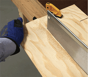
Figure 10-6. Bend the wood up away from the cut to relieve the pressure on the saw.
Now that you have a manageable work piece, you can extract three small rectangles from it. Figure 10-7 shows the cuts that will give you the first rectangle. I’ll get to the second and the third in a moment. My idea is that none of the cuts should be longer than 6", so that you can make them easily with your tenon saw.

Figure 10-7. The first of three rectangles from your work piece.
First make a clean cut along line A, about ½" inside the edge, and roughly parallel with it. The precise position is not crucial. Use sacrificial wood under the plywood as in Figure 10-8.

Figure 10-8. Cutting along line A.
After you make a nice straight cut, you can use this as your reference edge. This means you will make the next lines and cuts with reference to it. All the measurements for this project will be made relative to that edge, because the other edges were either rough-cut or factory-cut, and are not entirely trustworthy.
Now that you have your reference edge, make two marks on it that are 4" apart, as shown in Figure 10-9.

Figure 10-9. Two marks, 4" apart, on line A.
Place your speed square against the reference edge, and draw the two 6" lines that were labeled C and D in Figure 10-10. Use your pencil to make a mark at each 6" location.

Figure 10-10. Measure 6" along the lines that were labeled C and D in Figure 10-7.
Draw line B between the two 6" marks that you just made, and then extend line B out to the side edges of your strip of plywood, as shown in Figure 10-11. (Refer back to Figure 10-7 if you’ve forgotten which line is line B.) You just drew a rectangle based on your reference edge. So long as your speed square is accurate, your rectangle should be accurate.

Figure 10-11. The perimeter of the first rectangle has been outlined.
Cut along line B, as shown in Figure 10-12. When the cut is done, set aside the remainder of your work piece, rotate the rectangle that you are working on, and lines C and D are now short enough to be cut edge-to-edge with your tenon saw. Remember to cut outside the pencil lines at each step.

Figure 10-12. Cutting along line B.
Retrieve the remaining portion of your work piece, which will enable you to make your second rectangle. In Figure 10-13, you’ll see that line B is your new reference edge. Make two marks on it, 3" apart. Then you can use your speed square to draw lines for cuts E and F, each 5½" long. Then draw line G and cut along it. Finally cut E and F. This is the same system that you used for the first rectangle.

Figure 10-13. Laying out the second rectangle.
In Figure 10-14, you see the third step in your procedure. When you complete it, you should have the three rectangles shown in Figure 10-15.

Figure 10-14. Obtaining the third rectangle.

Figure 10-15. The three rectangles.
You see, now, why I didn’t suggest making a bigger box. There’s quite a lot of cutting involved. But you’re not finished yet: you need to make a second, identical set of three rectangles (because a box has six sides, assuming it includes a lid). Retrieve your original sheet of plywood and repeat the steps beginning with the rough cuts shown in Figure 10-5.
After you have your six pieces of plywood (two of each shape), you need four pieces of ½" x ½" square dowel, each 3¼" long. You can use the miter box to cut these sections.
Drilling the Plywood
Figure 10-16 shows your ultimate objective: the box, seen from below. I used contrasting colors for the front, side, and bottom pieces, to match the colors in Figure 10-17, which shows two X-ray views revealing the locations of the screws. You can see that it’s important to avoid having screws running into each other from different directions.
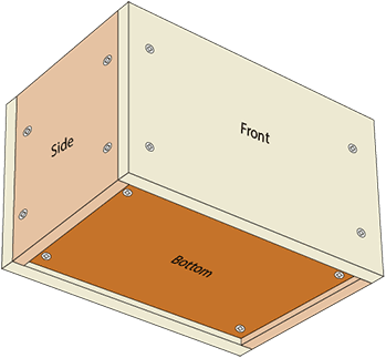
Figure 10-16. A rendering of the finished box, seen from below.

Figure 10-17. An X-ray view revealing the locations of screws.
Don’t worry if you find the plans confusing; everything will make sense when you assemble the pieces.
The locations for screw holes in the five sides of the box are shown in Figure 10-18, Figure 10-19, and Figure 10-20. (The sixth side of the box is the lid, which is not screwed into place, because it is removable.)

Figure 10-18. Screw hole locations for the ends of the box.

Figure 10-19. Screw hole locations for the front and back of the box.

Figure 10-20. Screw hole locations for the bottom of the box.
You can print or draw the plans on paper, and then transfer them to the plywood pieces by pricking through with an awl. Alternatively, you can make measurements directly on the wood, but you’ll still need to prick the drilling locations with the awl.
Use a 5/32" bit to make the holes in the plywood, which have to be big enough for the shank of each screw. These holes go all the way through, so clamp a sacrificial piece of wood under the plywood to prevent splintering where the drill bit breaks through.
When you’re starting each hole, run the drill very slowly and press the bit very lightly. A small drill bit should not normally chew up the plywood, but if your plywood has a pine veneer as soft as mine, it can happen.
If you want to do the best possible job, you can prepare for each hole with a countersink, using the technique that I described on page 97 in Chapter 8. But bear in mind, you also need to use the countersink on each hole after you drill it, to bevel it so that it will accept the angle of the screw head. Apply the countersink until the bevel is just a little wider than the diameter of a screw head.
Drilling the Dowel
In the pieces of dowel, you will use a 3/32" bit to create pilot holes. You only drill into two sides of each dowel, as shown in Figure 10-21. I included an extra 3D view in case the plan isn’t clear.

Figure 10-21. Pilot hole locations in a dowel.
The holes do not go all the way through the dowels, and must be 3/8" deep. Put a little piece of masking tape around your drill bit at the 3/8" mark, as shown in Figure 10-22, so you will know when you have reached the depth limit.

Figure 10-22. Drilling pilot holes, with masking tape around the 5/64" drill bit showing the depth limit.
This is not the only way to measure and align pilot holes, but I’d like you to do it this way in this project. The reasons will soon be clear.
Don’t bother to make pilot holes in the ends of the square dowels.
If you are wondering why the screw holes are larger than the pilot holes, Figure 10-23 provides an explanation. The screw threads are not supposed to grip the plywood (labeled A in the diagram). They grip the dowel, and the head of the screw pulls the plywood down against the dowel, while the smooth shank at the top of the screw rotates freely. This is why wood screws have a smooth section at the top. (Or at least, they used to. I’ve noticed that some so-called wood screws are now being made without the smooth section.)

Figure 10-23. How a screw works.
The box under assembly is shown in Figure 10-24. When you attach each dowel, make sure that it’s the right way around, so that its remaining holes are visible and ready for the next piece of plywood. Because each dowel is symmetrically drilled, you can turn it upside-down to expose the remaining holes if necessary. If the sides of the box are not quite aligned with each other, you can sand down the high edge later.

Figure 10-24. Assembly in progress.
After you make the front, back, and sides, you may have to sand the edges of the base of the box to make it fit. Once you have it in place, drive the screws in at each corner. I don’t think you’ll need pilot holes, as the screws are going into the end of the grain.
The lid may be tight until you sand it. Once you have it fitting neatly, I suggest a piece of round dowel as a handle, although a piece of square dowel will do just as well. Draw an X between the corners on the underside of the lid, to find its center. Then use one more screw to hold the handle in place—or glue it, as you wish. I happened to have a piece of ¾" round dowel left over from the Swanee whistle project, and I rounded the top of it just for fun. See Figure 10-25.

Figure 10-25. The box, completed.
Imperfections
I’m guessing that your box will not be perfect. I think this is the most important lesson to learn from this project: no matter how careful you are, screws and drill bits tend to wander away from where they should be, tiny errors tend to accumulate, and the next thing you know, one side is higher than the other, or a guide hole doesn’t align with a screw hole.
In future projects I’ll be mentioning ways to minimize these errors, or to make adjustments as you go along. But you may be wondering if most of the measurements are even necessary. Can’t you just put the screws approximately where they should go?
You can—but what will you do if something goes wrong, such as two of the screws bumping into each other inside one of the dowels? I think drawing a plan saves time in the long term, and if all the measurements are accurately made, the result looks better, too.
Vector graphics software is ideal for drawing plans. This is one reason I urged you to install OpenOffice Draw, back in Chapter 6. Very often, the software shows you errors that would have ruined your project if you started to build it without planning it properly.
Improvements in Corner Design
This box was an exercise, not a thing of beauty. Leaving aside the problem of building it precisely, how could the design be made better? In Chapter 16, I’ll show how to make a better box out of plastic. But using wood, I see three areas for improvement.
- 1. The blocks in the corners are unattractive and occupy space.
- 2. Cheap plywood doesn’t look nice.
- 3. The screw heads are visible, and they don’t look nice, either.
Hiding the Screw Heads
One way to hide the screw heads is by covering the exterior of the box with veneer, so long as the heads are flush with the plywood, or slightly recessed. Veneer is a very thin layer of wood with an attractive grain pattern. You can attach it with contact adhesive. The same concept is used in kitchen counter tops, where particle board is covered with a laminate such as Formica.
But veneer is expensive, and is not easy to use.
You can, of course, recess the screw heads and then conceal them with caulk, plastic wood, or some other filler. Smear some more onto the edges of the plywood, and then paint the box. This would take time and trouble, and I suspect that joints between the sections might still be visible under the paint.
The most elegant solution is to frame each side of the box. The frame would consist of square dowels, each measuring maybe 3/8" x 3/8", with a groove cut in their inside edges. Very thin plywood would slot it into the grooves. I like the way this looks, but it isn’t quick or easy.
An easy alternative would be to use decorative screws. Chrome-plated round-headed screws are shown in Figure 10-26. You wouldn’t countersink the wood, if you were using these.

Figure 10-26. Decorative chrome-plated round-headed screws.
Other types of screws have a miniature threaded socket in the head. Dome-shaped or button-shaped accessories screw into the socket, transforming a defect (the screw head) into a feature (the dome concealing it). Screws of this type are sometimes used to hold a bathroom mirror onto the wall.
However, the best way to get rid of visible screws is by not using any screws at all. What are our options, there?
Materials
To hide the edges of the plywood at the corners, you could miter the corners. To avoid using screws, you could then glue the plywood to the interior blocks. But cutting and joining thin plywood precisely at 45 degrees is not easy, and in any case, the top edge of the plywood would still be visible.
The edges of natural wood are nicer to look at. While you have seen that thin wood breaks easily when flexed parallel with the grain, the sides of the box shouldn’t be under much stress. Many options are available for corner joints using natural wood (see below).
Alternatively, you could get away from wood altogether, and use ABS plastic, making the corners by bending them. I’ll be showing you how to do this in Chapter 15.
Losing the Blocks
If you switch to natural hardwood, and if you make the sides of the box thicker, there are dozens of ways to create corners. Here are some common ones.
Square-Ended Butt Joint
The most basic configuration simply butts one piece against another and glues them together. This isn’t very strong, but is quick. See Figure 10-27. (I suggested this method for making the corners of the frame for Dad’s Puzzler, in Chapter 1.)

Figure 10-27. The most basic corner joint.
Dowel Joint
Small round dowels, which I usually think of as pegs, can strengthen a butt joint. In Figure 10-28, pegs have been inserted in one panel, and will be glued into matching holes in the other panel. You’ll find this method in the very next project, to build a bookcase.

Figure 10-28. Dowels inserted to strengthen a square-ended butt joint.
Mitered Butt Joint
The joint that I have been referring to as “mitered” is really a mitered butt joint, meaning that the flat surfaces butt together. See Figure 10-29.

Figure 10-29. Mitered butt joint.
Mitered Reinforced Butt Joint
A groove can be cut in each mitered surface, and a thin rectangle of wood can be glued into it—assuming you have the right kind of tool to cut the grooves. See Figure 10-30. This type of reinforcement can be added to other types of joints.
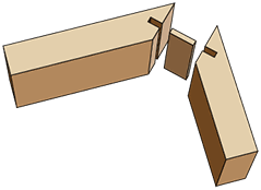
Figure 10-30. Mitered reinforced butt joint.
Rabbet Joint
Because glue is more powerful when it is applied to two surfaces at 90 degrees, a rabbet joint is stronger than a plain butt joint. See Figure 10-31.

Figure 10-31. Rabbet joint.
Corner Lipping
A section can be added to the corner to conceal the edges of the wooden panels. The section can be rounded, as shown in Figure 10-32, or can have a square cross-section, or ornamental shape.

Figure 10-32. Lipping.
Many more joints exist, because people have been thinking of ways to deal with the basic problem of connecting pieces of wood at 90 degrees for hundreds of years. Search Google Images for board joints, and see how many you find. I’m not listing them here because many, if not most, require power tools or special hand tools to cut the necessary shapes in the wood.