
Chapter 4
Organic Modeling
Organic modeling uses the same basic tools required for hard modeling. However, the demand on the tools is greater. Organic-looking surfaces are much harder to generate than most factory-built objects. Organic surfaces require nature’s imperfections and long continuous surfaces that blend back into themselves.
This chapter focuses on creating the base shape of a generic human female—generic because the main goal is not to model specific details of an individual but to convey proper edge flow and structure that can support anatomy. Following these principles will allow you to adapt the methods to create other life forms, such as a quadruped or alien.
In this chapter, you will learn to
- Implement box modeling
- Employ build-out modeling
- Sculpt polygons
- Use retopology tools
Implement Box Modeling
Box modeling is the technique of using the polygon-modeling tools to shape a basic cube into a more complex object. Once the form is established, you can add more geometry to create detail. Over the years, as computer power and modeling tools have improved, the box model has also evolved into a more rounded shape. To begin a human form, you will start with a smoothed cube. This allows you to pull out the necessary amount of geometry for good surface flow.
Surface flow refers to the orientation of your polygon edges. Ideally, you want to have uniformly spaced edges or polygon faces of equal size. Your edges should be perpendicular to each other, creating square faces. Poor surface flow can result in poor deformation. The fewer the polygons, the more important surface flow becomes.
The best way to start is to create some orthographic drawings based on the sketch. You can use these as a guide in the Autodesk® Maya® software to ensure that the placement of the model’s parts and the proportions are consistent. Sometimes the concept artist creates these drawings for you; sometimes you need to create them yourself. (And sometimes you may be both modeler and concept artist.) When creating the drawings, it’s usually a good idea to focus on the major forms, creating bold lines and leaving out most of the details. A heavily detailed drawing can get confusing when you’re working in Maya. You can always refer to the original concept drawing as a guide for the details. Since there is only one view of the design, some parts of the model need to be invented for the three-dimensional version. Figure 4.1 shows the orthographic drawings for this project.

Figure 4.1 Simplified drawings have been created for the front and side views of the concept.
After you create the orthographic drawings, your first task is to bring them into Maya and apply them to image planes. You can do so by following the instructions outlined in Chapter 3, “Hard-Surface Modeling,” in the section “Employing Image Planes.”
Shaping Using Smooth Mesh Polygon Geometry
In this section, you’ll create the basic shape of the torso for the human character using the Extrude tool and smooth mesh polygon geometry.
- Open the
torso_v01.mascene from thechapter4scenesdirectory at the book’s web page (www.sybex.com/go/masteringmaya2016). The scene contains two free image planes, each set up with a different view of the female reference material. If the image files are missing from the scene and you get an error, you may have to remap the images onto the image planes. - Choose Create ➣ Polygon Primitives ➣ Cube ➣ ❒ and, in the resulting window, accept the default options.
- Select the cube, and name it
torso. Position and scale the torso so that it roughly matches the position of the torso in the side view. - Set the channels as follows:
- Translate X:
0 - Translate Y:
16.356 - Translate Z:
0 - Scale X:
3.782 - Scale Y:
3.782 - Scale Z:
3.782
- Translate X:
- With the cube selected, choose Mesh ➣ Smooth from the Modeling menu set. Use the default settings. Figure 4.2 shows the progress so far.
-
With the torso selected, press the
3key to switch to smooth mesh preview. The edges of the shape become rounded. With smooth mesh preview enabled, the object is essentially a sphere. - Open the Modeling Toolkit by clicking the vertical tab on the right side of the screen. If the Modeling Toolkit tab isn’t visible, you can turn it on by clicking its icon, the cube and hammer, from above the Channel Box.
- The Modeling Toolkit has a symmetry function that allows you to work on half of the model while the other half automatically updates. Click the Symmetry triangle, and choose Object X (see Figure 4.3). Object X refers to the axis across which you want the symmetry to work.
- With the Symmetry feature active, you only need to work on half of the model. This includes making selections as well. With that in mind, RMB over the geometry and choose Face from the marking menu. Select the four faces on the right, as shown in Figure 4.4.
- Switch to the front view. Select the Extrude button under the Components rollout of the Modeling Toolkit. MMB-click and drag to pull the extrusion out in the local z-axis or use the In Line Editor to increase the thickness. Pull the faces until they reach the border of the drawing (see Figure 4.5).
- Switch to the Scale tool. The hot key
rworks with the Modeling Toolkit. Scale down the extruded faces in the y-axis. The Scale tool stops automatically when the faces are flattened (see Figure 4.6). -
Switch to the perspective view, and shape the surface roughly to match the drawing. Use the Move tool to push and pull vertices. Remember, only half of the model needs to be adjusted. The Symmetry feature allows you to select a vertex from either side of the model. Figure 4.7 shows the pelvis after it has been shaped.
- Select the four faces that make up the top of the surface, as shown in Figure 4.8.
- Select Extrude and drag the extrusion to 1.0 unit. Figure 4.9 shows the relative placement for the extrusion.
- Scale the extruded faces in the x-axis to fit them with the reference material. The faces below the new extrusion might be outside the reference material shape. This is okay for now. Smooth mesh preview can cause the shape to change as you continue to extrude faces; therefore, making subtle changes this early in the modeling process may be a waste of time.
-
Save the scene as
torso_v02.ma.To see a version of the scene to this point, open the
torso_v02.mascene from thechapter4scenesdirectory at the book’s web page. - Continue with the scene from step 17, or open the
torso_v02.mascene from thechapter4scenesdirectory at the book’s web page. Look at steps 9 and 10 if you need help. - Before continuing with the torso, extrude the leg. Select four faces along the hip line. Use Figure 4.10 for reference.
- Extrude the selected faces in the local z-axis or use the thickness attribute. Use Figure 4.11 for reference.
- Translate and rotate the extruded leg to match the reference material (see Figure 4.12).
- Continue to shape the torso at the vertex level. Use multiple viewports to get the correct contours (see Figure 4.13).
- You can now focus your attention on the upper body. Select the faces at the top of the pelvis.
- Extrude the faces up to the waist (see Figure 4.14).
- You can use the Extrude tool’s In Line viewer to alter the type of extrusion. Click and drag on Offset to decrease the width of the geometry. Reduce the size of the extrusion until it matches the reference image.
- To add another extrusion, click the Extrude button from the Modeling Toolkit. Click the Thickness setting in the In Line viewer to activate the function.
- You can switch to Offset to increase the width of the extrusion.
- Press
gto repeat your last command in order to extrude another level. Raise the geometry up to the armpit. Figure 4.15 shows the progress of the torso. -
Save the scene as
torso_v03.ma.To see a version of the scene to this point, open the
torso_v03.mascene from thechapter4scenesdirectory at the book’s web page. - Continue with the scene from step 29, or open the
torso_v03.mascene from thechapter4scenesdirectory at the book’s web page. Again, look to steps 9 and 10 if you need help. - You can now extrude the shoulder. This is critical to getting proper edge flow. The direction of the geometry needs to change in order to accommodate the arm. Select the two faces, one in front and one in back, closest to the armpit.
- Extrude the faces halfway into the shoulder.
- Translate and rotate the extruded faces so that the edges are perpendicular to the length of the arm (see Figure 4.16).
- Add another extrusion to complete the shoulder. If the faces from which you are extruding are at the proper angle, you may not need to adjust the new extrusion. The goal is to have four faces that can be extruded for the arm.
- There is a large dip in the middle of the chest. Select all of the faces making up this U-shaped structure. There are six faces in total on one side. Use Figure 4.17 as a guide.
- Extrude the faces up to the start of the neck. Scale the selection in the y-axis to flatten the geometry.
- Translate the selection so that the geometry is on the shoulder line (see Figure 4.18).
-
You can now go back and shape the geometry to match the reference material. When shaping the neck area, push the vertices outward to leave four faces total to be extruded up into the neck.
- Save the scene as
torso_v04.ma.

Figure 4.2 A smoothed polygon cube placed roughly in the same position as the torso in the side view

Figure 4.3 Enable Symmetry in the Modeling Toolkit.

Figure 4.4 Select four faces on the right side of the shape.

Figure 4.5 Extrude the selected faces to match the reference material.

Figure 4.6 Scale the faces in the y-axis.

Figure 4.7 Shape the vertices of the pelvis with the Move tool.

Figure 4.8 Choose the faces at the top of the pelvis.

Figure 4.9 Extrude the top of the torso upward in the y-axis.

Figure 4.10 Select the four faces needed to extrude the leg.

Figure 4.11 Extrude the leg in the local z-axis.

Figure 4.12 Shape the end of the leg extrusion to match the reference material.

Figure 4.13 Shape the torso in multiple views.

Figure 4.14 Extrude the faces up to the character’s waist.
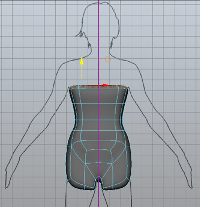
Figure 4.15 Add a couple of extrusions up to the character’s armpit.

Figure 4.16 Position the extrusion so that faces can be extruded down the length of the arm.

Figure 4.17 Select the faces in the middle of the torso.

Figure 4.18 Position the geometry to line up with the shoulders.
To see a version of the scene to this point, open the torso_v04.ma scene from the chapter4scenes directory at the book’s web page.
The surface flow for the torso is complete. The edges have been configured in such a way that adding additional edge loops will wrap around the body and contribute to the surface shape where needed (see Figure 4.19). For instance, adding a loop down the length of the left leg will create a loop that crosses over the right leg and back again. The goal is to prevent additional geometry from extending to other parts of the body in a nonsymmetrical manner. This keeps the detail local to the location to which you are adding it.

Figure 4.19 The selected faces show the geometry’s surface flow.
Multi-Cut with Edge Flow
In the previous section, you used the Extrude tool to build upon a simple shape to create a model with good surface flow. You can now insert geometry logically and not worry about edge loops spiraling out of control. When you’re using the box modeling technique, Connect Components offers some nice advantages. The following steps take you through the process of adding a leg to the character:
- Continue with the scene from the previous section, or open the
torso_v04.mascene from thechapter4scenesdirectory at the book’s web page. - If needed, establish symmetry through the Modeling Toolkit.
- Select the two edges that divide the four faces at the bottom of the leg. Shift the edges using the Move tool to center them within the leg. You want to keep the faces as square as possible.
- Select the four faces associated with the edges.
- Extrude the edges down to the character’s kneecap.
- Extrude the faces again, and drag them to the character’s ankle (see Figure 4.20).
- Choose Multi-Cut from the Tools rollout of the Modeling Toolkit.
-
Enable the Edge Flow option. Doing so tells the new components to obey the curvature of the mesh. MMB-click to insert an edge loop below the hips (see Figure 4.21).
For illustration purposes, the edge loop on the character’s right leg was added without edge flow turned on. Notice how the new loop, on the character’s left leg, actually bulges out, similar to how the leg is on the reference material. You can alter the effects of the edge flow through the Channel Box by clicking the polyConnectComponents history node. Click the words Adjust Edge Flow. MMB-click and drag in the viewport to adjust the value interactively. The value ranges from 0 to 1; however, you can type in any value, positive or negative. The default value of 1 should be sufficient.
- Save the scene as
torso_v05.ma.

Figure 4.20 Extrude faces to create the ankles.

Figure 4.21 To insert an edge loop, MMB-click in the middle of a loop.
To see a version of the scene to this point, open the torso_v05.ma scene from the chapter4scenes directory at the book’s web page.
Slide Edge Tool
Good surface flow contributes to the shape of the model. When making changes to an organic character, you often want to keep the existing shape but to relocate an edge loop. Using transformation tools, like Move and Rotate, can disrupt the shape of the surface because they cannot follow surface contours in their movement. The Slide Edge tool allows you to keep the shape while you move edges. The following steps take you through the process:
- Continue with the scene from the previous section, or open the
torso_v05.mascene from thechapter4scenesdirectory at the book’s web page. - If needed, establish symmetry through the Modeling Toolkit.
- Select the edge loop directly below the knee.
- Use Multi-Cut with the Edge Flow option selected to insert an edge loop. Figure 4.22 shows the new loop.
- RMB-click over the geometry, and choose Edge from the marking menu. Double-click to select the added loop.
- Choose Mesh Tools ➣ Slide Edge.
- MMB-click and drag the loop up toward the knee. Try to line it up with the largest part of the calf muscle on the reference material. Notice as you slide the loop that it retains the shape of the surface.
- Open the Channel Box. Click the top polyConnectComponent node under the Inputs section.
- Change the Adjust Edge Flow value to
2.0. - The Slide Edge tool remains active. You can continue to slide the edge as needed. Figure 4.23 shows the final position of the edge loop.
- Save the scene as
torso_v06.ma.

Figure 4.22 Add another edge loop.

Figure 4.23 Slide the edge loop to fit with the calf muscle.
To see a version of the scene to this point, open the torso_v06.ma scene from the chapter4scenes directory at the book’s web page.
Offset Edge Loops
Sometimes you need to add an edge loop on either side of an existing loop. The center line of the character is a great example.
- Continue with the scene from the previous section, or open the
torso_v06.mascene from thechapter4scenesdirectory at the book’s web page. - Establish symmetry through the Modeling Toolkit.
- Choose Mesh Tools ➣ Offset Edge Loop ➣ ❒.
- Select the Insert With Edge Flow option, and click Enter Tool And Close. The smooth preview mode automatically switches to smooth with cage.
- Make sure that you have multi-components or edges selected.
- Click the center line of the character. Drag the mouse to position the two new loops (see Figure 4.24).
- Save the scene as
torso_v07.ma.

Figure 4.24 Add an edge loop to either side of the character’s center line with Offset Edge Loop.
To see a version of the scene to this point, open the torso_v07.ma scene from the chapter4scenes directory at the book’s web page.
Employ Build-Out Modeling
The build-out method of modeling is similar to box modeling in that you are using the Extrude tool to create new geometry. The major difference, however, is that you start with planar geometry instead of a closed volume like the primitive cube. In this section, the character’s head is roughed out using the build-out method. As with the torso, the focus is on the tools and not on creating detail in the model.
- Open the
head_v01.mascene from thechapter4scenesdirectory at the book’s web page. The scene contains two free image planes, each set up with a different view of the character’s head. - Switch to the front view. Choose Mesh Tools ➣ Create Polygon.
- Draw a polygon around the shape of the eye. When you first start any surface, keep in mind that less is more. Try creating the shape of the eye with as few points as possible. Use Figure 4.25 as reference.
- RMB-click over the model and choose Edge. Double-click the border edge to select the loop.
- Choose Edit Mesh ➣ Extrude. Change the Offset value to
0.03. This creates the skin that conforms to the eyeball. - Press
gto repeat the last command. Another extrusion is added. - Change its Offset value to
0.05, and translate the extrusion to0.07in the local z-axis. Pulling the geometry back helps form the upper eyelid (see Figure 4.26). - The interior face of the eye is a large n-gon. Press
3to activate smooth mesh preview. Figure 4.27 (left) shows how poorly the mesh divides as a result of the n-gon. Select the face and delete it. Compare the surface shape without the n-gon on the right side of Figure 4.27. - Save the scene as
head_v02.ma.

Figure 4.25 Use the Create Polygon tool to draw the shape of the eye.

Figure 4.26 Add another extrusion to form the upper eyelid.

Figure 4.27 N-gons smooth poorly and should not be used (left). The geometry without the n-gon is much better shaped (right).
To see a version of the scene to this point, open the head_v02.ma scene from the chapter4scenes directory at the book’s web page.
Extrude along a Curve
By default, the Extrude tool uses a selected curve to extrude geometry along. The option is ignored if no curve is selected. You can extrude along a curve using edges or faces. As with most of the tools in Maya, you can modify the extrusion after you apply the tool or any time up until you delete the geometry’s history. Next, you’ll use the Extrude tool to shape the character’s laugh line:
- Continue with the scene from the previous section, or open the
head_v02.mascene from thechapter4scenesdirectory at the book’s web page. - Use the Create Polygon tool to build a single-quad face in the middle of the character’s chin. Align the face so that it sits on the positive X side of the world’s YZ plane (see Figure 4.28).
- Draw a cubic curve from the polygon’s edge, around the mouth, and up and over the nose. Use Figure 4.29 for reference.
-
Custom shapes always default to the grid plane in which you are creating them. The quad face and curve sit in the middle of the world. Switch to the side view, and align the face and curve with the reference material, as shown in Figure 4.30.
- Select the quad’s edge that you want to extrude, and then select the curve.
- Choose Extrude from the Modeling Toolkit. Use the default options. Extruding along a curve is already active.
- With only one division, the geometry is stretched from the beginning of the curve to its end. Increase the divisions to
10to follow the curve accurately. Figure 4.31 shows the divided extrusion. - The divisions are unevenly distributed due to poor parameterization of the curve. Choose Curves ➣ Rebuild ➣ ❒.
- In addition to the defaults, select NumSpans. Doing so keeps the current number of spans but redistributes them so that they will be evenly spaced. Figure 4.32 shows the corrected geometry.
- Move the eye geometry up to its position on the reference material.
- Select the laugh line and the eye geometry. Delete the history of both objects.
- Choose Mesh ➣ Combine.
- Select two edges from the eye loop and the two edges across from the eye loop on the laugh line.
- Choose Edit Mesh ➣ Bridge. The two pieces of geometry are now connected.
- Change Divisions to
2from the In Line viewer. Adding two extra divisions keeps the face size consistent with the size of the existing geometry. Figure 4.33 shows the completed bridge. - Save the scene as
head_v03.ma.

Figure 4.28 Create a single-quad face for the chin.

Figure 4.29 Draw a curve to plot the laugh line.

Figure 4.30 Shape the laugh line to match the character reference in the side view.

Figure 4.31 Increasing the extruded divisions helps the geometry follow the curve.

Figure 4.32 Rebuild the curve using the same number of spans in the curve.

Figure 4.33 Use two divisions for the bridge.
To see a version of the scene to this point, open the head_v03.ma scene from the chapter4scenes directory at the book’s web page.
Building each landmark of the face and then connecting it to existing geometry helps maintain good surface flow. It also permits finer control and allows you to work on isolated local regions. You do not have to worry about added geometry having a negative impact on another area. You can test configurations and densities prior to bringing the pieces together. Using these techniques, you can build the entire head.
Sculpt Polygons
Once you complete the base mesh, you can start adding specific detail to your model. Pushing and pulling a single vertex is time consuming and often leads to lumpy-looking surfaces. Maya offers several ways to deal with groups of components.
Soft Select Tool
Soft Selection is an option that you can use with the regular transformation tools. Move, Rotate, and Scale have rollout options in the toolbox to control various aspects of the Soft Select tool. The Modeling Toolkit also offers these options. Let’s look at some common uses and functionalities of the tool:
- Open the
female_v01.mascene from thechapter4scenesdirectory at the book’s web page. - Select the geometry and focus the camera on the character’s middle finger. RMB over the model and choose Vertex from the marking menu.
-
Choose the Move tool. In the Modeling Toolkit, expand the Soft Selection rollout and choose Soft Select.
When you choose Soft Select in any of the component selection modes, the surface turns yellow and black. The colors indicate the strength of the tool’s falloff. The falloff is dictated by the curve in the graph of the Soft Selection rollout.
- You can change the radius of the Soft Select falloff through the numeric input box above the graph. Set Falloff Radius to
0.10. - As you move your mouse, the falloff radius travels across the surface. Position the mouse over the middle finger. Notice how the falloff extends to other fingers (see Figure 4.34, left). This is a result of using the Volume falloff mode.
-
Change the falloff to Surface. Soft Select now obeys the surface, removing any effect that it had on the other fingers (see Figure 4.34, right).
You can use the hot key
band LMB-drag to change the falloff radius interactively.

Figure 4.34 Volume falloff mode (left) versus Surface falloff mode (right)
Sculpting Tools
![]()
Harnessing the power of the Autodesk® Mudbox® software, Maya has a new set of sculpting tools. If you are already familiar with Autodesk Mudbox, you will find Maya’s sculpting tools to be almost identical. All of the brushes and features have been ported over. You can access these tools through a new Sculpting Shelf or through Mesh Tools ➣ Sculpting Tools.
A graphics tablet is required to access all of Maya’s sculpting functions. Utilizing a tablet allows you to use pressure sensitivity in order to control the depth of your sculpting stroke. Maya also supports multi-touch devices for gestural input. If these are unavailable, you can still use a standard three-button mouse, but pressure sensitivity is not supported.
All of the sculpting tools have the same properties with only a few minor differences between them. You can double-click a sculpting tool icon to adjust its properties. The following is a description of the common functionality shared by the tools:
Brush The Brush section controls the core functions of the chosen sculpting tool. You can change the size of the sculpting brush (in world or screen space), the strength of the brush, and whether or not you want to mirror the tool’s effects across your geometry. This is also where you can steady your stroke based on a distance value. When sculpting, you often need to remember the size of your brush based on a specific sculpting tool. The thumb tack in the upper-right corner, after the Size slider, forces Maya to remember the brush size for a particular tool (see Figure 4.35).

Figure 4.35 The Brush section controls the main functionally of the sculpting tool.
Falloff Falloff controls how the brush strength diminishes from the center of the brush to its outer edge. The sculpting falloff operates the same way that the Soft Select falloff works (see Figure 4.36).

Figure 4.36 The Falloff controls
Stylus The Stylus rollout controls the brush sensitivity. These settings will only have an effect if you are using a graphics tablet or multi-touch device.
Stamp The Stamp rollout allows you to use a grayscale image to influence the intensity of the current sculpting tool. Dark values decrease the strength of the brush while white values apply the brush’s full strength. Stamping is incredibly powerful, allowing you to customize your sculpting tool to fit the look of any image. Figure 4.37 shows a grayscale image on the left and the resulting sculpting stroke on the right.

Figure 4.37 You can create unique sculpting tools with the use of stamps.
Display Display affects the look of the brush or the look of the geometry on which you are sculpting. These settings do not affect how the sculpting tool influences the geometry.
To see the sculpting tools in action, watch sculptingTools.mov from the chapter4movies directory at the book’s web page.
Use Retopology Tools
These days, character models are rarely created in Maya. Autodesk Mudbox and Pixologic’s ZBrush digital sculpting programs, among others, are an important part of the character-creation pipeline. Because of their intuitive digital-sculpting tools and capacity for working with dense meshes, they’re often used to add changes and detail to models started in Maya. For more information, take a look at Introducing ZBrush by Eric Keller (Sybex, 2008) and Introducing Mudbox by Ara Kermanikian (Sybex, 2010).
Highly detailed, sculpted models are impractical to take through the production pipeline. Instead, the high-resolution model is rebuilt with new geometry to a lower, more manageable resolution, using the high-resolution model as a reference. This process is called retopologizing. Retopologizing the model affords you complete control over the surface flow, enabling you to add edge loops where they can best support the model’s detail.
Importing and Exporting
Maya allows you to establish a connection between Maya and Mudbox. Doing so lets you make changes to the object in Maya and have the changes carry over to Mudbox without having to reload the geometry. For this operation to work, you must have the One-Click plug-in loaded and the same versions of Maya and Mudbox installed. Here are the steps to connect the two programs:
- Select the polygon object to send to Mudbox.
- Choose File ➣ Send To Mudbox. Several options are available from this menu, including the following:
- Send As A New Scene
- Update Current Scene
- Add To Current Scene
- Select Previously Sent Objects
- After you choose one of the options, a connection indicator is displayed to the right of the status bar. Maya and Mudbox are now connected.
A caveat to this process is that Mudbox does not support multiple materials. If geometry is sent to Mudbox with multiple materials, Mudbox will read only the first material and ignore the others.
You can also send the geometry from Mudbox back to Maya. Mudbox sculpting layers can be exported as Maya blend shapes.
Maya also supports numerous translators to export and import geometry. The FBX file format, considered an interchange file format, allows you to exchange geometry as well as animation, joints, weighting, and other assets between 3D applications, like the Autodesk® 3ds Max® and Autodesk® Softimage® software. You can use DXF, OBJ, VRML2, and OpenFlight file formats to move geometry in and out of Maya.
To access the available translators, you can use File ➣ Import ➣ ❒. In the Options window, change File Type to match the desired extension. If the extension is not present, you will need to load the proper translator plug-in by choosing Windows ➣ Settings/Preferences ➣ Plug-in Manager. For exporting geometry, choose File ➣ Export All or File ➣ Export Selection.
Alembic Cache Files
Maya also supports Alembic cache files. Alembic is an open source interchange framework developed by Lucasfilm and Sony Pictures Imageworks. Alembic essentially “bakes” geometry, capturing vertex positions and animated transforms. It efficiently stores this information without the overhead of tools or procedures used to create them. As a result, you get an optimized version of the original animated or nonanimated object. You can take advantage of the Alembic format by using it to import dense meshes that ordinarily would be too costly to display. The following steps show you how to convert a dense mesh to an Alembic cache:
- Most of the import tools in Maya are plug-ins. For this example, make sure the
objEport.mll,abcExport.mll, andabcImport.mllplug-ins are loaded. - Choose Windows ➣ Settings/Preferences ➣ Plug-in Manager.
- Select Loaded and Auto Load for the following plug-ins:
AbcExport.mllAbcImport.mll
- Starting with a new scene, choose File ➣ Import. Load
hand.objfrom thechapter4scenesdirectory at the book’s web page. Notice the size of the file is 934 MB. - Select the hand and choose Cache ➣ Alembic Cache ➣ Export Selection To Alembic.
- Set Cache Time Range to Current Frame. Choose Export All.
- Save the Alembic file as
hand.abc. - Choose File ➣ New to clear the scene.
- You can now import the hand back into Maya in its optimized format. Choose Cache ➣ Alembic Cache ➣ Import Alembic. Load
hand.abc. Notice the size of the file is 272 MB. - Save the scene as
hand_v01.ma.
To see a version of the scene to this point, open the hand_v01.ma scene from the chapter4scenes directory at the book’s web page.
Slide on Surface
Now that you have an optimized version of the high-resolution hand, you can manipulate it inside of Maya without lag. To begin retopologizing the hand, you can use primitive cylinders for each of the fingers. The following steps show you how to conform one piece of geometry to another:
- Continue with the scene from the previous section, or open the
hand_v01.mascene from thechapter4scenesdirectory at the book’s web page. - Select the hand, and place it on a layer. Turn its visibility off.
- Choose Create ➣ Polygon Primitives ➣ Cylinder.
- Change the following settings in the Channel Box for the polyCylinder’s construction history:
- Radius:
0.8 - Height:
2.5 - Subdivisions Axis:
8 - Subdivisions Height:
4 - Subdivisions Caps:
2 - Round Cap:
On
- Radius:
- Use the following coordinates to position the cylinder over the index finger:
- Translate X:
4.049 - Translate Y:
–2.561 - Translate Z:
1.487 - Rotate X:
9.183 - Rotate Y:
9.82 - Rotate Z:
–163.704
- Translate X:
- Select the top two rows of faces on the cylinder and delete them (see Figure 4.38).
- Select the hand and choose the Make Live Surface icon from the Snap Tool section of the Status Line. The Make Live Surface icon is the large magnet farthest to the right in the Snap Tool section. The hand turns green and the field next to the magnet icon is filled in with the chosen model.
- Select the cylinder and choose the Move tool.
- Selecting any component type on the surface of the cylinder activates the slide on surface functionality. Select all of the cylinder’s vertices. When you position the cursor over the Move icon of the cylinder, you will see the word slide appear. Click and drag the Move tool in any direction. The cylinder snaps to the surface of the hand (see Figure 4.39).
- Several of the vertices snapped to the middle finger. Select the stray vertices and translate them in the z-axis until they pop over to the index finger.
- You can now manipulate any component type and it will stick to the live surface. Manipulate the cylinder’s geometry to fit the details of the finger. Don’t worry about making the geometry look nice. Simply get the edge loops on each cylinder perpendicular to the fingers of the live surface.
- Repeat the process for the other four fingers. Figure 4.40 shows the results.
- Save the scene as
hand_v02.ma.
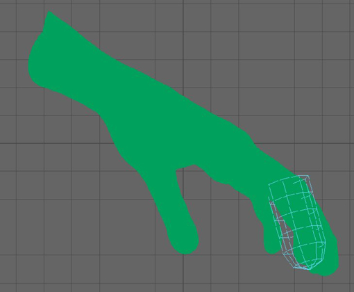
Figure 4.38 Delete the top section of the cylinder.

Figure 4.39 Use the Move tool to force the surface to snap to the hand.

Figure 4.40 Shape four more cylinders for the other fingers.
To see a version of the scene to this point, open the hand_v02.ma scene from the chapter4scenes directory at the book’s web page.
Quad Draw
Quad Draw allows you to generate polygon faces rapidly that can conform to another surface. The following procedure uses Quad Draw to retopologize a high-resolution zombie hand:
- Continue with the scene from the previous section, or open the
hand_v02.mascene from thechapter4scenesdirectory at the book’s web page. - Select the fingers and choose Mesh ➣ Combine.
- Delete the history of the finger geometry.
- Select the hand and make it a live surface.
- Select the fingers and open the Modeling Toolkit. Choose Quad Draw from the Tools rollout. The wireframe of the finger geometry turns black (see Figure 4.41).
-
The finger geometry may not be evenly spaced on the live surface. Quad Draw has a Relax feature built into the tool. Hold Shift and LMB-drag on the index finger to relax the geometry. Hold
band LMB-drag left or right to change the size of the area of influence for the Relax operation.Quad Draw has its own marking menu. You can access it by holding Ctrl+Shift, or Cmd+Shift on a Mac, and RMB-clicking. Options on the marking menu allow you to force the Relax operation to be applied to interior vertices, border vertices, or both. By default, Relax is set to Auto Lock. Auto Lock uses the type of vertex you click on first, interior or border, to determine what the Relax operation will affect.
- Relax the border vertices and interior vertices for all the fingers.
- Hold Ctrl+Shift and RMB-click over the index finger geometry. Choose Extend: Loop from the marking menu.
- Hold Tab and LMB-click to extend the edge loop up the length of the finger. Add two extensions to complete the finger length.
- Repeat the process of extending the finger geometry for each of the fingers (see Figure 4.42).
- You want to connect the thumb and index finger together. The flow of the geometry on the end of the thumb may be going in the wrong direction. MMB-drag a component, vertex, or edge to slide it into the proper position. Use Figure 4.43 as a guide.
- Hold Shift and hover over the empty space between the thumb and index finger. A green polygon fills in the area. Depending on the position of your mouse, you may need to move around a little to get the proper quad. LMB-click to create the face. Add another face directly above (see Figure 4.44).
- Ctrl+click to insert an edge loop. Add a total of three edge loops (see Figure 4.45). You can hide the live surface hand at this point if it becomes distracting.
- Holding Shift, fill in the polygons between each of the fingers.
- Using Tab, extend the top loop of the index finger. While extending the loop, drag the selection toward the faces that you added in step 13. The corner vertex will automatically weld when it comes close to another vertex (see Figure 4.46).
- Quad Draw also allows you to move components without having to select them. Moving the mouse over the geometry displays the preselection highlight. LMB-drag to move the component when it is highlighted. Shift the new vertices toward the interior of the hand to make the faces evenly spaced (see Figure 4.47).
- Extend the fingers and the geometry in between each finger by one face loop. If the geometry does not automatically weld while extending a loop, you can LMB-drag the component to its desired location. When the components get close enough, they will automatically weld.
-
At this point, you can extend the entire edge loop that wraps around the hand. Extend the loop three times to match the geometry to the geometry of the thumb (see Figure 4.48).
While you are extending the loops, be sure to check that the new vertices are not welding to any unwanted locations. If you continue to drag the loop, the weld will break. After each extension, you may want to use the Relax operation to keep the geometry uniformly spaced.
- You can continue to extend loops to complete the hand retopology or use another technique available with Quad Draw. LMB-click the live surface hand where you want to place a vertex. A green dot will appear (see Figure 4.49).
- Add several more green dots. Keep in mind that you are creating vertices and that you want them to be in alignment with your existing geometry.
- You can now hold Shift and LMB-drag over the empty space between the dots and geometry to draw new faces (see Figure 4.50). You can press and hold Ctrl+Shift and LMB-click to delete components.
- Save the scene as
hand_v03.ma.

Figure 4.41 With the finger geometry selected, choose Quad Draw from the Modeling Toolkit.

Figure 4.42 Extend the edge loops on each of the fingers.

Figure 4.43 Shift the surface flow of the thumb to align with the index finger.

Figure 4.44 Hold Shift to generate quads between existing faces.

Figure 4.45 Insert three edge loops between the thumb and index finger.

Figure 4.46 Drag a new loop from the index finger.

Figure 4.47 Make the edges of the new geometry evenly spaced.

Figure 4.48 Extend the geometry from the fingers three times.

Figure 4.49 Click to create a green dot where you want a new vertex.

Figure 4.50 Drag in the empty space to draw new faces.
To see a version of the scene to this point, open the hand_v03.ma scene from the chapter4scenes directory at the book’s web page.
Reduce
The Reduce tool can remove unneeded vertices without affecting an object’s general shape. Specific controls allow you to keep borders, hard edges, or creases. The following steps take you through the process of reducing a polygon mesh:
- Open the
reduce1.mascene from thechapter4scenesfolder at the book’s web page. - Select the hand and choose Mesh ➣ Reduce ➣ ❒.
- Select Keep Original and click Apply.
- A duplicate hand is created. Click the Wireframe On Shaded icon in the viewport.
- Select either glove and open its Attribute Editor. Click the polyReduce1 tab.
- Make sure Reduction Method is set to Percentage and change the percentage to
93.0. The model is reduced quickly and efficiently (see Figure 4.51).

Figure 4.51 The polygons for the model on the left have been reduced.
You can change Reduction Method to Vertex Limit or Triangle Limit, and the values will automatically adjust without affecting the reduced surface. To see a version of the reduced glove, open the reduce2.ma scene from the chapter4scenes directory at the book’s web page.
The Bottom Line
Implement box modeling. Box modeling allows you to start with a simple primitive that you can extrude to create a complex form.
Master It Starting from a smoothed cube, use box-modeling techniques to create a head.
Employ build-out modeling. From a single polygon, you can extrude edges to create smaller sections of a larger object.
Master It Use the build-out method to model an ear.
Sculpt polygons. The sculpting tools allow you to shape your geometry as if it were clay.
Master It Use the sculpting tools to shape muscle definition into the female model.
Use retopology tools. Highly detailed, sculpted models are impractical to take through the production pipeline. Instead, the high-resolution model is retopologized to a lower, more manageable resolution.
Master It Use Quad Draw to create a low-polygon game model of the hand in
hand_v01.ma.