
Chapter 5
Rigging and Muscle Systems
Rigging is the process of creating an organized system of deformers, expressions, and controls applied to an object so that it can be easily and efficiently animated. A good rig should intuitively allow an animator to concentrate on the art of animation without the technical aspects of rigging getting in the way. In addition, a good rig should be well organized so that it can easily be changed, repurposed, or fixed if there is a problem.
Rigging as a practice is continually evolving in the industry. New technologies, concepts, and approaches emerge every day and are widely discussed and debated among professional technical directors throughout the world. Although this chapter offers advice on how best to approach creating part of a character rig in the Autodesk® Maya® program, its main purpose is to help you understand how the tools work so that you can approach creating your own rigs and adapting rigging practices from others.
The first part of this chapter explores techniques for creating efficient character rigs. There are many approaches to rigging characters; the main focus of these exercises is to build an understanding of how the Maya toolset works so that you can adapt it to your preferred rigging workflow. We provide additional tips and tricks that can help you avoid common rigging pitfalls.
The second portion of the chapter is devoted to Maya Muscle, a plug-in designed to create realistic deformations for character rigs. The muscle system works with skeletons to simulate the qualities of flesh and skin.
The focus of this chapter is to rig and weight a giraffe. You will create controls to operate its legs and spine. Regardless of the character—in this case a giraffe—the concepts are the same. The typical pipeline is to build a skeleton, create the rig, and then weight the geometry.
In this chapter, you will learn to
- Create and organize joint hierarchies
- Use Human Inverse Kinematics rigs
- Apply skin geometry
- Use Maya Muscle
Understanding Rigging
![]()
Today’s characters are more complex than ever. Even the simplest are expected to have a full range of motion and perform as if they actually existed. To achieve this level of realism, numerous tools and techniques are applied. In this chapter, you’ll build a realistic giraffe.
The most common types of rigs are created using joint deformers. In character animation, a skeletal system is created from joints to match the basic shape of the character. A simple wireframe sphere represents a joint. Joints are connected by bones, which are represented by a wireframe pyramid. When one joint is parented to another joint, the bone is aligned so that the pointed end of the pyramid points to the child joint (see Figure 5.1).

Figure 5.1 Joints are positioned based on the shape of the object they are meant to deform.
The geometry of the character is bound or skinned to the joints so that the joints deform the geometry—making knees bend, wrists twist, fingers clench, and so on. Each joint in a hierarchy exerts influence over each vertex of the geometry, pushing or pulling it in one direction or another. The amount of influence exerted on a vertex by a joint is controlled through weighting.
Once geometry has been skinned to a skeleton of joints, a system of controls is created to make animating the joints as simple as possible. Controls can be created from locators or curves or any other node that can be selected in the viewport. These nodes then control the movement of joints via expressions, utility nodes, constraints, or driven keys. You used a simple control system in Chapter 2, “Introduction to Animation,” to rig a mechanical bug model.
In addition, other types of deformers are often applied to the geometry to compensate for the shortcomings of simple joint deformations. Influence objects, lattice deformers, Maya Muscle, and other tools and techniques are often used to create believable motion and to simulate the properties of flesh and tissue for characters.
Creating and Organizing Joint Hierarchies
The Create Joints tool creates a joint each time you click the scene. As long as the Create Joints tool is active, each time you click the scene, a new joint is added and parented to the previous joint, forming a simple hierarchy known as a joint chain. To exit the Create Joints tool, press the Enter key on the keyboard. This is useful if you need to finish one joint chain and then start another.
You can create branches of joints by parenting joint chains to intermediate joints in the initial chain. Parenting the branches and groups of joint chains lets you quickly create sophisticated joint hierarchies known as skeletons.
Because many skeletons can become quite complex, they should be properly organized and named so that animators and other riggers (referred to as technical directors in some instances) can easily access and understand the skeleton and all of its various parts.
The orientation of joints relative to their parent joints must be consistent throughout the skeleton to achieve proper functionality. The default orientation of a joint, established when the joint is added to a chain, is often incorrect and can lead to problems such as gimbal lock.
Skeletons are built by using the Create Joints tool. The goal is to create joints to mimic the functionality of a real skeleton. It is not always necessary to replicate every single bone in your character. Often, you can create the same effect of the real thing through a reduced number of joints. Some other cases require the addition of joints that don’t exist at all to achieve the effect you are after. Either way, it’s important to remember that the goal of a skeleton is to provide the necessary structure for a character to move—in other words, to provide whatever it takes in the most efficient manner possible.
- Open the
giraffe_v01.mascene from thechapter5scenesfolder at the book’s web page (www.sybex.com/go/masteringmaya2016). The scene contains a polygon giraffe. -
Switch to the side view. The first part of the skeleton to draw is the giraffe’s front leg.
-
Switch to the Rigging menu set, and choose Skeleton ➢ Create Joints.
- Click the Snap To Projected Center icon, located to the right of Snap To Point in the Status Line. This new feature snaps any object to the relative center of a geometric object. In this case, it is being used to center the joints within the giraffe’s leg.
- To keep the joints visible through the geometry, choose Shading ➢ X-Ray Joints from the viewport’s menu.
-
Starting just below the neck, begin drawing five joints down the length of the leg. You can reposition the joints as you go. If you hold the LMB, instead of clicking you can move the joint to position it better. After you release the button, use the MMB to make other alterations. Continue clicking with the LMB until all five joints are drawn. When you’ve finished, press Enter to complete the operation. Use Figure 5.2 as a reference.
It’s important to have a slight rotation for the knee if you decide to use inverse kinematics later. (Inverse kinematics is a special type of control mechanism for animating the joints; this topic will be discussed later in the chapter.)
When you create inverse kinematics, Maya needs a hint as to how you want the joint to bend when the IK Handle is moved. For now, make sure that there is an angle in the joint chain at the location of the knee (joint3).
-
Using the down-arrow key, pick-walk through the skeleton’s hierarchy to reposition the rest of the joints. This method of moving the joints works fine as long as you move the joints in order.
If you go back up the hierarchy, any changes made to a joint affect all of the joints underneath it. To avoid this, with a joint selected, press Insert or Home on the keyboard to activate the joint’s pivot point. You can now move the joint independently.
Holding the
dkey also activates the joint’s pivot point. Figure 5.3 shows the joint’s final position in the front view. - Repeat the procedure for the left hind leg. You can use the Create Joints marking menu to make adjustments to your joint settings if needed by pressing RMB over a joint. Use Figure 5.4 for reference.
- Next is the giraffe’s spine. Switch to the side view.
-
You want the spine joints to be evenly spaced. This ensures that the geometry receives an even distribution of influence from the joints. Move off into empty space, and snap nine joints to the grid.
- Translate the root of the snapped joints just above the giraffe’s tail. The spine is much longer than the giraffe’s geometry.
- To maintain its uniform size, Shift+click each joint, starting with the tip and ending with the root.
- Select the Scale tool. The manipulator is displayed at the location of the last joint selected.
- Scale the skeleton in the z-axis until the tip is above the front leg’s second joint.
- Rotate each joint to get the proper curve in the spine. Use Figure 5.5 as a guide.
- The joints for the neck and tail are created in a similar fashion. Repeat the procedure, placing 11 joints in the tail and 8 in the neck. Figure 5.6 shows the finished skeleton parts.
- The only remaining joints are in the head. Choose Skeleton ➢ Create Joints.
- With Create Joints active, click the last neck joint.
- Click the end of the head. The head joint is automatically connected to the neck.
- Finish up the head by adding ears (see Figure 5.7).
- It’s now time to attach the front leg to the spine. You need to add one more joint, which would be the equivalent of the human clavicle, in between the spine and front leg. Create and position a single joint above the left leg, equal in height to the spine. Position it using Figure 5.8 as a guide.
- Select the root of the left leg. Hold Shift, and choose the newly created clavicle joint.
- Press the
pkey to parent the joints. - Select the clavicle joint, and parent it to the second-to-last spine joint.
- Repeat steps 18–21 for the hind leg. Instead of a clavicle, create a hipbone. Use Figure 5.9 as reference.
- Finish up by parenting the tail to the root of the spine.
- Save the scene as
giraffe_v02.ma.

Figure 5.2 Draw five joints for the giraffe’s front leg.

Figure 5.3 Move the joints in the front view.

Figure 5.4 Draw the bones for the left hind leg.

Figure 5.5 Rotate the joints to give curvature to the spine.

Figure 5.6 Create the neck and tail.

Figure 5.7 Finish the head by adding two more joints for the ears.

Figure 5.8 Create a clavicle joint.

Figure 5.9 Create a hip joint, and parent the joints together.
To see a version of the scene up to this point, open the giraffe_v02.ma scene from the chapter5scenes directory at the book’s web page.
Orienting Joints
By default, a joint’s rotation axis automatically adjusts so that the x-axis always points down the length of the bone to the next joint in the chain. This behavior can be turned off using the Move tool or by choosing Skin ➢ Move Skinned Joints. As with most nodes in Maya, you can also change the way a joint rotates. This is done for numerous reasons:
- To make sure that the orientation of the joint is aligned with its bone. (When you freeze the transforms on a joint, the joint orientation will match the joint’s parent and not the bone.)
- To help avoid gimbal lock.
- To change the orientation for effect or specific control. For instance, you can have the left leg rotate in unison with the right leg when both are rotated simultaneously. By altering the right leg’s orientation, you can have the legs rotate opposite one another in a scissor-like fashion when rotated simultaneously.
Typically, orientation is done prior to binding your geometry to the skeleton. This is to prevent your geometry from inheriting any transformations. However, Maya does provide tools, such as Move Skinned Joints, to orient joints after they have been attached to geometry.
Typically, each joint is oriented so that the x-axis of its rotation is aimed along the length of the joint. The axis points down toward the child joint.
![]()
- Continue with the scene from the previous section, or open the
giraffe_v02.mascene from thechapter5scenesdirectory at the book’s web page. - Select the skeleton’s root, and freeze transformations on Translate, Rotate, and Scale. You want to make sure that all of the joints have a rotation of 0 and a scale of 1. The translation cannot be zeroed, so it doesn’t matter if it is included in the operation.
- With the root still selected, open the options of the function Skeleton ➢ Orient Joint. By default, the Orient Joint function affects child joints when applied to a parent. Since you are starting at the root of the skeleton and working your way down, you can leave this option selected.
- Keep all of the default settings. The Toggle Local Axes Visibility button hides or makes visible the local axes for any selected joint, and it is useful for checking the accuracy of your joint’s orientation without you having to leave the tool.
-
Choose Orient; Figure 5.10 shows the resulting Orient Joint options.
The rotation axis of each joint should be consistent throughout the skeleton to ensure predictable behavior. Ideally, the red x-axis should be pointing down the length of the joint, and the rotation of the green y-axis and the blue z-axis should match throughout the skeleton as much as possible. There will be exceptions to this based on the requirements of the skeleton or your own personal preference. In general, consistency is the most important aspect to watch out for.
- Check all of the joints for consistency. Some of the joints may not have oriented properly based on their position in the world. If that’s the case, reorient the joint by deselecting Orient Children Of Selected Joints in the Orient Joint options. Toggle the joints’ local axes to double-check your work.
-
Save the scene as
giraffe_v03.ma.To see a version of the scene up to this point, open the
giraffe_v03.mascene from thechapter5scenesdirectory at the book’s web page.

Figure 5.10 Use the Orient Joint tool to force the x-axis down the length of the bone.
Naming Joints
When creating a skeleton, you need to be extremely conscientious about how you name the joints. Clear, concise naming helps everyone involved in the animation understand how the rig is set up and how each joint is supposed to function. When naming joints, use a prefix such as L_ to indicate the left side and R_ to indicate the right side. If a joint is to be used as a control, use a suffix such as _CTRL. The advantage of being consistent with prefixes and suffixes is that you can easily search and replace the prefix or suffix if it needs to be changed on a large number of joints.
- Continue with the scene from the previous section, or open the
giraffe_v03.mascene from thechapter5scenesfolder at the book’s web page. - Open the Outliner, and select each of the joints making up the spine, starting with the root joint. Use Figure 5.11 as a guide.
- Click the icon next to the input field on the Status Line.
- Choose Rename. Type
spineand press Enter. Maya changes the name and automatically increments the numbering. -
Rename the neck and tail the same way.
- Naming the legs is more of a manual process since each joint should be named differently. Starting from the top of the front leg, name the joints based on the sidebar “Quadruped Bone Names” (be sure to include the underscores).

-
To prevent the leg-joint names from having a conflict from left to right and to organize your naming structure better, add a prefix to all of the names. Select the root joint of both legs. Choose Modify ➢ Prefix Hierarchy Names. In the input field, enter
L_.It is also a good idea to add a suffix to the joints to prevent confusion further along in the rigging process.
- Select all joints to the legs.
- Choose Modify ➢ Search And Replace Names.
- In the Search For field, enter
_. - In the Replace With field, enter
_jnt. -
Click Replace.
The underscore you added to the names is swapped out with _jnt, and the names are now complete.
You could have easily typed
_jntas you were creating each of the names. The main point of the preceding step was to familiarize you with the Search And Replace tool. In addition, if you are renaming numerous nodes or are unsure of your naming convention, you can add an underscore to make altering the name of multiple objects easier.Refer back to Figure 5.11 to see the final hierarchy and names.
- Save the scene as
giraffe_v04.ma.

Figure 5.11 Name each of the joints to make its purpose clear and to keep it organized.
To see a version of the scene up to this point, open the giraffe_v04.ma scene from the chapter5scenes directory at the book’s web page.
Mirroring Joints
The Mirror Joint command is used to duplicate part of the skeleton across a specified axis. It’s identical to using Joint Symmetry during the creation of a joint but has the added advantages of renaming and grouping to an existing hierarchy. For example, if a joint chain is parented to part of the skeleton or the collarbone is connected to the spine, the mirrored joint chain is parented to the same joint in the spine.
- Continue with the scene from the previous section, or open the
giraffe_v04.mascene from thechapter5scenesdirectory at the book’s web page. - Select L_clavicle_jnt.
- Choose Skeleton ➢ Mirror Joint ➢ Options.
-
In the options, set Mirror Across Axis to YZ, and set Mirror Function to Behavior.
Behavior is usually the best option when building character skeletons. When this option is enabled, corresponding joints on either side of the central axis rotate the same way. So if both shoulder joints are selected and rotated, both arms will rotate forward toward the chest, producing a mirror image across the central axis. The Orientation option means that when corresponding joints are rotated the same amount on the same axis, one of the arms will have the opposite behavior of the other.
- In the Replacement Names For Duplicated Joints section, set Search For to
L_and Replace With toR_(see Figure 5.12). This automatically renames the joint chains based on what you put in these fields. In this case, the front leg on the giraffe’s right side will use the prefix R_. - Click the Apply button to mirror the leg.
- Repeat the process for the hind leg and the ear.
- Save the scene as
giraffe_v05.ma.

Figure 5.12 Duplicate joints are automatically renamed with the search and replace options.
To see a version of the scene up to this point, open the giraffe_v05.ma scene from the chapter5scenes directory at the book’s web page.
Rigging the Giraffe
As mentioned at the beginning of the chapter, today’s rigs must be robust. Many different tools and aspects of Maya come together when character rigging. Inverse kinematics (IK) was introduced in Chapter 2, where you created a simple mechanical bug using IK Handles and basic techniques. In this section, you’ll explore inverse kinematics a little further as well as some of the specialized IK rigging tools that Maya offers.
As discussed in Chapter 2, kinematics is the study of the motion of objects. There are two main types of kinematics:
Forward Kinematics This refers to a situation in which each joint in the chain inherits the motion of its parent joint.
Inverse Kinematics This causes the joints in a chain to orient themselves based on the position of a goal known as the end effector.
In this section, you’ll learn in more detail how to set up and use inverse kinematics.
IK Legs
![]()
Maya uses several types of solvers to calculate how the bones orient themselves based on the position of the end effector. In Chapter 2, you used the Single-Chain solver, which is a simple solver with a few controls.
- Open the
giraffe_v05.mascene from thechapter5scenesdirectory at the book’s web page. - From the Rigging menu set, choose Skeleton ➢ Create IK Handle ➢ Options.
- In the options, set Current Solver to Rotate-Plane Solver and leave the other settings at the defaults (see Figure 5.13).
-
With the Create IK Handle tool active, click L_upperarm_jnt, and then click L_forefoot_jnt. You’ll see a line drawn between the first joint you clicked and the second joint. The line is known as the IK Handle Vector. You can also see a line that runs through the joint chain (see Figure 5.14).
Inverse kinematics controls can be applied to any joints in the chain, not just between the root and the end joint.
In the Outliner, you’ll see that a node named effector1 has been added at the end of the chain. Also, a node named ikHandle1 appears in the Outliner.
-
Switch to the perspective view, select ikHandle1 in the Outliner, and move it around. Notice how the joint chain reacts. Notice also that in some positions, the joints flip around to try to match the position of the IK Handle.
In the Attribute Editor for ikHandle1, look in the IK Handle Attributes. The two main settings for the IK Handle are Snap Enable and Stickiness:
- When Snap Enable is on, the IK Handle snaps back to the end joint.
-
The Stickiness setting keeps the joints oriented toward the goal when the root joint is moved. This is useful for legs because it keeps the feet from sliding on the floor.
The difference is obvious:
- Move L_upperarm_jnt while Stickiness is set to Off.
- Use Undo to return the joint to its original position.
- Set the Stickiness setting to Sticky.
- In the Outliner, select L_shoulder_jnt and move the joint around; note how the chain remains oriented toward the IK Handle.
- Set Stickiness back to Off before continuing.

Figure 5.13 Choose Rotate-Plane Solver in the IK Handle Settings options.

Figure 5.14 Attach the IK Handle to the joint chain by clicking the two end joints in the chain. A line between the two selected joints indicates inverse kinematics.
To animate a joint chain with inverse kinematics, you set keyframes on the IK Handle, not the joints. In most situations, you’ll want to constrain the IK Handle to another type of control object, such as a curve. The control is keyframed, and the IK Handle is constrained to the control so that it inherits the animation of the control. Constraining the IK Handle to another node produces the same effect as the Stickiness option. Let’s add a simple control handle to the front leg.
An ideal animation rig should be easy to understand and animate. This means the controls should be clearly labeled and easy to select directly in the viewport window. With any handle, the animator should be able to enter 0 in all the translation channels for the controls to return the rig to the start position if needed. IK Handles use world space coordinates, so setting their translation channels to 0 moves a handle to the origin. One common solution to this problem is to constrain the handle to a locator, which can then be used to animate the handle. You can set a start position for the control and then freeze transformations on it so that when the translation channels are set to 0, the control moves to the start position and brings the IK Handle along.
-
Choose File ➢ Import. Import
sphereHandle.mafrom thechapter5scenesdirectory at the book’s web page.The imported sphere was created by duplicating the surface curves of a low-resolution NURBS sphere. The multiple curves were cut and reattached into a single continuous curve. When designing your own control handle, you can always overlap the curve onto itself. You will not notice a performance hit by using a few extra control vertices.
- Snap the sphere to the center of L_forefoot_jnt.
- Freeze the transforms, and rename it to
L_FrontLeg_CTRL. - With the sphere selected, Shift+click the IK Handle.
- Choose Constrain ➢ Point ➢ Options.
- Reset the tool settings from the Edit menu to make sure you are using the defaults. Add the constraint.
- Add a Single-Chain handle from L_forefoot_jnt to L_forefoottip_jnt. The Single-Chain handle functions differently, and it is not affected as the Rotate-Plane handles are when they are constrained.
- Turn on Stickiness to keep the handle fixed.
- Parent the Single-Chain handle to the sphere.
- Save the scene as
giraffe_v06.ma.
To see a version of the scene up to this point, open the giraffe_v06.ma scene from the chapter5scenes directory at the book’s web page.
FK Blending
Once the constraint is added, new joints appear over the leg. These joints are a representation of a forward kinematics chain. Maya automatically applies FK to any IK chain. Figure 5.15 shows a combination of joints.

Figure 5.15 The FK joints are drawn larger than the IK joints.
The FK joints are displayed larger than the IK joints to help differentiate between the two. You can control how both are displayed by choosing Windows ➢ Settings/Preferences ➢ Preferences and then selecting Kinematics in the Display category. Essentially the two joints are the same. They do not have separate nodes, but they can be controlled independently.
The IK Handle inherently has an IkBlend attribute. When it is set to 1, the IK solver is 100 percent active. When set to 0, FK is 100 percent active. It is possible to blend the effects of both by using any value in between. As with the IK Handle, you do not want to keyframe the FK joints directly. Instead, you can assign handles to each joint. Let’s do that next:
- Open the
giraffe_v06.mascene from thechapter5scenesdirectory at the book’s web page. - Choose Create ➢ NURBS Primitives ➢ Circle.
- Snap the circle to L_forearm_jnt.
- Scale the circle uniformly to
0.25. - Freeze the transforms, and delete the circle’s history.
- Change the name of the circle to
L_forearm_FK. - With the circle selected, Shift+click L_forearm_jnt.
- Choose Constrain ➢ Orient ➢ Options.
-
In the Orient options, select Maintain Offset. Make sure that all of the axes are constrained, and choose Add.
Rotating L_forearm_FK won’t do anything yet. To see the effects of the handle, set the IkBlend attribute to
0and then rotate the handle. After testing it, be sure to return the handle’s rotate values to0. - Duplicate L_forearm_FK, and rename it to
L_upperarm_FK. - With L_upperarm_FK selected, Shift+click L_upperarm_jnt.
-
Choose Constrain ➢ Orient using the same options from step 9 (see Figure 5.16).
When you rotate L_upperarm_FK with IkBlend set to 0, you will notice that L_forearm_FK is left behind. A point constraint will fix this.
- Select L_forearm_jnt.
- Shift+click L_forearm_FK.
- Choose Constrain ➢ Point ➢ Options. Make sure that the options are set to their default, and click Add.
- Save the scene as
giraffe_v07.ma.

Figure 5.16 Use primitive NURBS circles for FK Handles.
To see a version of the scene up to this point, open the giraffe_v07.ma scene from the chapter5scenes directory at the book’s web page.
Rotate-Plane Solver
![]()
The Rotate-Plane solver (RP solver) differs from the Single-Chain solver in that the end effector matches the position of the IK Handle but not the rotation. Instead, the rotation of the chain is controlled using a special disc-shaped manipulator that can be keyframed if needed. The RP solver is more predictable and used most often, especially when creating skeletons for characters. The RP solver is similar to the SC solver except that an additional circular icon appears, indicating the pole vector for the chain. The pole vector determines the direction of rotation for the joints as they attempt to reach the IK Handle (see Figure 5.17).

Figure 5.17 The RP solver adds an additional control to determine how the chain rotates as it attempts to match the position of the IK Handle.
You can select the IK Handle (ikHandle2 in the example) and turn on the Show Manipulators tool. Using this tool, you can do the following:
- Rotate the blue disc to adjust the rotation of the chain
- Change the numeric values in the Channel Box using the Twist channel
The pole vector of the chain is indicated by the white triangle in the rotate plane indicator at the start point of the IK chain. Changing the pole vector also changes the orientation of the chain. The pole vector determines the angle of the rotate plane for the RP solver. This can be used to control unwanted flipping while animating the IK Handle.
The Twist attribute is directly related to the pole vector. In general, you’ll want to adjust the pole vector to orient the chain properly and then use the Twist attribute to solve any flipping problems you may encounter while animating.
The pole vector of an IK Handle can be constrained to another node, just like the IK Handle. Controlling the pole vector through a separate node allows you to zero out the transforms and gives you a visual representation in the viewport. Let’s add one to the front leg:
- Open the
giraffe_v07.mascene from thechapter5scenesdirectory at the book’s web page. - The pole vector can be controlled just like the IK Handle. Choose File ➢ Import, and select
poleVectorHandle.mafrom thechapter5scenesdirectory at the book’s web page. Rename the imported handle toL_Leg_PV. - With point snapping on, move L_Leg_PV on top of L_upperarm_jnt. Turn off point snapping.
- Select L_Leg_PV and choose Modify ➢ Freeze Transformations. This will zero out the channels in the Translate XYZ.
- Open the IK Handle’s Attribute Editor.
- Choose Copy Tab at the bottom of the window.
- From the copied window, open the IK Solver Attributes and find the Pole Vector XYZ coordinates (see Figure 5.18).
-
Copy the Pole Vector’s XYZ coordinates to the L_Leg_PV Translate XYZ. The values of the pole vector place the handle along the same vector. This prevents the pole vector from shifting or being altered from its vector when it will eventually be constrained to the handle.
By adding an Aim constraint, you force the pole vector handle always to orient in the same direction of the forearm joint. This does not provide any necessary functionality—only a better visual representation.
- Select L_forearm_jnt.
- Shift+click L_Leg_PV. Choose Constrain ➢ Aim ➢ Options.
-
Change the options to match those in Figure 5.19, and click Add.
The pole vector handle is too close to the joints. This will cause the joint chain to flip a lot when the IK Handle is moved around.
- Select L_FrontLeg_PV, and translate it in the Z to about 4.0 units.
- Find L_FrontLeg_PV in the Outliner or Hypergraph.
- Attached to it is the Aim constraint. Select and delete it.
- Select L_FrontLeg_PV, and freeze the transforms.
- With L_FrontLeg_PV still selected, choose the leg’s IK Handle.
- Add a pole vector constraint by choosing Constrain ➢ Pole Vector. You can see the connection, as shown in Figure 5.20, if you select the IK Handle.
- Save the scene as
giraffe_v08.ma.

Figure 5.18 Find the Pole Vector attributes in the Attribute Editor.

Figure 5.19 Set the Aim constraint options.

Figure 5.20 Use a pole vector constraint to control the pole vector of the front leg’s IK Handle.
To see a version of the scene up to this point, open the giraffe_v08.ma scene from the chapter5scenes directory at the book’s web page.
Creating Custom Attributes
![]()
You have added several control handles to the leg. The IK and FK Handles have overlapping functionality. When the leg is under full control of the IK, there is no need to see the FK controls; likewise, when the FK is in full control, there is no need to see the IK controls. You can add an attribute that will toggle between the two without any direct input from the user. Using utility nodes and custom attributes can add a tremendous amount of flexibility and power to your rig. The next exercise creates a custom attribute and, based on its value, turns off or on the visibility of your controls:
- Open the
giraffe_v08.mascene from thechapter5scenesdirectory at the book’s web page. The scene picks up where the previous exercise left off. - Select L_FrontLeg_CTRL.
- Choose Modify ➢ Add Attribute. The Add Attribute window is displayed. Type IkBlend for the Long Name and change the settings to match those in Figure 5.21. Make sure that the Make Attribute option is set to Keyable and that the Data Type option is set to Float.
-
Click OK to add the attribute.
You can also access the Add Attribute window through the Channel Box by choosing Edit ➢ Add Attribute.
- Look in the Channel Box with L_FrontLeg_CTRL selected, and you’ll see the new channel named IkBlend. The attribute exists but has no functionality.
- Select L_FrontLeg_CTRL and L_Forearm_FK, and choose Windows ➢ Hypergraph: Connections (see Figure 5.22).
- In the Hypergraph window, choose Rendering ➢ Create Render Node.
- With the Create Render Node window open, choose Utilities from the Create Bar panel on the left.
-
Select Condition from the right panel. A condition node is created in the Hypergraph.
A condition node sets up an
if…elsestatement. In this exercise, you want the condition to state that if IkBlend is 1, then the visibility of the FK Handles is off. Furthermore, if IkBlend is less than 1, the FK Handles visibility is on. - MMB-click L_FrontLeg_CTRL, and drag it onto Condition1. Notice that when you drag the mouse, a plus sign is displayed. This lets you know you are performing an action.
- After you release the MMB, choose Other from the pop-up menu. The Connection Editor opens with the first and second nodes preloaded (see Figure 5.23).
- Choose IkBlend from the bottom of the left-side list (L_FrontLeg_CTRL).
- In the right-side list (Condition1), select firstTerm. The two attributes are now connected, with IkBlend driving the values of the firstTerm attribute. Leave the Connection Editor open.
- Open condition1’s Attribute Editor. Use Figure 5.24 for the rest of the settings.
- The First Term setting is the variable; its value determines if and what action needs to be taken.
- The Second Term setting is what the First Term is compared against.
- Operation specifies how the comparison should be executed.
-
True and False are what should happen based on the condition. In this case, if the condition is true and IkBlend is less than 1, the resulting value will be 1. If it is greater than 1, or false, the resulting value will be 0.
You need only one channel to make this operation work. Use the first attribute, which is defined as Color Red. The other two channels, blue and green, have been set to 0 simply to avoid confusion.
- With Condition1 selected, choose Reload Left in the Connection Editor.
- Select L_forearm_FK, and choose Reload Right.
-
Select OutColorR from Condition1 and Visibility from L_forearm_FK.
The connection is complete. You can test it by opening L_FrontLeg_CTRL in the Channel Box and setting the IkBlend attribute to anything less than 1.
- Connect the same OutColorR of Condition1 to the visibility of L_upperarm_FK. Now they both turn on or off simultaneously. Figure 5.25 shows the connected nodes in the Hypergraph.
- Save the scene as
giraffe_v09.ma.

Figure 5.21 Add an attribute called IkBlend to L_FrontLeg_CTRL.

Figure 5.22 The node’s up- and downstream connections are displayed in the Hypergraph.

Figure 5.23 The Connection Editor shows attributes of the two nodes to be connected.

Figure 5.24 Change the values of the Condition node.

Figure 5.25 The connections are displayed in the Hypergraph.
To see a version of the scene up to this point, open the giraffe_v09.ma scene from the chapter5scenes directory at the book’s web page.
Spline IK
The IK Spline solver uses a curve to control the rotation of the joints. This is ideal for long snaking chains and tails. The solver can generate a curve or use an existing curve. The CVs of the curve become the manipulators for the joint chain. Usually, it’s a good idea to create clusters for the CVs of the curve and animate CVs of the curve indirectly using the clusters. In the next example, you’ll use a spline IK to control the giraffe’s spine:
- Open the
giraffe_v10.mascene from thechapter5scenesdirectory at the book’s web page. The scene has been continued from the previous exercise; all of the legs have been rigged. - Choose Skeleton ➢ Create IK Spline Handle ➢ Options.
- Select Auto Create Curve, and deselect Auto Simplify Curve to prevent Maya from reducing the number of control vertices in the spline. Use Figure 5.26 to confirm your settings.
- With the IK Spline Handle tool active, choose root_jnt and then spine8_jnt. The tool autocompletes and connects the spine chain to a curve. If you grab a CV and move it, you can see the spine’s motion, as Figure 5.27 demonstrates.
-
Select the curve and choose Select ➢ Cluster Curve. Doing so automatically places clusters on each CV of the curve (see Figure 5.28). When animating the curve, you should keyframe the clusters and not the CVs of the curve. For more information on clusters, consult Chapter 6, “Animation Techniques.”
The cluster handles are created with their translates and rotates set to 0, which is perfect for animating. However, cluster handles have a low selection priority, making them difficult to deal with, especially in a complex rig. As with the other handles, it is best to create a custom controller to operate the clusters.
- Choose Create ➢ NURBS Primitive ➢ Circle.
- Rename the handle to
shoulder_CTRL, and snap it to spine7_jnt. - Scale the handle uniformly to 0.7.
- Duplicate shoulder_CTRL, and rename it to
torso_CTRL. - Translate torso_CTRL to be centered between spine5_jnt and spine4_jnt. Scale it uniformly to 0.5.
- Duplicate torso_CTRL, and rename it to
hip_CTRL. -
Snap hip_CTRL to spine1_jnt. Figure 5.29 shows the position of the three circles.
The cluster handles will not react through a parent-child relationship because the Relative feature is selected. In addition, parenting the cluster handles and getting them to move with the character results in unwanted deformations and double transformations on the spline curve. Instead, the cluster handles are constrained to the NURBS curves.
- Select hip_CTRL, and Shift+click cluster1Handle.
- Choose Constrain ➢ Parent ➢ Options.
- Select Maintain Offset, and make sure that All is selected for Translate and Rotate. Figure 5.30 shows the settings. Repeat this step for the next three cluster handles.
- Select torso_CTRL, and add the same Parent constraint from step 16 to clusterHandle 5, 6, 7, and 8.
- Select shoulder_CTRL, and add the same Parent constraint from step 16 to clusterHandle 9, 10, and 11.
-
Grab hip_CTRL, and move it around. Notice how joints pull away from the curve and the other control handles. Figure 5.31 shows an example of this.
This is undesirable and causes major problems while animating. The fix is to point-constrain each control to the one before it. However, constraining a handle directly would lock out the translation and prevent you from keyframing it. Empty group nodes are used instead, and the control handles are parented to them.
- Choose Create ➢ Empty Group or Ctrl/Cmd+g. null1 is created. Change its name to
torso_GRP. - Snap torso_GRP to spine4_jnt. Freeze the transforms.
- Select hip_CTRL and then torso_GRP.
- Choose Constrain ➢ Point ➢ Options.
- Check Maintain Offset, and make sure that all axes are being constrained. Click Apply.
- Select torso_CTRL, and make it a child of torso_GRP.
- Choose Create ➢ Empty Group.
- Change the null’s name to
shoulder_GRP. - Snap shoulder_GRP to spine7_jnt. Freeze the transforms.
- Select torso_CTRL and then shoulder_GRP.
- Choose Constrain ➢ Point ➢ Options.
- Select Maintain Offset, and make sure that all axes are being constrained. Click Apply.
- Move the hip_CTRL again and look at the differences the groups and constraints have made. Figure 5.32 shows the results of these actions.
- Save the scene as
giraffe_v11.ma.

Figure 5.26 Create an IK Spline Handle with these options.

Figure 5.27 The CVs of the spline are used to manipulate the spine’s joints.

Figure 5.28 Each CV of the spline is now attached to a cluster handle.

Figure 5.29 Position three NURBS circles along the giraffe’s spine.

Figure 5.30 Add a Parent constraint to the first four cluster handles.

Figure 5.31 The joints pull away from the curve, causing undesirable effects.

Figure 5.32 Shoulder and torso controls follow along with the hip control.
To see a version of the scene up to this point, open the giraffe_v11.ma scene from the chapter5scenes directory at the book’s web page.
IK Spline Handles come with an extra feature called Twist. Although this attribute shows up on other types of IK Handles, it affects only the spline IK. Ultimately, the giraffe’s final rig will not have any IK Handles visible, since control for all of them is being passed to a custom handle. Keeping in line with this, you can add the twist of the spline IK to a custom attribute on the shoulder control.
You can apply what you have learned to complete the rest of the giraffe. If you get stuck, take a look at the complete giraffe in the scene giraffe_v12.ma in the chapter5scenes directory at the book’s web page.
Human Inverse Kinematics
Human Inverse Kinematics (HIK) is used for full-body inverse kinematics. This system creates IK Handles that control an entire biped or quadruped skeleton rather than using multiple IK chains on individual limbs. It is a powerful system capable of producing smooth animations quickly. In addition, the time it takes to set up a full-body IK skeleton is a fraction of the time needed to create your own rig. HIK is a plug-in, but it is loaded automatically by default.
Perhaps the greatest strength of the HIK system is its ability to retarget animations from one character to another. Characters of different sizes and proportions can swap motions. Animation layers can be used to create nondestructive offsets to fix any discrepancies between the characters’ movements.
Skeleton Generator
The HIK tools allow you to create a custom skeleton and rig or use the system’s Skeleton Generator. Bipedal or quadrupedal characters can be created, but all must be in a T-pose or T-stance looking toward the positive z-axis. The HIK system also requires a standard set of 15 bones. The following example takes you through the steps to create a bipedal character:
-
Start with a new scene in Maya. From the Rigging menu set, choose Skeleton ➢ HumanIK. The Character Controls panel opens.
The Character Controls panel contains the Character Controls menu button (top-left corner) and the Start pane, which is divided into three sections: Create, Define, and Import. Clicking the Character Controls button reveals the full set of options available for the Character Controls.
-
Choose Create ➢ Skeleton from the Character Controls button or from the first section of the Character Controls panel. A large biped skeleton is created in the viewport, and the Character Controls panel is refreshed with a new set of options.
Figure 5.33 shows the skeleton created with the HIK Skeleton Generator.
-
In the Skeleton tab of the Character Controls panel, check Lower–Arms to add roll bones to the character’s forearms.
You can customize the existing skeleton further by adding or taking away toes, spine joints, and numerous other bones. You can also modify the bones directly to fit your character by translating and rotating the bones in the viewport.
After the skeleton is made, it must be characterized by the HIK system; characterizing a skeleton means mapping each joint to a corresponding joint within the HIK system. Once that’s done, the HIK solver can understand your skeleton and you can apply a control rig. Since you used the built-in Skeleton Generator, you do not need to map the bones.
- With any bone selected, click the Character Controls menu button and choose Create ➢ Control Rig. This automatically locks the skeleton from further changes. The Character Controls panel is updated again and a Control Rig is added to the skeleton (see Figure 5.34). Save the scene as
hikCharacter_v01.ma.

Figure 5.33 A skeleton generated by the HIK Skeleton Generator
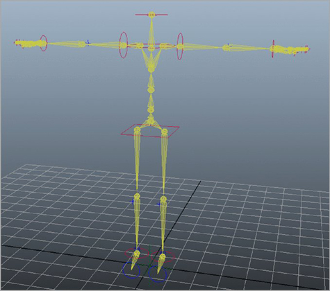
Figure 5.34 The Control Rig is added to the skeleton.
To see a version of the scene up to this point, open the hikCharacter_v01.ma scene from the chapter5scenes directory at the book’s web page.
Character Controls
The HIK system comes with a Character Controls panel (see Figure 5.35) that allows you to select the control handles of your character quickly and easily and to toggle among FK, IK, and full body IK. You can also click the encircled arrows to see exploded views of the hands and feet.

Figure 5.35 The Character Controls panel
Within the Character Controls panel is a row of icons located above the Skeleton, Definition, and Controls tabs. The first two icons allow you to toggle the visibility of the FK handles and bones. The next icon toggles the visibility of the full body skeleton. By default, this is turned off. Go ahead and choose the Show/Hide Skeleton icon to display the full-body skeleton. Since it appears under the FK bones, click the Show/Hide FK icon to turn the FK bones off.
The next three icons—Full Body, Body Part, and Selection—control the functionality of the control handles on the character. Starting in reverse order, the Selection icon allows you to move a handle without having the bones follow along. The next, Body Part, treats the bones connected to the selected handle as an ordinary IK system. Choose this icon, and select the left wrist handle. You can select the wrist handle through a viewport or from the humanoid image within the Character Controls panel. Use the Move tool to see how it affects the skeleton. Use Undo to return the skeleton to its default position. Now select the Full Body icon, and move the wrist handle again. Notice the difference (see Figure 5.36).

Figure 5.36 The left wrist handle is translated with Full Body IK turned on.
Whether you animate a body part or the full body, the effectors will always appear synchronized by default in the viewport. The effectors’ position is the final solved animation. You can turn the synchronization off or on by clicking the Character Controls menu button and choosing Edit ➢ Controls ➢ Align Control Rig.
The HIK system also has separate control over roll-bone behavior. If you added roll bones, you can alter the way rotation is distributed to them. The following steps take you through the process:
- Load
hikCharacter_v01.mascene from thechapter5scenesdirectory at the book’s web page. Select Character1_Ctrl_LeftWristEffector, and open its Attribute Editor. - In the Attribute Editor, choose the HIKproperties1 tab. Open the Roll & Pitch rollout.
- Set the Left Forearm Roll to
0.5. With a 0.5 value, the left forearm joint will rotate approximately half the amount of the left wrist effector’s rotation. - Set the Left Elbow Roll to
0.2. With a 0.2 value, the elbow joint will rotate approximately 20 percent of the left wrist effector’s rotation. This will also cause the left forearm to rotate 20 percent less than what was stated in step 3. - Rotate the left wrist effector in the x-axis. Select each joint along the forearm to see how the roll attributes affected their values.
At any time, you can return your character or parts of your character to their stance pose by clicking the Character Control menu button and choosing Edit ➢ Controls ➢ Stance Pose. The selection mode, set in the Character Controls panel, dictates whether the full body is returned to the stance pose or whether only the selected body parts are returned.
You can customize the character interface by adding your own image or moving the location of the effectors within the interface. This is achieved by editing the XML configuration files located in the Program FilesAutodeskMaya2016
esourcesCharacterControls directory. In the same directory is a DefaultImages folder containing all of the images needed for the interface.
Interoperability
You can send Human IK characters to the Autodesk® MotionBuilder® software by choosing File ➢ Send To MotionBuilder. The One-Click plug-in included with Maya must be loaded and MotionBuilder must be installed on your computer in order for this menu to appear. This feature allows you to send new scenes or update individual elements to MotionBuilder. You can also establish a live connection and stream animation from MotionBuilder on to your character in Maya. Streaming animation can be done using an HIK rig or custom rig of your own design.
You can convert bipedal Character Animation Toolkit (CAT) rigs from the Autodesk® 3ds Max® software into FK representations on a human IK skeleton in Maya. You can make changes to the character in Maya and then send it back to 3ds Max as an updated CAT character. You can also choose to “bake” the animation of your HIK character for greater interoperability. (Baking is the process of transferring information from one source to another.) Click the Character Controls menu button in the Character Controls panel; you can choose to bake the animation to the skeleton or control rig. The baking options update automatically depending on your selection, enabling you to bake the full body, body part, custom rig, or live skeleton.
Skinning Geometry
Skinning geometry is the process in which geometry is bound to joints so that as the joints are rotated or translated, the geometry is deformed. The terms skinning and binding are interchangeable. There are two types of skinning: smooth binding and interactive skin binding (an extension of smooth binding).
Polygon and NURBS geometry can be bound to skeletons; however, polygon geometry often produces more predictable results. In this section, you will continue with the giraffe, which is polygon geometry.
When geometry is smooth-bound to a skeleton, each vertex of the geometry receives a certain amount of influence from the joints in the skeleton. The weight value of the joints determines the amount of influence each vertex receives from a joint. By default, the values are normalized, ranging from 0 to 1, where 0 is no influence and 1 is full (or 100 percent) influence. Weight values can be normalized in two different ways: Post (the default method) or Interactive. Post weights are calculated only when the bound mesh is deformed, preventing previously weighted vertices from being changed. Interactive normalization sets the weight value exactly as you enter it, forcing the weights always to total 1.0. When you bind geometry to a skeleton, the vertex weights are set automatically based on the options you specify in the Smooth Bind command. In most situations, the weights of the geometry require further editing after executing the Smooth Bind command.
When binding geometry to the skeleton, make sure that the rotations of the joints in the skeleton are all at 0. This means that if an IK Handle has been added to the skeleton, you should select and disable the handle (choose Skeleton ➢ Disable Selected IK Handles) and then set the joint-rotation channels to 0. Bind the skin to the joints and re-enable the IK Handle (choose Skeleton ➢ Enable Selected IK Handles).
The pose the skeleton is in when you bind the geometry is known as the bind pose. If at some point you need to detach and reattach the geometry to edit the geometry, you must be able to return to the bind pose easily. Do so by selecting the skeleton’s root joint and choosing Skin ➢ Go To Bind Pose.
Editing the skin weights is usually accomplished through three tools:
Interactive Skin Binding Tool First, this tool enables you to alter the area of influence rapidly by each joint.
Paint Skin Weights Next, you can refine your weights further with this tool. It employs the Artisan brush interface to set weights interactively.
Component Editor You can also edit the weight values directly for selected vertices using the Component Editor. The Component Editor gives you precise control over each vertex and the exact amount of weight it receives.
Editing skin weights can be a difficult and occasionally frustrating process. In the upcoming exercise, you’ll learn a few tips that can help make the process a little easier and faster.
Interactive/Smooth Binding
Maya automatically assigns skin weights to each vertex of the geometry as it is bound to the joints. There are options for assigning these weights based on the vertices’ proximity to the joints and the number of joints that can influence any particular vertex. Even so, after binding, you’ll need to edit the weights using the Paint Skin Weights tool. If the geometry is very dense—meaning that it has a lot of vertices—this process can take a while.
Interactive skin binding uses an adjustable volume to define smooth skin weights. The volumes can be moved and shaped to fit your character’s geometry, all the while giving you instant feedback on how the vertices are being influenced.
Weighting the Giraffe
You don’t use just one tool when weighting a character. Numerous tools and techniques are applied to achieve maximum performance. In this exercise, you will weight the giraffe with an interactive skin bind:
- Open the
giraffe_v11.mascene from thechapter5scenesdirectory at the book’s web page. The scene has a complete version of the giraffe’s rig. - Select root_jnt and the giraffe’s mesh.
-
Choose Skin ➢ Bind Skin ➢ Interactive Skin Bind Options.
Notice that you can choose to bind the entire joint hierarchy or just selected joints. In this example, you’ll bind the entire hierarchy.
Here are the relevant settings:
Bind Method The bind method determines how joints influence vertices, by either following the skeleton’s hierarchy or simply using whichever joint is the closest. The hierarchy of the giraffe is complete and calls for every bone to be weighted; however, for the tips, use Closest In Hierarchy.
Include Method The include method dictates which vertices are included in the initial volumes. Your options are Closest Volume and Minimum Weight. Choosing Minimum Weight opens an additional option to set the length of the volume. By default this is 0.25, causing each volume to be 25 percent longer than the bone to which it is attached. Most characters will have a different area of influence based on their location. For instance, the giraffe’s knee needs to have a smaller falloff compared to the torso. Choose Closest Volume.
You can use two types of volumes—a cylinder or a capsule:
- A cylinder will deliver a hard edge.
- The capsule is rounded at its ends, providing a smoother falloff.
Keep the capsule turned on.
Skinning Method The skinning method has the greatest impact on your bind. You can use Classic Linear, Dual Quaternion, or a blend of both.
- Classic Linear does not preserve volume and produces a visible shrinking of the geometry.
- Dual Quaternion provides the most suitable deformations for realistic characters. It preserves the volume of a mesh when a joint is twisted or rotated.
Take a look at Figure 5.37 to see the differences between the two.
The last two settings relate to how many influences a single vertex can have. It is important to remember that joints are not the only nodes that can be bound to geometry. Other geometry can also be used, and it is therefore considered an influence as well. Most weighted objects do not require more than four influences per vertex, which is the default. In addition, a lot of game engines have a hard limit of four influences on a single vertex. After binding, you can keep the influences locked to four by selecting Maintain Max Influences. This is particularly useful when weighting geometry for an environment outside of Maya, such as a game engine. Keep the default settings for the giraffe (see Figure 5.38).
-
Choose Bind Skin.
Keep in mind that all the weighting can be altered after the bind has been applied. These settings merely give you a place to start and typically require a lot of fine-tuning. Furthermore, you can change these settings through the skinCluster node that is attached to the bound geometry (see Figure 5.39).
The giraffe’s initial bind is established; now it’s time to fine-tune its weighting. Traditionally, modifying weighted geometry has been like feeling your way around in the dark. The Interactive Skin Bind tool not only sheds light on each and every vertex but does so with precision and ease of use. The Interactive Skin Bind tool allows you to massage the weights quickly to an acceptable level.
-
Start with the giraffe’s front legs to get used to the controls. Select L_upperarm_jnt. If it isn’t active already, choose Skin ➢ Edit Smooth Skin ➢ Interactive Skin Bind Tool. By default, two volumes are displayed. The only interactive one is the volume on the selected joint. The second volume is a reflection that is attached to R_upperarm_jnt. The reflection is displayed based on the Reflection tool settings and operates the same way as it does with the transformation tools (see Figure 5.40).
Each volume can be translated, rotated, and shaped. A heat-style color graph is used to illustrate the joint’s influence, with red being the highest amount of influence and blue being the least. A few color presets are provided along with the ability to change the color graph any way you would like.
The capsule’s manipulator is also color-coded. Red, green, and blue are used to represent the three axes, respectively. Depending on which part of the manipulator you grab, the shape of the capsule is altered. For the most part, each axis scales the selected ring uniformly.
- Use the LMB and grab the top, red horizontal ring.
- Resize it to decrease the amount of influence.
- Repeat this operation for the lower ring.
- In addition to changing the capsule’s shape, you can use the traditional Move And Rotate manipulator (scale is based on the volume) to fit the capsule better to the geometry. The manipulator is located in the center of the capsule. Looking at the front of the giraffe, translate and rotate the capsule for a better fit. Do the same for its profile. Figure 5.41 shows the adjusted capsule.
- Visible interactivity has been limited so far because the giraffe is in its original bind pose position. Translate the leg
1.0in the Z and0.5in the Y. - Select L_upperarm_jnt. Notice that the geometry in the middle of the bone appears to be sagging (see Figure 5.42). This is an indication that the geometry is not weighted to 1 at those particular vertices. However, the heat map shows full influence. Use the up arrow to go to the preceding joint, L_shoulder_jnt.
-
L_shoulder_jnt overlaps L_upperarm_jnt, causing the problem. Use the down arrow to return to L_shoulder_jnt.
Maya is displaying the non-normalized weight of the joint; therefore, the color displayed is red. What you are actually seeing is the combined weight value of both joints.
- In the tool settings for Interactive Skin Bind, find Display Weights. It is located above the color graph. Change it to Normalized. You can now see the true weight value of the joint.
- Use the up arrow to go back to L_shoulder_jnt.
- Modify the volume to fit its bone better. You can hold Shift while moving the red rings to scale the entire volume uniformly. If you hold Shift while adjusting the green or blue ring, the effects are local to that ring. Figure 5.43 shows the results of the new volume shape.
- Save the scene as
giraffe_v12.ma.

Figure 5.37 The Classic Linear skinning method is applied to the joints on the left, and Dual Quaternion is applied on the right.

Figure 5.38 Bind the giraffe geometry to its skeleton.

Figure 5.39 The skinCluster node holds all the settings from the initial binding options.

Figure 5.40 The interactive volumes are reflected by default.

Figure 5.41 Translate and rotate the capsule to encompass the leg geometry.

Figure 5.42 The geometry in the middle of the bone is sagging even though the volume shows the hottest influence.

Figure 5.43 Modifying L_shoulder_jnt’s volume fixes the upper arm (front leg).
To see a version of the scene up to this point, open the giraffe_v12.ma scene from the chapter5scenes directory at the book’s web page.
![]()
Geodesic Voxel Binding
Geodesic Voxel binding is a binding method that creates a voxel representation of your mesh. A voxel is a volumetric pixel (described in more detail in Chapter 15, “Fluid Simulation”). The distance from the joint or influence object is calculated through the volume to determine the falloff. As a result, Geodesic Voxel binding provides greater accuracy and smoother results. If you are binding multiple meshes, the voxelization treats them as a single volume.
Geodesic Voxel binding is superior to the other binding methods since it is based on the true volume of the object. Essentially, the skeleton is aware of the object’s shape, helping to prevent things like arms being weighted to legs and finger weights bleeding over into other fingers. The drawback, however, is that it takes considerably longer to perform the initial bind. Binding with Closest In Hierarchy happens almost instantaneously, whereas you might wait minutes for Geodesic Voxel binding to complete. Increasing the voxel resolution with a geodesic bind also increases the computation time. Characters with detailed skeletons will most likely require a higher resolution, but the default value of 256 is suitable for most situations.
In a side-by-side comparison of binding methods, the differences may not be readily apparent. Take a look at Figure 5.44. The hand was bound to its skeleton using the default binding values for each of the different binding methods. The Geodesic Voxel bind is on the left. Look at how smoothly the geometry deforms while retaining its original shape. The Closest In Hierarchy method averages the weighting, causing the deformations to soften the details of the model. You can observe this on the interior angle of the bent finger. Its closest competition is the Heat Map bind (right). With Heat Map binding, however, the geometry is pinching, almost to the point of interpenetration. In addition, Heat Map binding does not support all geometry types, such as nonmanifold geometry, and it can fail as a result.

Figure 5.44 The three different binding methods are compared: Geodesic Voxel (left), Closest In Hierarchy (middle), and Heat Map (right).
Geodesic Voxel binding is part of the Smooth Bind options. Use the following steps to apply the method:
- Open the
giraffe_v11.mascene from thechapter5scenesdirectory at the book’s web page. - Select root_jnt and the giraffe’s mesh.
-
Choose Skin ➢ Bind Skin ➢ Options.
Notice that you can choose to bind the entire joint hierarchy or just selected joints. In this example, you’ll bind the entire hierarchy.
- Set the Bind Method to Geodesic Voxel. Figure 5.45 shows all of the options associated with Smooth Bind.
- The skinning method has the greatest impact on your bind. You can use Classic Linear, Dual Quaternion, or a blend of both.
- Classic Linear does not preserve volume and produces a visible shrinking of the geometry.
-
Dual Quaternion provides the most suitable deformations for realistic characters. It preserves the volume of a mesh when a joint is twisted or rotated.
Take a look at Figure 5.46 to see the differences between the two methods.
- Use the default Falloff of 0.2 and a Resolution of 256.
-
Choose Bind Skin.
Keep in mind that all of the weighting can be altered after the bind has been applied. These settings merely give you a place to start and typically require a lot of fine-tuning. Furthermore, you can change these settings through the skinCluster node that is attached to the bound geometry (see Figure 5.47).
- Save the scene as
giraffe_v12.ma.

Figure 5.45 The options for Smooth Bind

Figure 5.46 The Classic Linear skinning method is applied to the joints on the left, and Dual Quaternion is applied on the right.

Figure 5.47 The skinCluster node holds all of the settings from the initial binding options.
To see a version of the scene up to this point, open the giraffe_v12.ma scene from the chapter5scenes directory at the book’s web page.
Painting Skin Weights
Geodesic Voxel binding takes you far into the weighting process. However, the weights still need work. To make the skin move properly, you need to edit the weight values of the vertices. You can do so by using the Paint Weights tool. To maximize the benefits of painting weights, your geometry should have good UVs. These are explained in Chapter 9, “Texture Mapping.” This exercise demonstrates techniques for painting weights on various parts of the giraffe:
- Continue with the scene from the previous section, or open the
giraffe_v12.mascene from thechapter5scenesdirectory at the book’s web page. - Move the giraffe leg up again to see the effects of painting weights interactively.
- Translate the leg
1.0in the Z and0.5in the Y. - In the viewport, switch to smooth-shaded mode (hot key =
6). -
Select the giraffe geometry, and choose Skin ➢ Paint Skin Weights ➢ Options.
The geometry turns black except for the area around the joint listed in the Influence section of the Paint Skin Weights tool window. The geometry is color-coded:
- White indicates a joint weight value of 1 (100 percent).
- Black indicates a joint weight value of 0.
-
Shades of gray indicate values between 0 and 1 (see Figure 5.48).
You can also switch to the same gradient color ramp used in the Interactive Skin Bind tool.
The Paint Skin Weights tool uses the Artisan brush interface. As you paint on the model, the operation selected in the Paint Weights section determines how the brush edits the weights. You can replace, add, smooth, or scale weights in the areas you paint on the model. The easiest way to approach weight painting is to stick to only the Add and Smooth operations.
Each vertex on the model receives a value up to 1 from all of the joints on the model. The total weight values must equal 1, so if a selected vertex receives a value of 0.8 from a particular joint, the remaining weight value (0.2) must come from another joint in the chain. Usually this remaining weight value comes from a joint close by the vertex, as determined by Maya. This is where things can get tricky. If you paint on a vertex using the Replace operation with a value of 0.5 for a particular joint, the remaining 0.5 weight value is distributed among the other joints in the chain. This can lead to some strange and unpredictable results. If instead you use the Add operation with very low values, you can carefully increase a joint’s influence over a vertex without worrying about Maya assigning the remaining weight values to other joints in the chain.
- The area that you want to paint is the armpit of the front-left leg (or arm). To prevent other areas from receiving or transferring weight during the painting process, you can lock the weights on specific joints. You will need to alter the weights from spine5_jnt down to L_forefoottip_jnt. Choose these bones by holding Shift and selecting the first joint and then the last joint in the Influences section of the Paint Weights tool.
- Choose the Invert Selection icon under the Influences section. It is the last icon to the right. Next, click any one of the selected bones’ lock icons. This will lock all of the selected joints. You can also RMB-click a joint to bring up a menu with locking commands.
- To expedite the process, force the Paint Weights tool to display only the joints for which you want to paint influence. To do this, hold Ctrl (Cmd on the Mac) and pick each joint with which you want to work in the Influences section of the Paint Weights tool. You can also use Shift to select the first and last joints to highlight a group.
- With your joints selected, click the tack/pin icon in the upper-right corner of the Influences section (see Figure 5.49).
- Choose L_upperarm_jnt from the influences.
- Set Paint Operation to Replace and Value to
0.0. - Paint the area being pulled by the arm that belongs to the torso. To resize your brush, use the
bkey. Use Figure 5.50 for reference. -
Once you have separated the torso skin from the arm skin, use the Smooth operation to clean the weights.
The giraffe has a bone jutting out in this location. The torso is still using a lot of the weights.
- Set the paint value to 0.1.
- Use the Add operation to move the weights more onto the upper arm.
-
When finished, go back over the arm again with the Smooth operation. Figure 5.51 shows the progress so far.
A few vertices are still being unruly.
-
Change Paint Tool Mode to Select, and choose two or three of the worst vertices. You can also choose Paint Select.
Below the Influences section of the Paint Skin Weights window is a Tools section. The middle icon is the Weight Hammer tool. This tool assigns an average of the weights around the selected vertices. Figure 5.52 shows the same area from Figure 5.51, after the Weight Hammer tool was applied.
- You can continue to paint the skin weights with the joints posed. This is an excellent way to get visual feedback as you edit the weights.
- Save the scene as
giraffe_v13.ma.

Figure 5.48 The Paint Skin Weights tool color-codes the geometry based on the amount of weight influence each joint has for each vertex of the skinned geometry.

Figure 5.49 Reduce the number of joints displayed in the Paint Weights tool by pinning them.

Figure 5.50 Paint a weight of 0 to remove the influence of the arm.

Figure 5.51 The skin weighting has been smoothed.

Figure 5.52 The skin weights have been cleaned up with the Weight Hammer tool.
To see a version of the scene up to this point, open the giraffe_v13.ma scene from the chapter5scenes directory at the book’s web page.
Editing Skin Weights in the Component Editor
![]()
In some cases, you may want to edit the skin weights by entering a precise numeric value. To do this, follow these steps:
- Switch to Component mode, and select the vertices you need to edit directly.
- Choose Windows ➢ General Editors ➢ Component Editor.
- On the Smooth Skins tab, you’ll see a spreadsheet that lists each joint’s influence for each of the selected vertices (see Figure 5.53). You can change these values by directly entering numbers into the spreadsheet.

Figure 5.53 You can use the Component Editor to enter numeric weight values for the joints.
Remember that each vertex must have a total weight value of 1, so if you set a value lower than 1, the remaining value will be assigned to a different joint. You can turn on the Hold option to lock a vertex’s weight value so that Maya will not change the value automatically.
Copying Skin Weights
You can copy the weights from the low-resolution model to the high-resolution model. It does not matter that the vertices do not perfectly match, because the overall weighting can easily be transferred. This reduces the difficulty of editing the initial weights on the high-resolution model.
Copying weights is extremely useful when you have a lot of characters to weight. Once you are happy with one character, you can copy its weights onto another character, even if the dimensions are not the same. The Copy Skin Weights tool copies weighting information based on proximity. As long as the vertices are close to one another, the weights are transferred regardless of vertex density or geometry shape. It is even possible to move the bones of the weighted objects to match the new object more closely. The source does not matter. Of course, the closer the two are in shape and size, the better the end results.
Mirroring Skin Weights
You can copy weight values from one side of a symmetrical character to another using the Mirror Skin Weights command. This technique greatly reduces the amount of time you’d spend painting weights and ensures consistency in weighting for both sides of a character. First, select the mesh, and then choose Skin ➢ Mirror Skin Weights ➢ Options. In the options, you can choose which axis the weights are mirrored across.
The Maya Muscle System
Maya Muscle tools deform the surface of geometry much like other types of deformers. They simulate the behavior of actual muscles and can be driven by the rotation of joints or expressions. Muscles are similar to the influence objects, but they offer better control for deforming the skinned geometry surface. Much of the purpose and functionality of influence objects is replaced by Maya Muscle, so this edition of Mastering Autodesk Maya does not discuss influence objects.
The Maya Muscle deformer is actually a surface that can be manipulated while connected to the deformed geometry. The muscle objects can create complex deformations by allowing for multiple end shapes per muscle.
Muscle objects can slide beneath the deformed geometry to create special effects, and muscles also have properties that allow movement such as jiggle, force, and collision.
Understanding the Maya Muscle System
The Maya Muscle system is a collection of deformation tools that can work independently or in concert to deform geometry so that it looks like muscles are bulging and stretching beneath skin. The primary system has three main deformer types:
Capsules Capsules are simple skin deformers used as replacements for joints. It is necessary to use capsules because standard Maya joints cannot work directly with the muscle deformer. Capsules are shaped like a simple pill. The basic capsule shape cannot be changed. However, it can be scaled to simulate the basic shape of muscles.
Bones Bones are skin deformers that have been converted from regular polygon geometry. Because of this, bones can be almost any shape you need. The term bones in this sense should not be confused with the standard bones, which are the shapes that connect joints. The Maya Muscle system uses the term bones because these deformers are useful for simulating the movement of specially shaped bones—such as the scapula—beneath skin.
Muscles Muscles are skin deformers created from NURBS surfaces. The muscle deformers are designed to replicate the behavior of real-life muscles. To achieve this, they have two connection points at either end, which are attached to the character’s rig. So, for example, when the character moves/bends its arm, the connection points move closer together, creating a bulging/squashing effect. When the character extends its arm, the connection points move farther apart, creating a stretching effect. The transition between squashing and stretching is automatically eased in and out, so the deformer’s movements are smooth.
Any of these muscle deformers can be bound to the character’s skin geometry using one of the various types of weighting available. Weighting muscle deformers to geometry is similar to using smooth binding to connect geometry to Maya joints. The weighting types include Sticky, Sliding, Force, Jiggle, Relax, and Smooth. The following sections demonstrate using muscle deformers with Sticky weighting, which is similar to smooth binding, discussed earlier in this chapter.
To use a muscle system, you must first create the muscle objects (capsule, bone, or muscle), apply the muscle deformer to the character’s skin, connect the specific muscle objects (capsule, bone, or muscle) to the deformer, and then use a weighting type to bind it to determine how the deformer affects the character’s skin using one of the available weighting types.
It is important to understand that when you use the Maya Muscle system, the character’s skin geometry must be bound to objects that have the cMuscleObject shape node. In other words, you must either replace or convert any existing joints with capsules or Maya Muscle bones. You can also transfer any existing skin weights created for Maya joints to the muscle system.
In the following exercises, you’ll add the Maya Muscle system to the giraffe.
Using Capsules
Capsules are similar to Maya joints, except that their shape can be used to influence the deformation of the character’s skin geometry. It’s also necessary to replace existing joints with capsules or polygon bones to use the Maya Muscle deformer.
This scene picks up where the painting weights exercise left off. The geometry is smooth-bound to the rig, and the weights for the joints have been cleaned up.
The Maya Muscle plug-in may not be loaded. If you do not see the Muscle menu in the Rigging menu set, you’ll need to load the plug-in using the Plug-in Manager.
- Open the
giraffe_v13.mascene from thechapter5scenesdirectory at the book’s web page. - Choose Windows ➢ Settings/Preferences ➢ Plug-in Manager.
-
In the Plug-in Manager window, select the Loaded and Auto Load options next to
MayaMuscle.mll(see Figure 5.54).Once the plug-in is loaded, you should see the Muscle menu in the Rigging menu set, under the Deform menu.
- Choose ➢ Select ➢ All By Type ➢ Joints.
- Go through the selection, and deselect all the tip joints.
-
With only the joints selected, choose Deform ➢ Muscle ➢ Muscle/Bones ➢ Convert Surface To Muscle/Bone. The joints automatically convert to capsules, and polygon geometry automatically converts to polygon bones. In this case, you should not have any polygon geometry selected.
It is important to make sure that the joints are oriented properly. We discussed this earlier in the chapter in the “Orienting Joints” section. In the example scene, the joints have been oriented so that the x-axis points along the length of the bone toward the child joint.
- When you execute the conversion command, you’ll be asked to specify which axis points down the length of the joints. This is used to orient the capsules. Since the joint rig is set up to use the x-axis, choose X-Axis from the pop-up window.
-
The capsules on the right side of the skeleton are flipped. This is a result of mirroring the skeleton. The joints have the proper orientation, but the capsules do not. To change this, select each capsule of the right legs and the right ear, and go to the Channel Box for the capsule’s shape node. Change the Capsule Axis to Neg X-Axis.
You can edit the attributes of the capsule in the SHAPES section of the capsule’s Channel Box. At the bottom of the shape node list, you can determine the display quality of the capsule. The nSegs and nSides settings change the number of divisions in the capsule, but these settings do not affect how the capsule deforms the skin. nSegs sets the number of segments along the length the capsule; nSides sets the number of divisions around the axis of the capsule.
- Spend a few minutes editing the size of capsules. The volume of the capsules doesn’t need to overlap the skin as the Interactive Skin Bind volumes did, so you can use a small radius size for the capsules.
- Save the scene as
giraffeMuscles_v01.ma.

Figure 5.54 Load the Maya Muscle plug-in using the Plug-in Manager.
To see a version of the scene up to this point, open giraffeMuscles_v01.ma from the chapter5scenes directory at the book’s web page.
Converting joints to capsules is the easiest way to prepare an existing rig for use with Maya Muscle. The Convert Surface To Muscle/Bone command works only on selected joints and surfaces. You can also create individual capsules using the Deform ➢ Muscle ➢ Muscle/Bones ➢ Make Capsule With End Locator command. You can add a capsule to a rig by parenting the capsule or its end locators to parts of the rig.
Creating a Muscle Using the Muscle Builder
The Muscle Builder is designed to create muscle deformers easily and quickly. In this section, you’ll create several generic muscles for the left hind leg using the Muscle Builder.
This window allows you to create and edit simple muscle shapes for the skeleton. To make the muscle, you’ll first specify the Attach objects. These are the parts of the skeleton where each end of the muscle will be attached. Once you create the muscle, you can edit its shape using the controls in the Muscle Builder:
- Continue with the scene from the previous section, or open the
giraffeMuscles_v01.mascene from thechapter5scenesdirectory at the book’s web page. - Choose Deform ➢ Muscle ➢ Simple Muscles ➢ Muscle Builder to open the Muscle Builder window.
- Select L_upperleg_jnt.
- In the Muscle Builder window, click the <<< button to the right of the Attach Obj 1 field. This loads the L_upperleg_jnt capsule into this field.
- Select the L_lowerleg_jnt capsule, and load it into the Attach Obj 2 field (see Figure 5.55).
-
Click the Build/Update button to create the muscle.
The nSpans, nSegs, Width, and Falloff sliders determine the shape of the muscle’s surface. nSpans and nSegs determine the number of spans and segments that the NURBS muscle surface will use. Falloff determines how the ends of the muscle taper at each end; a lower setting creates less of a taper. Width determines the overall width of the muscle shape. As long as the Attach Obj fields are still filled out, you can interactively adjust the muscle.
-
Use the settings from Figure 5.55 to size the muscle to the leg.
If you can’t achieve the position you are after with the sliders, you can click the Attach Obj 1 or Attach Obj 2 button. Doing so selects the appropriate node for manual positioning using the normal transform tools. The Muscle object appears in the perspective view attached to the skeleton, as shown in Figure 5.56. You’ll see that a new NURBS surface named cMuscleBuilder_surf1 has been created along with two new cameras named MuscleBuilderCamera and MuscleBuilderCameraSide. The cameras are used in the Muscle Builder.
- Save the scene as
giraffeMuscles_v02.ma.

Figure 5.55 Specify the two Attach objects in the Muscle Builder window.

Figure 5.56 The muscle surface appears attached to the skeleton.
To see a version of the scene up to this point, open the giraffeMuscles_v02.ma scene from the chapter5scenes directory at the book’s web page.
To place the muscle properly, you should check an anatomy reference. Some experimentation is required to place the muscle and achieve realistic motion and deformation. The settings applied to the muscle may look exaggerated in Maya, but this may be necessary to create a realistic deformation.
- Switch to the Cross Section tab in the Muscle Builder. In this section of the window, the curves that control the shape of the muscle surface are listed on the left. (If you have loaded the saved scene or reloaded your own, it’s necessary to choose Update from the Build section of the Muscle Builder. You must enter the same information from Figure 5.55 to keep the muscle from changing.) Two camera views allow you to select the curves and move them to shape the overall muscle.
-
To edit the position of one of the circles, select one or more of the curves listed on the left and then use the Move tool to reposition the curve. Movements of each control circle are limited to the x- and y-axes.
You can move the circles in the perspective view as well as in the cross-section view of the Muscle Builder (see Figure 5.57).
At this point, you may also find that the initial placement needs adjusting. You can go back and forth between the Cross Section tab and the Build tab to finalize the muscle’s position.
When you have finished editing the basic shape of the muscle, you are ready to convert it to a muscle deformer. This action is performed on the Finalize tab of the Muscle Builder.
-
Leave Num Controls set to
3, and set Type to Cube. (You can choose CircleY or Null as well—whichever you prefer.)If you need to mirror the muscle to the opposite side of the body, you can choose a mirror axis from the Create Mirrored Muscle options. You can use the Search and Replace fields to replace prefixes such as L (for left) with R (for right) on the mirrored objects.
- Click the Convert To Muscle button to create the deformer.
-
In the pop-up box, you will be warned that further changes cannot be made to the muscle using the interface controls. You’ll also be prompted to name the muscle. Name it
L_legbicep(see Figure 5.58).When you finalize the muscle, the original surface is grouped with its controls. Control cubes appear at either end of the muscle and in the center. These can be used to fix position and rotation problems.
- Add several more generic muscle shapes to fill in the leg and gluteus maximus areas. Figure 5.59 shows the addition of five more muscles.
- Save the scene as
giraffeMuscles_v03.ma.

Figure 5.57 You can use the cross-section views to edit the shape of the muscle.

Figure 5.58 You are prompted to name the muscle when you click the Convert To Muscle button.

Figure 5.59 Add five more muscles to the hind end of the giraffe.
To see a version of the scene up to this point, open the giraffeMuscles_v03.ma scene from the chapter5scenes directory at the book’s web page.
Editing Muscle Parameters
Muscle parameters determine how the muscle behaves as the joints are animated. If you select L_HindLeg_CTRL and move it around, you’ll see that the muscles stretch and squash.
Many of the settings in the Muscle Parameters section can be changed in the Channel Box or Attribute Editor. To refine how the muscle reacts to motion, you need to have the Muscle Builder open.
- Continue with the scene from the previous section, or open the
giraffeMuscles_v03.mascene from thechapter5scenesfolder at the book’s web page. If it is not open already, choose Deform ➢ Muscle ➢ Simple Muscles ➢ Muscle Builder to open the Muscle Builder interface. -
In the Muscle Parameters Settings tab, go to the Muscle Object Settings section and set Draw to Muscle. If this is set to Off, you’ll see the deformer, but changes made to the Squash and Stretch settings will not be displayed.
The first step to editing the muscle’s behavior is to establish its default stretch and squash shapes based on the movement of the leg.
The giraffe’s leg is positioned in the animal’s default stance and default pose in Maya. You can use this pose to establish the default shape of the bicep muscle. Since the giraffe is standing, you would assume that the muscle is engaged and slightly flexed.
- Select the shape node of the muscle or muscles you want to affect. In this case, you will be working with just the left leg bicep. In
giraffeMuscles_v03.ma, the node is named cMuscleSplineL_legbicep. - In the Muscle Builder interface under the Spline Length Settings section, click the Set Current As Default button.
- In the perspective view, select L_HindLeg_CTRL, and translate it to
2.0in the Y and–3.2in the Z. This stretches the L_bicep muscle to its extreme pose. - Select the muscle shape node and, in the Muscle Builder, click the Set Current As Stretch button.
- Set the L_HindLeg_CTRL to
2.0in the Translate Y and4.0in the Translate Z to push the leg toward the chest. - Select the muscle shape node and, in the Muscle Builder, click the Set Current As Squash button.
-
Proceed with the rest of the leg muscles. You can move the leg forward and set all of the squash positions for those muscles that would be flexed. You do not have to do one muscle at a time. The Muscle Builder affects whichever muscle is selected. Figure 5.60 shows the combination of squashed and stretched muscles.
The settings in the Stretch Volume Presets section determine how the shape muscle deformer transitions between extreme poses. To set this properly, animate the leg so that you can adjust the settings and see the results as the leg moves.
- Set the Time slider to 100 frames.
- Select L_HindLeg_CTRL, and create a short animation where the locator moves back and forth, causing the leg to bend and straighten. Use the same values from steps 5 and 7 as your in-between frames.
- Select the bicep muscle in the viewport.
- Play the animation, and make sure that the Muscle Builder is still open. As the leg moves, you may see some jiggling in the muscle; that’s part of the Jiggle settings, which you’ll edit in the next few steps.
- As the leg moves back and forth, click the Small, Medium, and Large buttons. Notice the change in the muscle’s size and behavior as you switch between presets.
-
You can edit the numeric values in the START, MID, and END fields to fine-tune the behavior. It’s usually easiest to start by loading one of the presets and then make small changes to the values.
When you’re happy with how the muscle is shaped as it moves, you can move on to editing the Jiggle motion.
- While the animation plays, click the Default, Light, Medium, Heavy, and OFF buttons in the Jiggle Presets section. Observe the difference in behavior as each preset is applied.
- You can fine-tune the behavior of the jiggling by editing the numeric values in the START, MID, and END fields for Jiggle, Cycle, and Rest:
- Jiggle is the intensity of jiggle.
- Cycle is the frequency of jiggle oscillation.
-
Rest is the time it takes for the muscle to come to a stop.
The Dampen settings add a damping effect as the muscle reaches extreme poses.
- Be sure to remove any animation applied to the controls.
- Save the scene as
giraffeMuscles_v04.ma.

Figure 5.60 Set the squash and stretch of each muscle.
To see a version of the scene up to this point, open the giraffeMuscles_v04.ma scene from the chapter5scenes directory at the book’s web page.
Converting the Smooth Skin to a Muscle System
Now that the muscles have been set up and are working properly, you can apply them to the giraffe geometry so that it deforms the character’s skin. Applying the deformer to the geometry involves weighting the skin to the muscles. This is similar in concept to smooth-binding geometry to joints. In fact, you can convert the skin weights painted earlier in the chapter to the muscle system.
- Continue with the scene from the previous section, or open the
giraffeMuscles_v04.mascene from thechapter5scenesdirectory at the book’s web page. - Select the giraffe geometry.
- Choose Deform ➢ Muscle ➢ Skin Setup ➢ Convert Smooth Skin To Muscle System.
- Maya asks whether you want to delete or disable the skin weights applied to the arm. Choose Disable. (You can delete the weights if you want to, but it may be a good idea to keep the weights in the scene in case they are needed later.)
-
Maya asks you to choose the axis for the capsules. Choose the x-axis to match the orientation of the capsules. Converting the skin takes a few moments (denser geometry takes longer to process); you’ll see a dialog box that displays the progress of the calculation.
This takes the smooth skin joint weights that were painted on the geometry and converts them to muscle weights. However, only the capsules are included. If you move L_HindLeg_CTRL, you’ll notice that the muscles do not yet deform the skin. They need to be attached to the skin and weighted before they will work.
- Select all of the muscle objects and the giraffe skin. (The muscle objects are the NURBS muscle surfaces.)
- Choose Deform ➢ Muscle ➢ Muscle Objects ➢ Connect Selected Muscle Objects.
-
A dialog box asks you to set the Sticky Bind Maximum Distance value. Choose Auto-Calculate. Each muscle is calculated.
The muscles are now connected to the skin geometry. However, the muscles still will not affect the geometry until the weights are painted for each muscle.
- Switch to shaded view.
- Select the giraffe mesh, and choose Deform ➢ Muscle ➢ Paint Muscle Weights.
- The geometry becomes color-coded to indicate the weight strength of each muscle listed in the Muscle Paint window. Make sure that the weight type is set to Sticky.
- Scroll to the bottom of the list in the Muscle Paint window, and select L_glute1. The geometry turns black, indicating that there is no weight for this muscle.
- Use L_HindLeg_CTRL to pose the arm as you paint weight values for the glutes.
- Set Weight to
0.1and Operation to Add. - Paint over the area of the glute to start adding weights.
- Low-weight values are blue.
-
Higher-weight values are green, orange, and red.
You can also set the Paint Skin Weights tool to paint in Gray.
-
Paint L_glute2 as well. Figure 5.61 shows the results of painting the weights.
Keep in mind that the muscles do not have to fit perfectly under the skin. They are not rendered with the character, so penetration is okay. The important part is how the skin looks and reacts.
- When you have finished painting the weights, close the window.
- Create another animation for L_HindLeg_CTRL so that you can see the muscle in action as it deforms the skin.
- If you need to change muscle parameters, such as the Jiggle attributes, select the muscle and choose Muscle ➢ Simple Muscles ➢ Set Muscle Parameters. Use the settings in the Muscle Parameters tab to adjust the muscle quality.
- Save the scene as
giraffeMuscles_v05.ma.

Figure 5.61 Paint weight values for the glute muscles
To see a version of the scene up to this point, open the giraffeMuscles_v05.ma scene from the chapter5scenes directory at the book’s web page.
Sliding Weights
Sliding weights are used to create the effect of skin sliding over bones and muscle. In this example, you’ll make the skin at the top of the hind leg a little loose by painting sliding weights.
- Continue with the scene from the previous section, or open the
giraffeMuscles_v05.mascene from thechapter5scenesdirectory at the book’s web page. - Select the giraffe mesh.
- In the Channel Box, select the cMuscleSystem1 node under INPUTS.
- Set Enable Sliding to On. This is an easy step to forget, but if you don’t enable sliding weights on the character’s skin, you won’t see the sliding effects.
- With the giraffe mesh selected, choose Deform ➢ Muscle ➢ Paint Muscle Weights.
- Choose L_glute1 from the list of muscle objects.
- Set Weights to Sliding and the operation to Add. Set Weight to
0.5. - Paint the muscle area.
- Switch to L_glute2, and paint its sliding weight also.
- Select L_HindLeg_CTRL, and move the control handle back and forth to see the effects of the sliding weights.
- Save the scene as
giraffeMuscles_v06.ma.
To see a version of the scene up to this point, open the giraffeMuscles_v06.ma scene from the chapter5scenes directory at the book’s web page.
Creating the anatomy for an entire character takes good research and a lot of time. The muscle system is versatile enough to let you add muscles only where they are needed. You can add them gradually to the skin and test them as you go. It is not necessary to fill the skin with muscles. To learn more, check out the book Maya Studio Projects: Photorealistic Characters (Sybex, 2011).
The Bottom Line
Create and organize joint hierarchies. A joint hierarchy is a series of joint chains. Each joint in a chain is parented to another joint, back to the root of the chain. Each joint inherits the motion of its parent joint. Organizing the joint chains is accomplished by naming and labeling the joints. Proper orientation of the joints is essential for the joints to work properly.
Master It Create a joint hierarchy for a giraffe character. Orient the joints so that the x-axis points down the length of the joints.
Use Human Inverse Kinematics rigs. Human Inverse Kinematics (HIK) creates IK Handles that control an entire bipedal or quadrupedal skeleton rather than using multiple IK chains on individual limbs.
Master It Define the giraffe skeleton, and apply the HIK system to it.
Apply skin geometry. Skinning geometry refers to the process in which geometry is bound to joints so that it deforms as the joints are moved and rotated. Each vertex of the geometry receives a certain amount of influence from the joints in the hierarchy. This can be controlled by painting the weights of the geometry on the skin.
Master It Paint weights on the giraffe model to get smooth-looking deformations on one side of the model. Mirror the weights to the other side.
Use Maya Muscle. Maya Muscle is a series of tools designed to create more believable deformations and movement for objects skinned to joints. Capsules are used to replace Maya joints. Muscles are NURBS surfaces that squash, stretch, and jiggle as they deform geometry.
Master It Use Maya Muscle to create muscles for the hind leg of the giraffe. Use the muscle system to cause skin bulging and sliding.