
Chapter 6
Animation Techniques
As you learned in Chapter 1, “Working in Autodesk Maya,” objects in an Autodesk® Maya® scene have both a transform node and a shape node. The transform node contains data related to where the object is in a scene, its orientation, and its scale. The shape node contains data about the form of the object. If you want to animate an object moving around in a scene, usually you’ll keyframe the translation, rotation, and scale of the transform node. If you want to animate the shape of an object, such as the facial expressions of a character, you can use a deformer, which is a type of animation control applied to the shape node of an object. Deformers are extremely versatile, and they can be used for both modeling and animation and as part of an animation rig.
This chapter explores different ways to animate geometry. From creating facial expressions to applying motion capture, Maya offers thousands of ways to bring your creations to life.
In this chapter, you will learn to
- Work with deformers
- Animate facial expressions
- Animate nonlinear deformers
- Add jiggle movement to an animation
- Apply motion capture
Working with Deformers
![]()
Deformers can be applied to any object in Maya that has control vertices or control points. There is no limit to how many deformers you can have on a single object. Deformers can be layered on top of one another and applied to individual faces, edges, or vertices.
ShrinkWrapping Geometry
![]()
The ShrinkWrap deformer allows one piece of geometry to influence another. The target object or deforming object will take on the shape of a source object. Essentially, the components of the deforming object wrap around the shape of the source object. Many different effects can be achieved with this deformer since the positions of both objects play a part and can be animated.
In this section, you’ll use the ShrinkWrap deformer to form the features of a character’s face on a glass mirror:
- Open the
shrinkWrap_v01.mascene from thechapter6scenesdirectory at this book’s web page (www.sybex.com/go/masteringmaya2016). The scene contains a model of a floor mirror and a simplistically rigged head. - In the persp view, select the glass model, and Shift+click the head geometry.
- In the Rigging menu set, choose Deform ➢ ShrinkWrap, under the Create section.
- Select the group1 node, and translate the node 2.0 units in the z-axis. The mirror reacts to the head’s proximity (see Figure 6.1). Although the ShrinkWrap deformer is working, we are not getting the results that we seek.
- Select the glass, and open its Attribute Editor.
- Choose the shrinkWrap1 node.
- Change the Projection setting to Vertex Normals. The geometry of the glass is now projected along the head’s vertex normals. Figure 6.2 shows the results.
- Check Reverse under the ShrinkWrap Attributes. Reverse forces the wrapping object to use the opposite side of the surface to perform the projection (Bidirectional uses both sides of the surface). Figure 6.3 shows the ShrinkWrap settings.
- To help see the ShrinkWrap effects, turn off the visibility of the HEAD layer.
- Click Play on the Time slider to make the animation on the head appear on the glass geometry. Figure 6.4 shows the last frame.
- Save the scene as
shrinkWrap_v02.ma.

Figure 6.1 As the head gets close to the mirror, the mirror’s geometry snaps to the head’s contours.

Figure 6.2 Use Vertex Normals for the projection method.

Figure 6.3 The ShrinkWrap settings in the Attribute Editor

Figure 6.4 Changes to the shape of the character’s head cause the glass geometry to deform.
To see a version of the scene to this point, open the shrinkWrap_v02.ma scene from the chapter6scenes directory at the book’s web page.
Using Textures to Deform Objects
The texture deformer allows you to deform geometry based on an applied texture. This is similar to the effects of rendering a displacement map, discussed in Chapter 9, “Texture Mapping.” The difference, however, is that the results can be seen instantly. Furthermore, you can adjust or animate the texture deformer in real time.
The texture deformer works only with existing geometry. You must have a sufficient number of faces/vertices to support the amount of detail in your texture in order for the effect to look correct. The geometry is deformed regardless of its density, but it may lack the details contained in the texture. In this exercise, you’ll use the texture deformer to add multiple deformations to the glass of a floor mirror:
- Open the
textureDeformer_v01.mascene from thechapter6scenesfolder at the book’s web page. The scene contains a polygon model of a floor mirror. - Select the glass object.
- RMB over the object and choose Edge from the marking menu.
- Double-click the border edge of the glass geometry. Change your viewport to display the wireframe to make selecting the border edge easier.
- Choose the Select tool from the Toolbox to deactivate the Select Border Edge Tool. Ctrl/Cmd+RMB-click the border edge of the glass geometry, and convert the selection to vertices through the marking menu.
- Hold Shift and draw a marquee around the entire mirror to invert your selection. All of the interior vertices of the glass geometry are now selected.
- Switch to the Rigging menu set. With the interior vertices selected, choose Deform ➢ Texture. The texture deformer is applied to the highlighted vertices, and the texture deformer manipulator is created (see Figure 6.5).
- Select the texture deformer manipulator and open its Attribute Editor. Choose the textureDeformer1 tab (see Figure 6.6).
- Click the Create Render Node icon for the Texture attribute.
- In the Create Render Node window, choose File from the right-side node list. Choose the
sourceimagesfolder of the current project, and open the vector displacement mapvortex_vdm.exr. Vector displacement maps contain depth and directional information that can shape geometry. The creation of vector displacement maps and the EXR file format are discussed in Chapter 9. - The texture deformer is rotated so that its effects are pushing the geometry in the y-axis. Select textureDeformerHandle1. Rotate the handle to 90.0 in the x-axis (see Figure 6.7).
- The texture map is deforming the glass surface but not to its fullest potential. Open textureDeformerHandle1’s Attribute Editor. Choose the textureDeformer1 tab. Change the Direction attribute to Vector and Vector Space to Tangent (see Figure 6.8).
- You can animate the channels of any texture map applied to your texture deformer as well as the channels of the texture deformer itself. Under the Texture Deformer Attributes rollout, set Vector Strength to
0.0in the y-axis. RMB-click the field, and choose Set Key from the context menu. - Go to frame 24.
- Set Vector Strength to
2.0in the y-axis and set another key. - Play the animation to see a hole open up in the middle of the glass.

Figure 6.5 The texture deformer is applied to the current selection.

Figure 6.6 Click the Create Render Node icon in the texture deformer’s Attribute Editor.

Figure 6.7 Once oriented properly, the texture shapes the geometry.

Figure 6.8 Change the texture space to use the depth and directional data of the vector displacement.
To see a version of the scene to this point, open the textureDeformer_v02.ma scene from the chapter6scenes directory at the book’s web page.
The texture deformer is extremely powerful since you are limited only by the texture you connect to it. You can use logos for raised print or patterns to create realistic surface features. It is important to note that the texture deformer works only with existing geometry. It does not add anything to the object to which it is applied. Therefore, intricate textures will require a greater amount of geometry in order for them to deform a surface properly (see Figure 6.9).

Figure 6.9 The same procedural cloth texture has been applied to both surfaces. The model on the left has 800 triangles. The model on the right has 28,800 triangles.
Delta Mush
![]()
The Delta Mush deformer is designed to smooth geometry that has already been deformed. The deformer removes artifacts using the original rest geometry to guide the final results. The Delta Mush deformer is ideal to use on skinned characters or simulated geometry. The deformer can save a tremendous amount of time by alleviating the need to perfect skin weights or by meticulously correcting simulated vertices. The following exercise takes you through the steps of adding the Delta Mush deformer to a skinned giraffe:
- Open the
deltaMush_v01.mascene from thechapter6scenesdirectory at the book’s web page. The scene contains the skinned giraffe from Chapter 5. The skin weights are at their defaults. - Take a look at Figure 6.10. The legs of the giraffe have been raised in the y-axis to reveal the rough nature of the character’s skin weights.
- Select the giraffe. Make sure that the character is in its bind pose. Posing the character prior to adding the Delta Mush deformer can have adverse effects. Choose Deform ➢ Delta Mush. You can use the default settings.
- To fine-tune the results of the deformer, select L_FrontLeg_CTRL and L_HindLeg_CTRL. Raise them up in the y-axis to at least 2.5 units.
- Open the giraffe’s Attribute Editor. Go to the deltaMush1 tab.
- Raise the Smoothing Step to 0.75. Compare the results of the deformer in Figure 6.10 with the giraffe’s default weighting shown in Figure 6.11.

Figure 6.10 The giraffe’s default weights show lots of rough deformations.
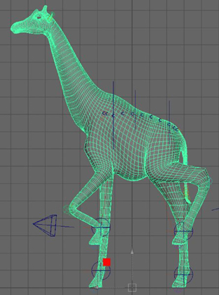
Figure 6.11 The giraffe’s deformations are smoothed by the Delta Mush deformer.
The Delta Mush deformer is easy to use and does not require many setting changes. The deformer’s default settings will usually work in most cases. The following attributes can be used to refine the deformation effects further.
Smoothing Iterations The number of times the smoothing algorithm is applied. The higher the value, the greater the smoothing that occurs. It is possible, however, to smooth your model too much, which results in a loss of detail.
Pin Border Vertices Pinning the border vertices is useful when your model has open edges, for instance, clothing. When turned on, Pin Border Vertices prevents the border vertices from being affected by the smoothing algorithm of the deformer.
Displacement Smoothing will typically cause volume loss in your model. You can use the Displacement attribute to increase the volume of a mesh and likewise decrease its volume. The Displacement channel is restricted to a value between 0 and 1. You can, however, use the Scale values located under the Displacement slider to act as a multiplier to individual axes.
To see a version of the scene to this point, open the deltaMush_v02.ma scene from the chapter6scenes directory at the book’s web page.
Animating Facial Expressions Using Blend Shapes
As the name suggests, a blend shape deformer blends, or interpolates, between variations of a geometric form. A blend shape deformer uses one or more blend shape targets. These targets are duplicates of the original model that have been modified using a variety of modeling techniques.
Animating facial expressions for characters is usually accomplished through the use of blend shapes. Although this is not the only way to animate expressions and speech, it is the most common because it is relatively straightforward to set up and animate. In this section, you’ll learn how to create blend shape targets, paint blend shape weights, create a blend shape deformer, and build a simple facial-animation rig.
You create the blend shape deformer by selecting the targets and the original model and choosing Deform ➢ Blend Shape. The deformer controls consist of sliders—one for each blend shape target. The original model is animated by moving and keyframing the sliders. As the value of a slider moves between 0 and 1, Maya interpolates the change, blending between the original shape and the target shape. The duplicate model is known as the blend shape target, and the original model is known as the base mesh.
You should understand a few things about how blend shapes work before you set up a facial-animation rig. First, blend shapes always move in a straight line when interpolating the change between the original model and the blend shape target. Think of how your eyelids move when you blink. Your eyelid is a flap of skin that moves over the spherical shape of your eyeball. If you make a dot on the edge of your eyelid with a marker (don’t do this—just imagine it) and then follow the path of that dot from a side view, the dot moves in an arc as your eyelid closes.
If you have a model of a face with the eyes open and a blend shape target with the eyes closed, when you create the blend shape deformer and then animate the eyes closing, instead of moving in an arc, the eyelids will move in a straight line from the open position to the closed position. Most likely, the eyelid geometry will pass through the eyeball geometry, creating a less-than-convincing blinking behavior. The middle eye in Figure 6.12 shows the results of blending the first and last eyelid shapes together. Understanding that the blend shape deformer moves in a linear direction from one state to the next is important if you are to develop a solution for this problem.

Figure 6.12 Blend shape deformations move in a straight line, which can cause problems for certain types of facial movements, such as blinking eyelids.
Second, a blend shape target should have the same number of vertices and the same point order as the original geometry. Vertices on polygons and control vertices (CVs) on NURBS geometry are numbered in a specific order. You can see the numbers listed in the Script Editor when the vertices are selected. If the number of points and the order of the points on a blend shape target do not match the original, the deformer will not be created, or it will behave strangely (see Figure 6.13). It is possible to use a blend shape target that has a different number of vertices than the base mesh; however, this can lead to unpredictable results.

Figure 6.13 When the point order of the base mesh and the blend shape target do not match, strange results can occur when the deformer is applied.
Third, when deforming a model with more than one blend shape target, the changes created by the targets are added together. So if you have one blend shape target in which a face is smiling and a second target in which the face is frowning, you may think that one target cancels the other. In fact, setting both blend shape targets to full strength creates a strange result on the base mesh because the smile and the frown will be added together (see Figure 6.14).

Figure 6.14 A smile shape and a frown shape are added together to create a very strange expression.
Creating Blend Shape Targets
The first step in setting up a blend shape facial animation rig is to model the actual blend shapes based on the base mesh. The final rig works something like the controls for a puppet. Rather than animate blend shape targets using a happy face model and a sad face model, you want the blend shape target models built so that they allow you to isolate individual muscle movements. This will give you the most control when animating. When animating a smile, you’ll have controls for the mouth, eyelids, eyebrows, cheeks, and more, so you’ll have the option of animating a smile with brows up for a happy character and a smile with brows down for a menacing character. In addition, you want to isolate the sides of the face so that the corner of one side of the mouth can be animated separately from the corner of the other side of the mouth.
When creating blend shape targets, it’s best to think in terms of what the muscle is doing rather than a particular expression. The same targets are used to animate speech and emotion. So, rather than creating a blend shape target for a smile and a blend shape target for the “eeeee” sound, you want to make a single blend shape target that pulls back a corner of the mouth. Then this blend shape target combined with muscle movements created for other targets can be used for smiling, saying “cheeeese,” or doing both at the same time.
In this exercise, you’ll create blend shape targets for a character’s mouth that can be used for widening the lips as in a smile as well as narrowing the lips as in a kiss. These two shapes (mouthWide and mouthNarrow) will then be separated into four shapes (leftMouthWide, leftMouthNarrow, rightMouthWide, and rightMouthNarrow).
-
Open the
amanda_v01.mascene from thechapter6scenesdirectory at the book’s web page. This scene shows a basic polygon head. -
Select the amanda model, and duplicate it (
Ctrl/Cmd+d). Move the duplicate to the side, as shown in Figure 6.15. Name the duplicatemouthWide.By default, blend shape deformers calculate only shape node-level changes. In other words, only changes made on the vertex level are considered. You can move, rotate, and scale the targets without affecting the base mesh—unless you specify otherwise in the deformer options. This will be discussed further later in the chapter.
- Select the Move tool, and open the Tool Settings dialog box for the tool. Under the Symmetry Settings, activate Symmetry to Object X.
- Turn on Soft Select, and set Falloff Mode to Surface. Set Falloff Radius to
0.10, and add a point to the Falloff Curve value. Set Interpolation to Spline, and adjust the curve to look like Figure 6.16. - Select and then RMB-click the mouthWide geometry, and choose Vertex to switch to vertex selection mode.
- Select a vertex at the corner of the mouth, as shown in Figure 6.17. You’ll see the vertices colored-coded, indicating the Soft Selection radius and falloff. Carefully start moving the corner to the side and back toward the ear.
- Open the Modeling Toolkit, and press
wto activate the Move tool. - Set the Transform Constraint to Surface Slide. By enabling Surface Slide, you allow the transformed vertices to follow the contours of the surface. This helps maintain the shape and volume of your geometry. In terms of blend shape targets, it essentially gives the geometry a solid core to move points along.
-
Expand the Soft Selection rollout. Reset the curve. Change Soft Selection to a value of
0.08, as shown in Figure 6.18.The muscles in the face work in concert to create facial expressions. Most of the face muscles are designed to convey emotion, aid with speech, and keep food in your mouth while you eat. Muscles work in groups to pull parts of the face in various directions like a system of pulleys. When you smile or grimace, the corners of your mouth are pulled back toward the ears by several muscles working together.
Cartoons often simplify the smile by drawing the corners of the mouth upward into a U shape. However, in reality the corners of the mouth move upward only a small degree. The illusion of perspective makes it look as though the mouth is forming a U. The smile shape is not a U shape, but rather the lips are stretched in a nearly straight line across the teeth. To refine the smile, follow these steps:
- It will take a little work to form the smile shape on the face. Use a mirror for reference. Keep in mind that as the lips are pulled across the teeth, they are stretched and lose volume, giving them a thinner appearance.
- As you work, make adjustments to the settings on the Move tool and change the Falloff Radius and Falloff Curve values as needed.
- When the corners of the mouth are pulled back, adjust other parts of the face near the corners and on the lips, but don’t go too far beyond the area of the mouth. Remember, you are making an isolated change in the shape of the mouth, not a complete facial expression.
- In addition to the Move tool, the Artisan brush is useful for sculpting changes in the model. To activate this tool, select the mouthWide model, and choose (from the Modeling menu set) Mesh Tools ➢ Sculpting Tools. To ensure that the changes you make affect both sides of the model, make sure that the Reflection option is activated in the Stroke section. To make the changes a mirror reflection, check Invert Reference Vector.
You can also restrict the effects of your brush by changing the Reference Vector setting under Sculpt Parameters. Setting it to the x-axis allows you to stretch the lips lengthwise without pushing them in any other axis.
Use a combination of the preceding tools to create the mouth shape. The final wide mouth shape should look like a fake smile because there are no changes in the other parts of the face. It’s a good idea to build a little overshoot into your blend shape targets so that you have a wider range with which to work when animating (see Figure 6.19).
-
Save the scene as
amanda_v02.ma.To see a version of the scene to this point, open the
amanda_v02.mascene from thechapter6scenesdirectory at the book’s web page.The next blend shape is the opposite of the smile. For this shape, the mouth needs to be pulled in from the corners.
- Create another duplicate of the amanda model. Name the duplicate
mouthNarrow. Move it to the model’s right side. -
Use the Move tool and the Sculpting Tools to push the sides of the mouth toward the center of the face. The lips should bulge up in the center.
As the lips push together and bulge at the center, there is a slight curling outward. Those parts of the upper and lower lips that touch in the neutral pose become exposed, and the flesh of the lips rolls outward (but just slightly).
- Use the Rotate tool with Soft Select to help create this rolling outward effect. Figure 6.20 shows the finished narrow mouth blend shape target, the base mesh, and the smile blend shape target, respectively.
-
Once you are satisfied with the two mouth shapes, save the scene as
amanda_v03.ma.To see a version of the scene up to this point, open the
amanda_v03.mascene from thechapter6scenesfolder at the book’s web page.
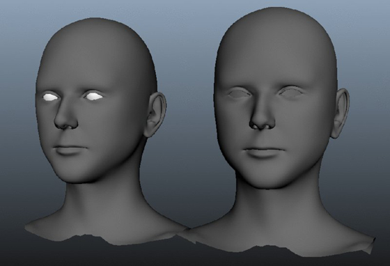
Figure 6.15 A duplicate of the original head model is created.

Figure 6.16 The settings for the Move tool

Figure 6.17 The vertices are color-coded to indicate the falloff strength and radius of the Move tool when Soft Select is enabled.

Figure 6.18 The settings from the Modeling Toolkit

Figure 6.19 The base model (left) and the completed smile blend shape target (right)

Figure 6.20 The completed narrow mouth blend shape target, the base mesh, and the smile blend shape target
Creating Blend Shapes
![]()
To create the blend shape deformer, select all of the targets first and then choose the base mesh. Next, select the Blend Shape deformer from the Deform menu in the Rigging menu set. In this section, you’ll create the deformer using the mouthWide and mouthNarrow shapes.
- Continue with the scene from the previous section, or open the
amanda_v03.mascene from thechapter6scenesfolder at the book’s web page. - Shift+click the mouthWide model and the mouthNarrow model; then Shift+click the amanda model.
- In the Rigging menu set, choose Deform ➢ Blend Shape ➢ ❑. In the Blend Shape Options dialog box, choose Reset Settings from the Edit menu to set the options to the default settings. You want Origin set to Local; this means that only shape node-level changes will be used on the deformer. If the target can be moved, scaled, or rotated, it will not affect how the deformer is applied.
- Name the blend shape deformer
amandaFace(see Figure 6.21). Click Create to make the deformer. - To test the deformer, choose Windows ➢ Animation Editors ➢ Blend Shape. A small pop-up window appears with two sliders. These are the controls for the blend shape deformers.
- Move the sliders up and down, and see how they affect the model (see Figure 6.22). Try putting both sliders at
1to see the shapes added together. Also try setting the values to negative values or values beyond 1. - Save the scene as
amanda_v04.ma.

Figure 6.21 The options for the blend shape deformer

Figure 6.22 The blend shapes are controlled using the blend shape sliders.
To see a version of the scene to this point, open the amanda_v04.ma scene from the chapter6scenes directory at the book’s web page.
Painting Blend Shape Weights
At this point, you have two blend shapes available for animating, mouthWide and mouthNarrow. You may decide that you want additional blend shape targets for the same mouth shape but restricted to just one side of the mouth. This gives you more options for animating a wider variety of facial movements. One easy way to create these additional targets is to use blend shape weighting as a shortcut for making additional blend shape target models from the symmetrical facial poses that you’ve already created.
- Continue with the scene from the previous section, or open the
amanda_v04.mascene from thechapter6scenesdirectory at the book’s web page. - Select the amanda model, and under the Paint Weights section of the Deform menu, choose Blend Shape ➢ ❑.
-
The model turns completely white, and the options open in the Tool Settings dialog box.
In the Target section is the list of all of the current blend shapes applied to the model. The white color on the model indicates that the blend shape weight is at full strength.
- Open the blend shape control window by choosing Windows ➢ Animation Editors ➢ Blend Shape. Set the mouthWide slider to
1so that you can see the deformer applied to the model (see Figure 6.23). - In the Paint Blend Shape Weights Tool dialog box, set Paint Operation to Replace and Value to
0. Click the Flood button. This floods the model with a zero-weight value. The model turns black, and the effect of the mouthWide deformation disappears. -
Set Value to
1, and paint the area around the mouth on the model’s left side. As you paint, you’ll see the left side move into the mouthWide shape within the area painted white (see Figure 6.24). - When you think that you have painted enough of one side of the mouth, select the amanda model and duplicate it (
Ctrl/Cmd+d). Move the duplicate up and off to the side, and name itmouthLeftWide. (Remember to name the deformers based on the character’s left or right side, not your left or right.) - Select the amanda model again, and choose Deform ➢ Blend Shape ➢ ❑ under the Paint Weights section.
- Flood the model with a zero value again, set Value to
1, and this time paint the mouth area on the model’s right side. - Duplicate the model again, and move the duplicate model up and away from the amanda model. Name this duplicate
mouthRightWide. -
Select the amanda model again, and choose Deform ➢ Blend Shape ➢ ❑ under the Paint Weights section. Set Value to
1, and flood the model to return the weight for the mouthWide shape to 1.The two duplicate models will look somewhat strange; this is a very unusual expression (see Figure 6.25). You can use the Artisan brush and the Move tool to make the mouth look more natural, but try to restrict your edits to one side of the mouth or the other. Remember that this particular mouth movement will probably be accompanied by other shape changes during animation, which will make it look more natural. Most likely these shapes will not be used at their full strength, but it’s good to model a little overshoot into the shape to expand the range of possible movements.
- Save the scene as
amanda_v05.ma.

Figure 6.23 Activating the Paint Blend Shape Weights tool turns the model white, indicating that the selected target in the options is applied at full strength to all of the model’s vertices.

Figure 6.24 As the weights are painted, the side of the mouth moves into the mouthWide shape.

Figure 6.25 Two new blend shape targets have been created using the Paint Blend Shape Weights tool.
To see a version of the scene to this point, open the amanda_v05.ma scene from the chapter6scenes directory at the book’s web page.
Adding Targets
![]()
The Blend Shape editor has been redesigned to allow you to add or change your targets. You can add the new targets to the existing blend shape deformer as follows:
- Continue with the scene from the previous section, or open the
amanda_v05.mascene from thechapter6scenesdirectory at the book’s web page. - Select the amanda model, and choose Windows ➢ Animation Editors ➢ Blend Shape to open the blend shape controls.
- Choose the mouthRightWide target, and Shift+click the amanda model. Choose Deform ➢ Blend Shape ➢ Add under the Edit section of the Deform menu. You’ll see a new slider appear in the blend shape controls.
- Repeat step 3 for the mouthLeftWide target (see Figure 6.26).
- Save the scene as
amanda_v06.ma.

Figure 6.26 Sliders are added to the blend shape control window as the additional targets are added to the deformer.
To see a version of the scene to this point, open the amanda_v06.ma scene from the chapter6scenes directory at the book’s web page.
Test the slider controls in the Blend Shape window. You can continue to edit the blend shape targets after they have been added to the deformer. You may want to make additional changes to improve the expressions and the movement between shapes. Remember that at this point, it’s fine to have some strange-looking expressions. The final rig may have dozens of blend shape targets that all work together to create various expressions and facial movements. As long as you have the blend shape targets available, you can continue to refine the expressions by editing the targets.
You can quickly create new blend shape targets from existing targets. This can be helpful when you are making targets that represent small or subtle muscle movements. To do this, make an expression by experimenting with the values in the Blend Shape editor, use the Paint Blend Shape Weights tool to fine-tune, and then duplicate the deformed base mesh to create a new target. You can then add the target to the blend shape node, giving you more sliders and more targets with which to work. In a production situation, a realistic blend shape may consist of hundreds of targets.
Animating a Scene Using Nonlinear Deformers
The nonlinear deformers include the bend, flare, sine, twist, squash, and wave deformers. The names of the deformers give a pretty good indication of what they do. They work well for creating cartoonish effects, and they even do a decent job of faking dynamic effects, saving you from the extensive setup many dynamic simulations require. All of the nonlinear deformers work the same way. The deformer is applied to a surface, a lattice, components, or a group of surfaces, and then parameters are edited to achieve the desired effect. The parameters can be animated as well. You can use nonlinear deformers in combination with each other and with other deformers.
In this section, you’ll use nonlinear deformers to animate a jellyfish bobbing in the ocean. You’ll use just a few of the deformers to create the scene, but since they all work the same way, you can apply what you’ve learned to the other nonlinear deformers in your own scenes.
Creating a Wave Deformer
The wave deformer creates a ring of sine waves like a circular ripple in a puddle. To create the gentle bobbing up and down of a jellyfish, you’ll animate the parameters of a wave deformer.
-
Open the
jellyfish_v01.mascene from thechapter6scenesdirectory at the book’s web page.This scene contains a simple jellyfish model. The model consists of the body of the jellyfish and its tendrils. All the surfaces are NURBS. The tendrils, which were created by converting Paint Effects strokes to NURBS surfaces, are grouped together and then grouped again with the body (see Figure 6.27).
- Select the jellyFish group in the Outliner. In the Rigging menu set, choose Deform ➢ Nonlinear ➢ Wave. The deformer appears as a single line. In the Outliner, you’ll see that a new wave1Handle node has been created.
- Select wave1Handle, and open its Attribute Editor. Click the wave1 tab. The tab contains the parameters for the deformer.
- Set Amplitude to
0.041. The Amplitude increases the height of the sinusoidal wave. This is displayed in the wireframe deformer handle in the viewport. Notice that the jellyfish is now distorted. - Set Wavelength to
0.755. This decreases the distance between the peaks and valleys of the sine wave, creating a long, smooth type of distortion (see Figure 6.28). - Use the following settings to position the wave handle at the center of the jellyfish body:
- Translate X:
0 - Translate Y:
0.787 - Translate Z:
−0.394
- Translate X:
- Set all three Scale channels to
30. - To animate the bobbing motion, create a simple expression that connects the Offset value to the current time. Open the Attribute Editor for wave1Handle to the wave1 tab. In the field next to Offset, type
=timeand press the Enter key. -
Set Min Radius to
0.1. If you switch to wireframe display, you’ll see that a gap has appeared at the center of the deformer handle.The deformer now affects only the areas between the edge of the min radius and the outer edge of the deformer. You can set a range of deformation by adjusting the Min and Max Radius sliders. Dropoff reduces the amplitude of the deformer at the outer edges of the range. Setting Dropoff to
−1would reduce the amplitude at the center of the deformer. - Save the scene as
jellyfish_v02.ma.

Figure 6.27 The jellyfish model is created from groups of NURBS surfaces.

Figure 6.28 The settings on the wave1 tab change the shape of the wave deformer.
To see a version of the scene up to this point, open the jellyfish_v02.ma scene from the chaper6scenes directory at the book’s web page.
Squashing and Stretching Objects
The squash deformer can both squash and stretch objects. It works well for cartoony effects. In this section, you’ll add it to the jellyfish to enhance the bobbing motion created by the wave deformer.
- Continue with the scene from the previous section, or open the
jellyfish_v02.mascene from thechapter6scenesdirectory at the book’s web page. - Make sure that you are still in the Rigging menu set.
- Select the jellyFish group in the Outliner, and choose Deform ➢ Nonlinear ➢ Squash. A node named squash1Handle appears in the Outliner. In the perspective view, the squash handle appears as a long line with a cross at either end.
- Select squash1Handle in the Outliner, and set the Translate channels to the following:
- Translate X:
0 - Translate Y:
1.586 - Translate Z:
0
- Translate X:
- Select the squash1Handle, and open the Attribute Editor to the squash1 tab. The Low and High Bound sliders set the overall range of the deformer. Leave Low Bound at
−1, and set High Bound to0.5(see Figure 6.29).

Figure 6.29 The squash deformer settings appear in the Attribute Editor.
You can animate any of the settings to add motion to the jellyfish. In this case, you’ll add an expression to the Factor setting of squash1. Setting Factor to a positive value stretches the object; setting Factor to a negative value squashes the object. For the jellyfish, animating between squash and stretch helps make the model appear as though it’s floating in water. You can use a sine function as part of an expression that smoothly animates the Factor value between positive and negative values:
-
In the Factor field, type =
squash1.factor=0.25*(sin(time*2));and press the Enter key.Multiplying
timeby 2 speeds up the animation of the values. Multiplying the entire expression by 0.25 keeps the range of values between -0.25 and 0.25. Going beyond this range deforms the jellyfish a bit too much.Factor controls the vertical displacement created by the squash deformer; the Expand setting controls the horizontal displacement created by the effect.
- Set Expand to
2. Set Max Expand Pos to0.78. This places the vertical position of the center of the effect along the length of the deformer. - Save the scene as
jellyfish_v03.ma.
To see a version of the scene to this point, open the jellyfish_v03.ma scene from the chapter6scenes directory at the book’s web page.
Twisting Objects
The twist deformer twists an object around a central axis. You’ll add this to the jellyfish to create some additional motion for the tendrils.
- Continue with the scene from the previous section, or open the
jellyfish_v03.mascene from thechapter6scenesdirectory at the book’s web page. - In the Outliner, expand the jellyFish group and select the tendrils group.
- Choose Deform ➢ Nonlinear ➢ Twist. A new twist1Handle node will appear in the Outliner.
- Select twist1Handle in the Outliner, and set the Translate channels to the following:
- Translate X:
0 - Translate Y:
−18 - Translate Z:
0
- Translate X:
- Open the Attribute Editor for twist1Handle to the twist1 tab.
Just like for the squash deformer, you can specify the range of the effect of the deformer using the Low Bound and High Bound sliders:
-
Set Low Bound to
−1and High Bound to0.825.The Start Angle and End Angle values define the amount of twist created along the object. If you move the End Angle slider, the top of the tendrils spin around even if they are outside of the High Bound range. Moving the Start Angle slider twists the tendrils at their ends, which is more like the effect that you want. You can use a simple noise expression to create a smooth type of random oscillation between values. Since the Start Angle is specified in degrees, you can multiply the noise expression by 360 to get a full range of twisting motion.
- In the Start Angle field, type
=360*(noise(time*0.1));. Multiplyingtimeby 0.1 slows down the motion of the twisting. - Rewind and play the animation. You’re on your way to creating an interesting jellyfish motion (see Figure 6.30).
- Save the scene as
jellyfish_v04.ma.

Figure 6.30 The jellyfish is animated using a number of nonlinear deformers.
To see a version of the scene to this point, open the jellyfish_v04.ma scene from the chapter6scenes directory at the book’s web page.
Creating a Jiggle Effect
A jiggle deformer is a simple way to add a jiggling motion to deformed objects. Jiggle deformers do not have the same level of control as dynamic systems, such as nucleus, fluids, or hair. Jiggle deformers are best used as a substitute for dynamics when the situation requires just a little jiggly motion.
Applying Jiggle Deformers
There aren’t very many options for creating jiggle deformers. To apply a jiggle deformer, select the object that you want to jiggle and create the deformer. In this section, you’ll add the jiggle to the jellyfish:
- Continue with the scene from the previous section, or open the
jellyfish_v04.mascene from thechapter6scenesdirectory at the book’s web page. - Select the jellyFish group in the Outliner. Choose Deform ➢ Jiggle ➢ Jiggle Deformer ➢ ❑.
- In the Create Jiggle Deformer Options dialog box, set Stiffness to
0.1and Damping to0.8. A higher Stiffness setting creates more of a vibrating type of jiggle; lowering the Stiffness value makes the jiggle more jellylike. -
Click Create to make the deformer. You won’t see any new nodes appear in the Outliner because the Display option is set to DAG Objects Only.
If you turn off the DAG Objects Only option in the Outliner, you’ll see that a jiggle deformer is created for each surface. A jiggle cache is created to aid in the calculation and playback of the scene (see Figure 6.31).
- Rewind and play the scene; you’ll see that the jellyfish has a jiggling motion, especially in the tendrils.

Figure 6.31 A node for each jiggle deformer applied to the surfaces appears in the Outliner.
If you want to edit the settings of all of the jiggle deformers at once (since there are so many tendrils, a lot of deformer nodes were created), disable the DAG Objects Only option in the Outliner’s Display menu, Shift+click all of the jiggle nodes (not the jiggle cache nodes), and then edit the settings in the Channel Box. When you have multiple objects selected, editing the settings in the Channel Box applies the settings to all of the selected objects. This is not true when you are working in the Attribute Editor.
Painting Jiggle Weights
The jiggle effect looks good in the area of the tendrils, but it’s a little too strong on the top of the jellyfish body. You can edit the weights of the deformer interactively using the Paint Jiggle Weights tool:
- Select the jellyFishBody node in the Outliner, and choose Deform ➢ Jiggle under the Paint Weights section.
- In the Tool Settings dialog box, set Paint Operation to Replace and Value to
0. Paint the area at the top of the jellyfish body. - Set Paint Operation to Smooth, and click the Flood button a few times to smooth the overall weighting (see Figure 6.32).
- Rewind and play the animation. The jiggling is not quite as strong on the top of the jellyfish.
- Save the scene as
jellyfish_v05.ma.

Figure 6.32 Paint the weights of the jiggle deformer on the top of the jellyfish body and then smooth them using the Flood button.
To see a version of the scene to this point, open the jellyfish_v05.ma scene from the chapter6scenes directory at the book’s web page.
Optimizing Animations with the Geometry Cache
When you create a cache for animated geometry, a series of files written to your computer’s hard drive store the position of each of the points of the specified geometry over time. Geometry caches are used to optimize the performance of an animation. As your scenes become filled with complex animated characters that interact with environments and effects, playback performance can get bogged down, making the scene frustrating to work with. By using geometry caches, you can store that animation data on the hard drive as a separate file, thus freeing up resources so that your computer can more easily play the animation and ensuring that you’ll have a much easier time working on other aspects of the scene, such as lighting, effects, or other animated elements.
Once you create a geometry cache, you can add more deformers and animation to the cached geometry and even alter the playback speed of the cached geometry.
In this section, you’ll get a sense of how you can use a cache by creating one for the jellyfish animated in the previous section. Then you’ll see how you can use the Cache settings to slow the playback of the jellyfish so that the floating motion looks more natural. This is just one example of a creative use of the geometry cache.
Creating a Geometry Cache
The motion-deformed jellyfish looks pretty good as a simple animation. However, after all of the deformers have been combined and the jiggle has been added, the motion looks a little too fast for a convincing deep-sea environment. Obviously, you can continue to edit the expressions used on the deformers, but in this section you’ll take a shortcut by using a geometry cache.
- Continue with the scene from the previous section, or open the
jellyfish_v05.mascene from thechapter6scenesdirectory at the book’s web page. To create a geometry cache, you need to select the geometry nodes; selecting group nodes or parents of the geometry nodes won’t work. - In the Outliner, hold the Shift key and click the plus sign next to the jellyfish group to expand this group and the tendrils group at the same time.
- Shift+click all of the tendril objects and the jellyFishBody surface.
- From the Rigging menu set, choose Cache ➢ Geometry Cache ➢ Create New Cache ➢ ❑.
- In the Create Cache Options dialog box, use the Cache Directory field to specify a directory for the cache. By default, the cache is created in the
Datafolder for the current project. If you will be rendering across computers on a network, make sure that all of the computers have access to the directory that contains the cache. - Name the cache
jellyfish. Set File Distribution to One File and Cache Time Range to Time Slider. - Click Create to make the cache. Maya will play through the animation and write the cache files to disk.
- When Maya has completed the cache, it should automatically be applied to the jellyfish. To prove this, you can select the deformers in the scene, delete them, and then play back the animation. The jellyfish should still bob up and down.
Editing the Cache Playback
Once the cache has been created, you can use the settings in the cache node to change the speed of the playback. This will create a more believable motion for the jellyfish.
- Select any of the surfaces in the jellyfish (not the jellyfish group node), and open the Attribute Editor.
- Switch to the jellyfishCache1 tab. Set the Scale attribute to
5. This scales the length of the animation to be five times its original length, thus slowing down the speed of playback (see Figure 6.33). - Set the length of the timeline to
1000. The original 200-frame animation has been scaled to 1,000 frames. -
Create a playblast. You’ll see that the jellyfish is now much slower, and it looks more like an undersea creature.
Once you have created a cache, you can add other deformers, animate the movement of the jellyfish group, and even make animated copies.
- Select the jellyFish group, and choose Edit ➢ Duplicate Special ➢ ❑.
- In the Duplicate Special Options dialog box, set Geometry Type to Instance. Click Duplicate Special to create the copy.
- Move the copy away from the original, and rotate it on its y-axis so that it does not look exactly like the original.
- Make a few more copies like this to create a small jellyfish army. Play back the animation to see the army in action (see Figure 6.34).

Figure 6.33 The options for the Cache playback

Figure 6.34 Duplicates of the original jellyfish are created to make a small jellyfish army.
To create variations among the jellyfish, you can create three or four original jellyfish animations that have differences in their deformer settings and create a different cache for each. Then create several sets of instances for each jellyfish. Position them strategically in the camera view, and vary their Y-rotations.
Applying Motion Capture
![]()
Capturing the motion of a real person used to require tens of thousands of dollars and enough floor space to park a jet. Nowadays, all you need is an Xbox Kinect to have your own motion-capture system. If the Kinect isn’t appealing, don’t worry—there are hundreds of motion-capture files that you can download, most of which are free. Motion capture has become extremely available. In the following example, we’ll take a look at how to apply existing motion capture to the Human Inverse Kinematics (HIK) character rig that you created in Chapter 5, “Rigging and Muscle Systems.”
-
Open the
hikCharacter_v01.mascene from thechapter6scenesdirectory at the book’s web page. - You can download numerous motion-captured files from
https://creativemarket.com/apps/mayalt. Download HIK & Mocap Samples. Find and import thewalkSit.mafile into a viewport. - The scene file is imported into your existing scene. You probably won’t see anything show up. This is because the imported assets are much bigger than the HIK character. Press
ato frame all. Figure 6.35 shows the extreme differences between the two character rigs. - Choose Skeleton ➢ Human IK to open the Character Controls window.
- In the Character Controls window, make sure that Character is set to Character1. Change Source to MocapExample. Use Figure 6.36 as a guide.
- The character updates with the motion capture. Zoom out if you can’t see the skeleton anymore.
- The animation is 122 frames long. Change the timeline to match, and then click Play to watch the motion. The HIK now uses the motion of the motion-capture example regardless of the difference in scale between the two skeletons.
-
The motion capture is applied directly to the HIK skeleton, bypassing the control handles. You can bake the animation to the controllers. Under the Character Controls menu button (the large blue icon in the upper-left corner), choose Bake ➢ Bake To Control Rig. The default options work perfectly for this example.
Maya creates a key at every frame. When done, the control rig is automatically applied to the character. You can now play the animation as you did before.

Figure 6.35 The imported motion capture example is much larger than the HIK rig.

Figure 6.36 Apply the motion-capture example by changing the source in the Character Controls window.
With the motion applied to the control rig, you can add animation on top of an animation layer or to the control handles directly. To see a version of the final scene, open the mocap_v01.ma scene from the chapter6scenes directory at the book’s web page.
The Bottom Line
Work with deformers. Maya has a multitude of deformers that can be used to animate or model any object with control points. Deformers provide real-time results, making them easy and flexible to work with.
Master It Create a planet with a terrain filled with craters.
Animate facial expressions. Animated facial expressions are a big part of character animation. It’s common practice to use a blend shape deformer to create expressions from a large number of blend shape targets. The changes created in the targets can be mixed and matched by the deformer to create expressions and speech for a character.
Master It Create blend shape targets for the amanda character. Make an expression where the brows are up and another where the brows are down. Create a rig that animates each brow independently.
Animate nonlinear deformers. Nonlinear deformers apply simple changes to geometry. The deformers are controlled by animating the attributes of the deformer.
Master It Animate an eel swimming past the jellyfish that you animated in this chapter.
Add jiggle movement to an animation. Jiggle deformers add a simple jiggling motion to animated objects.
Master It Add a jiggling motion to the belly of a character.
Apply motion capture. Maya comes with several motion-capture animations. You can access them through the Visor.
Master It Switch between multiple motion-capture examples on the same character.