
Chapter 7
Lighting with mental ray
To achieve professional-quality, realistic renders in the Autodesk® Maya® program, you need to master the mental ray® render plug-in that comes with Maya. mental ray is a complex rendering system that is incorporated through the Maya interface. Learning how to use it properly and efficiently takes time, study, and practice. Chapter 8, “mental ray Shading Techniques,” Chapter 9, “Texture Mapping,” and Chapter 11, “Rendering for Compositing,” discuss various aspects of working with mental ray.
This chapter is concerned with using mental ray lighting tools and techniques to create realistic renders. Options available within mental ray allow you to achieve a wide variety of effects. You won’t need to use all of them in every case, but a good understanding of what is available will help you make better decisions when approaching a lighting problem in a scene.
In this chapter, you will learn to
- Use shadow-casting lights
- Render with global illumination
- Render with Final Gathering
- Use image-based lighting
- Render using the Physical Sun and Sky network
- Understand mental ray area lights
Shadow-Casting Lights
![]()
You can create two types of shadows in mental ray: cast shadows and ambient occlusion. Several methods are available for creating them. Any combination of cast shadows and ambient occlusion can be used in a mental ray scene:
Cast Shadows Cast shadows are created when an object blocks the rays of light coming from a light source. Cast shadows are the most familiar type of shadow. They are a good indication of the type, location, and orientation of the light source casting the shadow.
Ambient Occlusion Ambient occlusion occurs when indirect light rays are prevented from reaching a surface. Ambient occlusion is a soft and subtle type of shadowing. It’s usually found in the cracks and crevices of 3D objects and scenes.
In this section, you’ll create and tune cast shadows using lights in mental ray. Ambient occlusion is discussed later in the chapter, in the sections “Indirect Lighting: Global Illumination” and “Indirect Illumination: Final Gathering,” as well as in Chapter 11, “Rendering for Compositing.”
A light source in a Maya scene casts either raytrace or depth map shadows. When you create a light in Maya, its shadows are set to raytrace by default. You can use depth map and raytrace shadows together in the same scene, but each light can cast only one or the other type of cast shadow.
Shadow Preview
When you create a shadow-casting light in a Maya scene, you can preview the position of the shadow in the viewport window.
This scene shows a bicycle. The shaders used for the vehicle are simple standard Maya Blinn materials. When you’re setting up lights for a scene, it’s usually a good idea to use simple shaders as you work. This makes test rendering faster, and it also keeps the focus on how the lighting will work within the composition. Later, as you refine the lighting of the scene, you can add more complex shaders and textures.
- Open the
bicycle_v01.mascene from thechapter7chapter7scenesfolder at the book’s web page (www.sybex.com/go/masteringmaya2016). -
Create a spot light by choosing Create ➣ Lights ➣ Spot Light.
To position the spot light, use the Move and Rotate tools. You can also look through the light as if it were a camera, which is often a faster and easier way to place the light in the scene.

- Select the spot light and, from the viewport toolbar, choose Panels ➣ Look Through Selected. Use the Alt/Option+MMB and the Alt/Option+RMB key combinations to move the view so that you can see the model from above (see Figure 7.1).
- The green circle at the center of the view represents the cone angle of the spot light. Open the Attribute Editor for the spotLight1 object, and click the spotLightShape1 tab. Set Cone Angle to 90. The light from the spot light now covers more area in the scene.
- In the viewport toolbar, choose Lighting ➣ Shadows; this option is available only when Use All Lights has been activated. Choose Use All Lights through the menu or press 7 on the keyboard.
You won’t see any shadows until you activate shadows for the lights in the scene.
- Select the spotLight1 object, open its Attribute Editor, and click the spotLightShape1 tab.
- Expand the Shadows section, and activate Use Depth Map Shadows. A preview of the shadow appears on the ground plane (see Figure 7.2).
- Select the spot light, and use the Move and Rotate tools to change its position and rotation. Observe the changes in the preview. The preview will most likely slow down the performance of Maya, so use this feature only when you are positioning lights.
- Scroll to the top of the spot light attributes, and set Type to Directional. (The shadow preview works only for spot lights and directional-type lights.) Notice the difference in the shape of the shadow.
- Switch Type back to Spot Light, and set the cone angle back to 90.
- Save the scene as
bicycle_v02.ma.

Figure 7.1 View the scene from the position of the spot light.

Figure 7.2 Activate a preview of the spot light’s shadow in the scene.
To see a version of the scene, open the bicycle_v02.ma file from the chapter7scenes folder at the book’s web page.
Depth Map Shadows
![]()
Depth map shadows (also known as shadow maps) are created from data stored in a file that is generated at render time. The file stores information about the distance between the shadow-casting light and the objects in the scene from the light’s point of view. Depth map shadows usually take less time to render than raytrace shadows and produce excellent results in many situations.
When using mental ray, you can choose to use the native depth map shadows in Maya or mental ray’s own depth map format. In this exercise, you will compare the results produced using various depth map shadow settings.
-
Open the
streetCorner_v01.mascene from thechapter7scenesfolder at the book’s web page. This scene shows a section of a city street corner.All of the objects in the scene have been assigned to lambert1. Using a simple Lambert shader speeds up the render and allows you to focus on how the shadows look on the surfaces without the distraction of reflections and specular highlights.
-
Open the Render Settings window (Windows ➣ Rendering Editors ➣ Render Settings), and make sure that mental ray is the selected option in the Render Using menu.
-
Switch to the Quality tab; then go to the menu bar at the top of the Render Settings window and choose Presets ➣ Load Preset to load the Production preset (see Figure 7.3).
- Open the Attribute Editor for spotLight1, and click the spotLightShape1 tab.
- Scroll down to the Shadows section. Check Use Depth Map Shadows. Turn this option on whenever you want to use depth map shadows.
- Choose Windows ➣ Rendering Editors ➣ Render View to open the Render View window, where you can preview your renders as you work. As you create renders, you can store the images and compare them with previous renders.
- From the Render View menu, choose Render ➣ Render ➣ streetCorner_CAM.

Figure 7.3 Choose the Production preset from the mental ray Presets menu.
You’ll see the render appear in the window after a few seconds. By default, the quality of depth map shadows is pretty poor. With some tweaking, you can greatly improve the look of the shadows.
The shadow is generated using a special depth file, which is an image. As such, the image has a resolution that is controlled by the Resolution slider. When the resolution is low, you can see a grainy quality in the shadows, as shown in Figure 7.4.

Figure 7.4 The default depth map shadows have a grainy quality.
To improve the look of the shadow, you can balance the resolution with the filter size:
- In the Depth Map Shadow Attributes section of the spotLightShape1 tab, set Resolution to 2048 and Filter Size to 0.
- Create a test render in the render view, and store the image in the Render View window (in the Render View window, choose File ➣ Keep Image In Render View). The shadow is improved and relatively free from artifacts.
- Set Resolution to 512 and Filter Size to 4.
- Create a test render, store the render in the Render View window, and use the scroll bar at the bottom of the render view to compare the two images (see Figure 7.5).

Figure 7.5 Two renders using depth map shadows. The left side uses a high-resolution map with no filtering; the right side uses a low-resolution map with high filtering.
Using a low resolution (such as 512) and a high filter size (such as 4), as shown on the right side of Figure 7.5, creates soft shadows—the kind you might expect on an overcast day. One weakness in using a high filter size is that the blurring is applied to the entire shadow. In reality, shadows become gradually softer as the distance increases between the cast shadow and the shadow-casting object.
The Use Mid Dist feature is enabled by default. This option corrects banding artifacts that can occur on curved and angled surfaces. The Mid Dist Map is a second image file that records the points midway between the first and second surfaces encountered by the light. The second image is used to modify the depth information of the original depth map file to help eliminate banding artifacts. This image is created internally, unless you turn on Disk Based Dmaps.
The Bias slider provides a similar function for eliminating artifacts. The slider adjusts the depth information in the depth map file. Increasing the bias pushes surface points closer to the shadow-casting light to help eliminate artifacts. This transformation of surface points occurs in the depth map file, not in the actual geometry of the scene.
If you are encountering artifacts on the surface of objects and Use Mid Dist is enabled, you can use the Bias slider to reduce the artifacts. Change the bias values in small increments as you create test renders. If the bias is too high, you’ll see a gap between the shadow-casting object and the shadow.
The Use Auto Focus setting automatically adjusts the objects within the field of the light’s viewable area to the maximum size of the shadow map resolution. Thus if from the light’s point of view an object is surrounded by empty space, the light will zoom into the object in the depth map image. This helps optimize the use of the pixels within the depth map image so that none are wasted. It’s usually a good idea to leave this setting enabled when using spot lights; however, you may encounter a different situation with other types of lights.
![]()
Now try this:
- Set Resolution of the depth map to 512 and Filter Size to 0.
- Scroll up in the Attribute Editor, and set the light Type to Directional.
- Create a test render.
The shadow is very blocky when the light is switched to directional (see Figure 7.6).
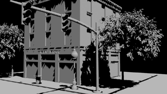
Figure 7.6 Depth map shadows cast by directional lights appear very blocky.
When you use spot lights, the size of the viewable area from the light’s point of view is restricted by the cone angle and the distance between the light and the subject. When you use directional lights, the size of the viewable area is always adjusted to fit all of the objects in the scene. This is because directional lights do not factor in their position in the scene when calculating shadows, only their orientation.
In this situation, you can use the new Shadow Map Camera feature described in the next section, “mental ray Shadow Map Overrides.”
mental ray Shadow Map Overrides
The mental ray overrides offer settings that are similar to those for the standard Maya shadow maps. In addition to the Resolution setting, there are Samples and Softness settings. The Softness setting is similar to the Filter Size attribute for Maya shadow maps. You can click the Take Settings From Maya button to load the settings created for standard Maya shadow maps automatically into the mental ray attributes:
- Open the
streetCorner_v02.mascene from thechapter7scenesfolder at the book’s web page. In the Render Settings window, make sure that Render Using is set to mental ray. Switch to the Quality tab, and make sure that the Production preset is loaded. - Select the spot light, and open the Attribute Editor to the spotLightShape1 tab. In the Shadows section, make sure that Use Depth Map Shadows is on.
- Scroll down to the Attribute Editor, expand the mental ray rollout, and expand the Shadows section under mental ray.
- Check the Use mental ray Shadow Map Overrides box. This activates the Shadow Map Overrides section, giving you access to mental ray controls for shadow maps.
- Set Resolution to 2048 and Softness to 0.025.
- Create a test render. Store the image in the Render View window. The render is similar to the results seen before—in other words, it’s very grainy.
-
Set Samples to 64, and create another test render. The graininess is reduced without significantly impacting the render time. Store the image in the render view.
Detail shadow maps are a more advanced type of shadow map that stores additional information about the surface properties of shadow-casting objects. This information includes surface properties such as transparency. The render takes longer, but the shadows are improved.
- Set Shadow Map Format to Detail Shadow Map (see Figure 7.7), and create another render.
- Use the scroll bar at the bottom of the render view to compare this render with the previous two renders (see Figure 7.8).
- Save the scene as
streetCorner_v03.ma.
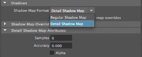
Figure 7.7 Enable Detail Shadow Map in the mental ray Shadows settings.

Figure 7.8 The street corner is rendered with Samples set to 1 (left image), Samples set to 64 (middle image), and Detail Shadow Map enabled (right image).
Rendering with Detail Shadow Maps enabled will take more time, but the quality is improved. Detail shadow maps are more sensitive to changes in the Softness setting in the Shadow Map Overrides rollout. There are also additional Samples and Accuracy settings in the Detail Shadow Maps rollout that can be used to tune the quality of the maps. You can use the Shadow Map File Name field to set a name for saved shadow maps and then reuse the shadow maps to improve render time as long as the lights or shadow-casting objects are not animated. The settings for saving shadow maps are found in the Shadows section of the Render Settings window on the Quality tab.
The bottom line is that when using depth map shadows, you can use a number of options to improve the quality of the shadows. The goal is to strike a balance between render time and quality.
To see a version of the scene up to this point, open the streetCorner_v03.ma scene from the chapter7scenes folder at the book’s web page.
Raytrace Shadows
![]()
Raytrace shadows are created by tracing the path of light rays from the light source to the rendering camera. Using raytrace shadows produces more accurate results, but it often takes a little more time and processor power to calculate. This has become less of an issue in recent years because of improvements in computer processor speeds, and it is now the default setting in Maya.
These are some advantages raytrace shadows have over shadow maps:
- Raytrace shadows created with area lights become softer and lighter as the distance increases between the shadow and the shadow-casting object.
- Raytrace shadows can be accurately cast from transparent, refractive, and colored objects.
- Raytrace shadows support indirect lighting methods.
To activate raytrace shadows, make sure to enable Use Ray Trace Shadows on each light. When you choose the Production quality preset for mental ray, Raytracing is enabled by default (see Figure 7.9).

Figure 7.9 Use Ray Trace Shadows is enabled for the light.
Raytrace shadows are typically very crisp when enabled. To add softness to the shadow, increase the Shadow Rays and Light Radius values in the Raytrace Shadow Attributes section. In Figure 7.10, you can see how increasing the Light Radius and Shadow Rays values adds softness to the shadow. The render in the left image uses a Light Radius of 0 and a Shadow Rays setting of 1. The render in the right image has a Light Radius of 3, and Shadow Rays is set to 20. Notice that the blurring on the shadow increases as the distance between the shadow and the shadow-casting object increases.

Figure 7.10 Add softness to raytrace shadows by increasing the Light Radius and Shadow Rays settings.
The Light Radius setting is giving the light a random position within the given radius for each pixel of shadow. Since the position of directional lights is of no consequence, their shadows are softened with a channel called Light Angle, which randomizes the angle of the light.
Increase the Ray Depth Limit value when you need a shadow to be visible in reflections. Each level of the Ray Depth Limit corresponds to the number of raytrace bounces the light will calculate before the shadow is no longer visible (see Figure 7.11).

Figure 7.11 When Ray Depth Limit is set to 1, the shadow is not visible in the reflection (left image). When it is set to 2, the shadow is visible (right image).
Indirect Lighting: Global Illumination
In reality, when a ray of light hits an opaque surface, it is either absorbed or reflected (or a little of both) by the surface. If the light ray is reflected, it reenters the environment and continues to bounce off reflected surfaces until it is absorbed by another surface. Objects illuminated by reflected light are thus lit indirectly.
As light rays bounce around in an environment, fewer of them reach the parts that are hidden in corners, cracks, and crevices. The lack of light in these areas creates a type of shadowing known as ambient occlusion. You can see ambient occlusion shadowing in the crevices of the photograph in Figure 7.12.

Figure 7.12 Ambient occlusion refers to the shadowing effect seen in the crevices of this photograph.
mental ray has three methods for simulating indirect lighting and ambient occlusion shadowing: the Global Illumination, Final Gathering, and Ambient Occlusion shaders. You can use them separately or together depending on what you are trying to achieve in your render.
In this section, you’ll get some hands-on experience working with global illumination; the next section covers Final Gathering. Using ambient occlusion will be discussed along with ambient occlusion render passes in Chapter 11.
Global illumination simulates photons of light bouncing off geometry in a Maya scene. Autodesk Maya 2016 greatly simplifies rendering global illumination. It is no longer necessary to control the photons of individual lights. Photon emission happens automatically.
In this exercise, you’ll use global illumination to light a hospital room. There are no textures or colors in the scene, so you can focus specifically on how global illumination reacts with surfaces.
![]()
- Open the
hospitalRoom_v01.mascene from thechapter7scenesfolder at the book’s web page. In the scene, a camera named renderCam has already been created and positioned. - Create a directional light, and place it outside the window.
- Rotate the light so that it’s shining in the window (the position of a directional light does not affect how it casts light—only the rotation does—but it’s convenient to have it outside the window). Use these settings in the Channel Box:
- Rotate X: −141.753
- Rotate Y: 22.931
- Rotate Z: 15.26
- Create a test render in the render view using the renderCam camera. The image should look dark except for the light shining through the blinds of the window.
- Open the Render Settings window, and switch to the Quality tab.
- Under the Sampling rollout, change Indirect Diffuse (GI) Mode to On (GI Prototype).
- Create another test render. The resulting render is still dark, but notice how light is spilling into the scene from the window.
Using a directional light is a perfectly reasonable choice for creating the look of light coming through a window. The light rays cast by a directional light are parallel, which simulates the way light from a distant source, such as the sun, behaves (see Figure 7.13).

Figure 7.13 The directional light casts a shadow from the blinds.
The photon-casting properties of a light are completely separate and unrelated to the light’s intensity. In practice, it’s often a good idea to use one light to cast direct light as well as to create cast shadows and another light to create the indirect light.
If you are in a situation where the same light is casting direct and indirect illumination, raising the intensity can cause the area around the light to become overexposed. In this situation, you may want to use two lights as follows:
- Rename the directional light to Sun.
- Create an area light (Create ➣ Lights ➣ Area Light).
- Place the light near the wall opposite the window. Name the light Bounce. You can use these settings in the Channel Box:
- Translate Y: 7.0
- Translate Z: 12.0
- Open the Attribute Editor for Bounce. Turn off Emit Diffuse and Emit Specular.
-
Create a test render of the scene, and store the image in the Render View window.
The render is a big improvement. The default settings still require some tuning, but the scene is now illuminated with bounced light.
- The image looks a little weird because there is sunlight coming through a black window. To create a quick fix for this, select renderCam and open its Attribute Editor.
- In the Environment rollout, set the Background Color to white. Create another test render (see Figure 7.14).
- Save the scene as
hospitalRoom_v02.ma.

Figure 7.14 Photons are cast from an area light placed opposite the window, inside the room. When the background color for the camera is set to white, the area outside the window is white.
To see a version of the scene up to this point, open the hospitalRoom_v02.ma scene from the chapter7scenes folder at the book’s web page.
Color Bleeding
When light is reflected from a colored surface, the color of that surface affects the color of the light reflecting from it. mental ray’s global illumination simulates this property.
- Open the
hospitalRoom_v03.mascene from thechapter7scenesfolder at the book’s web page. This scene has a bucket added close to where the sunlight strikes the floor and the wall. - The model has a Lambert shader applied with bright red set for the color. Create a test render. You’ll see the red color bleed onto the surrounding area.
Color bleeding is a part of global illumination and occurs automatically when colored objects are near the photon-emitting lights.
Indirect Illumination: Final Gathering
Final Gathering is another method for calculating indirect lighting. It can be used on its own or in conjunction with global illumination. Final Gathering uses irradiance sampling and ambient occlusion to create the look of ambient and indirect lighting. When Final Gathering is enabled, rays are cast from the camera into the scene. When a ray intersects with a surface, a Final Gathering point is created that samples the irradiance value of the surface and determines how it is affected by other scene elements, such as nearby objects, lights, and light-emitting surfaces.
Final Gathering uses raytracing rather than photon casting. Each Final Gathering point that the camera shoots into the scene lands on a surface and then emits a number of Final Gathering primary rays, which gather information about the irradiance values and proximity of other scene elements. The information gathered by the rays is used to determine that the surface is shading normal at the Final Gathering point. Imagine a hemispherical dome of rays that are emitted from a point on a surface; the rays gather information about other surfaces in the scene. Like global illumination, this allows it to simulate color bleeding from nearby surfaces.
Light-Emitting Objects
One of the most interesting aspects of Final Gathering is that you can use objects as lights in a scene. An object that has a shader with a bright incandescent or ambient color value actually casts light in a scene. This works particularly well for situations in which geometry needs to cast light in a scene. For example, a cylinder can be used as a fluorescent lightbulb (see Figure 7.15). When a shader is assigned to the cylinder with a bright incandescent value and Final Gathering is enabled, the result is a very convincing lighting scheme.

Figure 7.15 A cylinder with an incandescent shader casts light in the scene when Final Gathering is enabled.
In this exercise, you’ll light the bicycle seen earlier in the chapter using only objects with incandescent shaders. Polygon planes will be used as “light cards” to simulate the look of diffuse studio lighting. You’ll find that it’s easy to get a great-looking result from Final Gathering rendering while still using simple, standard Maya shaders.
![]()
- Open the
bicycle_v01.mascene from thechapter7scenesfolder at the book’s web page. - Open the Render Settings window. Make sure that you are using mental ray for the renderer and click the Common tab.
-
Scroll to the bottom of the window, and expand the Render Options rollout. Make sure that the Enable Default Light option is not checked.
The Enable Default Light option is normally on so that when you create a test render in a scene with no lights, you can still see your objects. When you add a light to the scene, the default light is overridden and should no longer illuminate the objects in the scene. However, since you won’t be using actual lights in this scene, you need to deselect Enable Default Light.
- Switch to the Quality tab, and set Quality Presets to Production.
- Create a quick test render using the renderCam camera. The scene should appear completely black, confirming that no lights are on in the scene.
- Under the Sampling rollout in the Quality tab, set the Indirect Diffuse (GI) Mode to Finalgather.
- Do another test render. The scene should still be black.
- Select the renderCam camera in the Outliner, and open its Attribute Editor.
- Switch to the renderCamShape tab, scroll down to the Environment section, and set Background Color to white.
-
Create another test render. Make sure renderCam is chosen as the rendering camera.
You’ll see the bicycle appear as the scene renders. There are no lights in the scene. However, the white color of the background is used in the Final Gathering calculations. You’ll notice that the scene renders twice.The Final Gathering render takes place in two stages:
- In the first pass, Final Gathering projects rays from the camera through a hexagonal grid that looks like a low-resolution version of the image.
-
In the second stage, the Final Gathering points calculate irradiance values, and the image is actually rendered and appears at its proper quality.
You’ll often notice that the first pass appears brighter than the final render.
The bicycle has simple shaders applied and no textures. The shadowing seen under the bicycle and in the details is an example of ambient occlusion that occurs as part of a Final Gathering render (see Figure 7.16).
- Set Background Color of renderCam to black.
- Create a polygon plane, and apply a Lambert shader to the plane.
- Set the Incandescence option of the plane’s Lambert shader to white.
- Use the Move and Rotate tools to position the plane above the bicycle at about a 45-degree angle. Use the following settings in the Channel Box for the plane:
- Translate X: 0.0
- Translate Y: 36.0
- Translate Z: 25.0
- Rotate X: 45
- Rotate Y: 0
- Rotate Z: 0
- Scale X: 40
- Scale Y: 20
- Scale Z: 20
- Select the plane, and open the Attribute Editor to the pPlaneShape2 tab.
- Expand the Render Stats rollout, and turn off Primary Visibility. This means that the plane still influences the lighting in the scene and can still be seen in reflections and refractions, but the rendering camera does not see the plane itself.
- Create another test render from the renderCam camera. The bicycle appears much darker this time.
- Select the pPlane2 shape, and open the Attribute Editor.
- Select the tab for the plane’s Lambert shader, and click the swatch next to Incandescence to open the Color Chooser.
- Set the slider mode to HSV using the menu below the Color Chooser. Set the value slider (V) to 4.
-
Create another test render. The bicycle should be more visible now compared to its appearance in the test render from step 17 (see Figure 7.17).
Using incandescent objects is a great way to simulate the diffuse light boxes used by photographers. You can easily simulate the lighting used in a studio by strategically placing incandescent planes around the bicycle. However, you’ll notice that the lighting is somewhat blotchy.
The white polygon is reflected in the surface of the bicycle. The shader that is applied to the body is a very simple Phong-type shader, and it looks pretty good.
- Save the scene as
bicycle_v03.ma.

Figure 7.16 The bicycle is rendered with no lights in the scene. The camera’s Background Color value is used to calculate the Final Gathering points.

Figure 7.17 Raising the value of the incandescence on the shader’s plane increases the illumination on the bicycle.
To see a version of the scene up to this point, open the bicycle_v03.ma scene from the chapter7scenes folder at the book’s web page.
![]()
Using Lights with Final Gathering
The previous exercises demonstrated how Final Gathering can render a scene without lights by using only incandescent objects. However, for many situations, you’ll want to combine Final Gathering with lights so that specular highlights and clear shadows are visible in the render. If you take a look outside on a sunny day, you’ll see examples of direct lighting, cast shadows, indirect lighting, and ambient occlusion working together. Likewise, a typical photographer’s studio combines bright lights, flashbulbs, and diffuse lights to create a harmonious composition. You’ll also find that combining lights and Final Gathering produces a higher-quality render.
Image-Based Lighting
Image-based lighting (IBL) uses the color values of an image to light a scene. This can often be done without the help of additional lights. When you enable IBL, you have the choice of rendering the scene using Final Gathering, IBL with Global Illumination, or IBL with the mental ray Light Shader. This section will describe all three methods.
You can use high dynamic range (HDR) images with IBL. An HDR image is a 16- or 32-bit floating-point format image that stores multiple levels of exposure within a single image. Standard 8-bit formats store their color values as integers (whole numbers), whereas a 32-bit floating-point file can store colors as fractional values (numbers with a decimal). This means that the 8-bit formats cannot display a full range of luminance values, whereas the 16- or 32-bit floating-point images can. Multiple levels of exposure are available in HDR floating-point images, which can be used to create more dynamic and realistic lighting in your renders when you use IBL.
HDR images come in several formats, including HDR, OpenEXR (.exr extension), floating-point TIFFs, and Direct Draw Surface (DDS). Most often you’ll use the HDR and OpenEXR image formats when working with IBL.
When an HDR image is used with IBL, the lighting in the scene looks much more realistic, using the full dynamic range of lighting available in the real world. When integrating CG into live-action shots, a production team often takes multiple HDR images of the set and then uses these images with IBL when rendering the CG elements. This helps the CG elements match perfectly with the live-action shots.
The downside of HDR images is that they require a lot of setup to create. However, you can download and use HDR images from several websites, such as www.openfootage.net.
Several companies, such as Dosch Design (www.doschdesign.com), sell packages of HDR images on DVD that are very high quality.
HDR images are available in several styles, including angular (light probe), longitude/latitude (spherical), and vertical or horizontal cubic cross. mental ray supports angular and spherical. You can convert one style to another using a program such as Paul Debevec’s HDRShop (www.hdrshop.com). Debevec is a pioneer in the field of computer graphics and virtual lighting. He is currently a researcher at the University of Southern California’s Institute for Creative Technologies.
Enabling IBL
To use IBL in a scene, open the Render Settings window and make sure that mental ray is chosen as the renderer. Switch to the Scene tab, and click the Image Based Lighting Create button under the Environment rollout. This creates all of the nodes that you’ll need in the scene to use IBL.
You can have more than one IBL node in a scene, but only one can be used to create the lighting.
IBL and Final Gathering
Using IBL with Final Gathering is similar to the concept of using light-emitting objects. When you enable IBL, a sphere is created, and you can map an HDR image to the sphere. The scene is rendered with Final Gathering enabled, and the luminance values of the image mapped to the sphere are used to create the lighting in the scene. You can use additional lights to create cast shadows and specular highlights or use IBL by itself. The following exercise takes you through the process of setting up this scenario.
You’ll need a high dynamic range image (HDRI) to use for the mentalrayIbl node. You can download a number of these images free of charge from Debevec’s website at www.pauldebevec.com/Probes/. Download the all_probes.zip file and unzip it; place the files in the sourceimages folder of your current project.
![]()
- Open the
bicycle_v01.mascene from thechapter7scenesfolder at the book’s web page. - Open the Render Settings window, and make sure that the Render Using option is set to mental ray. Make sure that the Enable Default Light option under Render Options is not checked.
- Switch to the Scene tab, and click the Create button next to Image Based Lighting. This creates the mentalrayIbl1 node, which is a sphere scaled to fit the contents of the scene.
- Select the mentalrayIbl1 node in the Outliner, and open its Attribute Editor.
- Click the folder icon next to the Image Name field. Choose the
building_probe.hdrimage from the images you downloaded fromwww.pauldebevec.com/Probes/. - Connect this image to the mentalrayIbl node in the scene.
- The image is in the Angular mapping style, so set Mapping to Angular.
-
Expand the Light Emission rollout, and check Emit Light. Change the Quality setting to 0.5.
When the Emit Light option is enabled in the mentalrayIbl node, the image used for the IBL node emits light as if the image itself were made up of directional lights. Each directional light gets a color value based on a sampling taken from the image mapped to the sphere. You can control the overall quality with a single slider.
- Render a test frame to see the effects of the Light Emission (see Figure 7.18).
- In the Render Settings window, under the Sampling rollout in the Quality tab, set the Indirect Diffuse (GI) Mode to Finalgather.
-
Create a test render using the renderCam camera.
In this case, you’ll see that the image is blown out. You can also see the HDR image in the background of the scene.
- In the Attribute Editor for the mentalrayIblShape1 node, scroll down to Render Stats and turn off Primary Visibility.
- Enable Adjust Final Gather Color Effects. Doing so enables the Color Gain and Color Offset sliders. Set the Color Gain slider to a medium gray.
- Create another test render (see Figure 7.19).
- Save the scene as
bicycle_v06.ma.

Figure 7.18 The scene is lit using the HDR image as a light source.

Figure 7.19 The settings on the mentalrayIblShape1 node are adjusted in the Attribute Editor. The scene is lit using the HDR image and Final Gathering.
To see a version of the scene, open the bicycle_v06.ma scene in the chapter7scenes folder at the book’s web page. Note that you will need to connect the IBL node to the building_probe.hdr image in order for this scene to render correctly.
You can see that the bicycle is now lit entirely by the HDR image. The HDR image is also visible in the reflective surfaces of the bike. If you want to disable the visibility of the reflections, turn off Visible As Environment (in the Render Stats section).
If you need to adjust the size and position of the IBL sphere, turn off the Infinite option at the top of the node’s Attribute Editor.
Physical Sun and Sky
mental ray provides a special network of lights and shaders that can accurately emulate the look of sunlight for outdoor scenes. Using the Physical Sun and Sky network requires rendering with Final Gathering. It’s very easy to set up and use.
Enabling Physical Sun and Sky
To create the Physical Sun and Sky network, use the controls in the Scene tab of the Render Settings window:
![]()
- Open the
streetCorner_v04.mascene from thechapter7scenesfolder at the book’s web page. - Open the Render Settings window, and make sure that Render Using is set to mental ray.
-
Switch to the Scene tab in the Render Settings window, and click the Create button for Physical Sun And Sky from under the Environment rollout.
Clicking the Create button creates a network of nodes that generates the look of sunlight. These include the mia_physicalsun, mia_physicalsky, and mia_exposure simple nodes. You’ll notice that there is a directional light named sunDirection that has been added to the scene. To control the lighting of the scene, you’ll change the orientation of the light. The other light attributes (position, scale, intensity, color, and so on) will not affect the lighting of the scene. To change the lighting, you need to edit the mia_physicalsky node in the Attribute Editor.
- Select the sunDirection light in the Outliner, and use the Move tool to raise it up in the scene so that you can see it clearly. The position of the sun will not change the lighting in the scene.
- In the Render Settings window, make sure that the Indirect Diffuse (GI) Mode is set to Finalgather. It should be turned on by default when you create the physical sun nodes.
- Open the Render View window, and create a test render from the renderCam camera.
-
Store the rendered image in the Render View window.
The rendered image includes cast shadows from the sun, ambient occlusion created by Final Gathering, and a sky gradient in the background that is reflected in the windows of the building.
- Select the sunDirection light, and set its Rotate X value to –150.
-
Create another test render, and compare it with the first.
When you change the orientation of the sunDirection light, it affects the color of the lighting as well as simulating accurately the lighting you see at different times of day.
- Select the sunDirection node, and use the following settings:
- Rotate X: –164.156
- Rotate Y: 12.0
- Rotate Z: 4.397
- Select the sunDirection node in the Outliner, and open its Attribute Editor.
- Select the mia_physicalsky1 tab. In the Shading rollout, use the following settings:
- Sun Disk Intensity: 0.5
- Sun Disk Scale: 2
- Sun Glow Intensity: 0.5
- Create another test render. With these settings, the sun is actually visible in the sky (see the bottom image of Figure 7.20).
- Save the scene as
streetCorner_v05.ma.

Figure 7.20 Changing the rotation of the sunDirection’s light changes the lighting to emulate different times of day.
To see a finished version of the scene, open the streetCorner_v05.ma scene from the chapter7scenes folder at the book’s web page.
Editing the Sky Settings
To change the look of the sky in the scene, use the settings found on the mia_physicalsky node.
A number of settings in the Attribute Editor for the sunDirection node help define the color and quality of the sky and the sun in the render. Here is a brief description of some of these settings (see Figure 7.21):
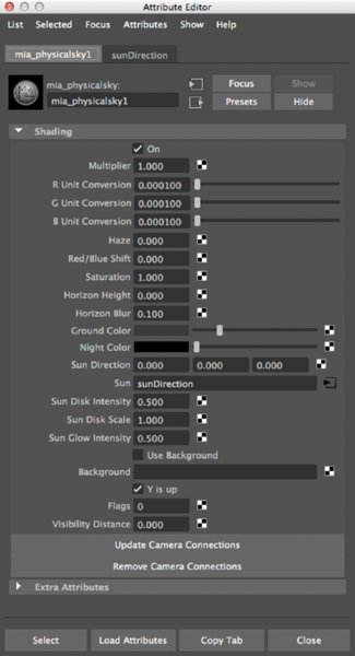
Figure 7.21 The settings for changing the look of the physical sky in the render
Multiplier This setting adjusts the overall brightness of the sky.
R, G, and B Unit Conversions These settings adjust the coloring of the sky in the R (red), G (green), and B (blue) channels when these values are changed incrementally.
Haze This setting adds haziness to the sky.
Red/Blue Shift Use this option to shift between warm and cool lighting in a scene. Negative numbers shift colors toward blue; positive numbers shift colors toward red. The value range should be kept between –1 and 1.
Saturation The saturation is physically accurate at a value of 1.0. Changing the value to 0.0 removes the color values, causing a grayscale image. Increasing it to its maximum value of 2.0 raises the color intensities.
Horizon Height and Blur These settings change the position and blurriness of the horizon line visible in the renders behind the geometry.
Ground Color This option changes the color of the area below the horizon. Note that the horizon does appear in reflective shaders applied to the geometry in the scene.
Night Color This option affects the color of the sky when the sun is rotated close to 180 degrees.
Sun Direction This setting rotates the sunDirection light in the scene to change the sun direction. Fields should be left at 0.
Sun This option connects the sun settings to a different light in the scene.
Sun Disk Intensity, Sun Disk Scale, and Sun Glow Intensity These settings affect the look of the sun when it is visible in the render.
Use Background This option adds a texture for the environment background. Use this setting as opposed to the standard Maya environment shaders.
Y Is Up Defines which axis points to up in the world. When unchecked, the sun and sky are oriented to Z up.
Flags This parameter is for internal testing and should always be set to 0.
Visibility Distance Defines the distance at which the haze effect becomes hazier.
Update Camera Connections This button adds a new renderable camera to the scene after you create the Physical Sun and Sky network. The network applies specific shaders to all of the renderable cameras in the scene when it is first created. Any new cameras added to the scene will not have these connections enabled by default. Click this button each time you add a new camera to the scene.
Remove Camera Connections This option removes all cameras from the Physical Sun and Sky network.
If you need to delete the Physical Sun and Sky network from the scene, open the Render Settings window and click the Delete button for the Physical Sun And Sky attribute.
mental ray Area Lights
mental ray area lights are designed to create a simulation of light sources in the real world. Most lights in Maya emit light rays from an infinitely small point in space. In the real world, light sources are three-dimensional objects, such as a lightbulb or a window, that have a defined size.
Lighting a scene using standard lights, such as the point and spot lights, often requires additional fill lighting to compensate for the fact that these lights do not behave like real-world light sources. Area lights are designed as an alternative to this approach. A mental ray area light is essentially an array of spot lights. The array creates a 3D light source, which results in more realistic light behaviors, especially with regard to shadow casting. The downside is that area lights often take longer to render, so they are not always ideal for every situation.
Follow the steps in this exercise to understand how to use area lights in mental ray:
![]()
- Open the
hospitalRoom_v01.mascene from thechapter7scenesfolder at the book’s web page. - Create an area light (Create ➣ Lights ➣ Area Light). Position the light using the following settings:
- Translate X: –6.842
- Translate Y: 12.424
- Translate Z: –5.567
- Rotate X: –90
- Scale X: 1.32
- Scale Y: 2.736
- Scale Z: 4.639
- Open the Render Settings window, and set Render Using to mental ray.
- Open the Render View window, and create a test render from the renderCam camera.
-
Store the image in the render view.
The render looks very blown out and grainy. You can reduce the grainy quality by increasing the shadow rays used on the light. However, there is something important and potentially confusing that you should know about using a standard Maya area light with mental ray. The light as it stands right now is not actually taking advantage of mental ray area light properties. To make the light a true mental ray area light, you need to enable the Use Light Shape attribute under the mental ray rollout under the Area Light section. Until you enable this attribute, you’ll have a hard time getting the area light to look realistic.
- Open the Attribute Editor for areaLight1. Switch to the areaLightShape1 tab.
-
In the mental ray ➣ Area Light rollout, activate Use Light Shape and create another test render (see Figure 7.22).
The new render is less blown out, and the shadows are much softer (although still grainy).
Unlike standard Maya area lights, the scale of the light does not affect the intensity of mental ray area lights. To change the intensity, use the Intensity slider at the top of the Attribute Editor. The shape of the shadows cast by mental ray area lights is affected by the shape specified in the Type menu and the scale of the light.
To improve the quality of the shadows, increase the High Samples setting. The High Samples and Low Samples settings control the quality of the shadow in reflected surfaces. These can be left at a low value to improve render efficiency.
- Set Type to Sphere for the light shape, and increase High Samples to 32.
- Turn on the Visible option.
-
Create a test render, and compare the render to the previous versions (see Figure 7.23).
Area lights come with several different preset shapes. The Sphere type area light is similar to a point light, but instead of emitting light from an infinitely small point in space, it emits from a spherical volume, making it ideal for simulating light cast from things such as lightbulbs.
You can also create an area light that behaves like a spot light.
- Change the light Type to a rectangular to match the shape of the light fixture.
- Place an area light within each of the light fixtures in the ceiling. You can duplicate the area light and move the duplicate into a new position.
- Create another test render (see Figure 7.24).
- Save the scene as
hospitalRoom_v05.ma.

Figure 7.22 The mental ray area light is enabled when Use Light Shape is activated in the Attribute Editor.

Figure 7.23 The area light is visible in the render.

Figure 7.24 The shape of the spot light creates shadows based on the area light settings.
The light quality and shadow shape remain the same as in the previous renders. However, switching the light Type setting to Spot Light adds the penumbra shape you would expect from a spot light. This allows you to combine the properties of spot lights and mental ray area lights. The Visible option in the mental ray settings does not work when using a spot light as the original light.
To see a version of the scene, open the hospitalRoom_v05.ma scene from the chapter7scenes folder at the book’s web page.
Light Shaders
mental ray has a number of light shaders that can be applied to lights in a scene. The purpose of these shaders is to extend the capabilities of Maya lights to allow for more lighting options. When a mental ray shader is applied to a Maya light, specific attributes on the original light node are overridden. The light’s attributes can then be set using the controls on the light shader node.
Some shaders, such as the Mib_blackbody and Mib_cie_d shaders, are very simple. These two shaders translate the color of the light as a temperature specified in kelvin. Other shaders are more complex, providing a number of attributes that can be used in special circumstances.
This section will discuss some of the light shaders and how you can use them in Maya scenes.
Physical Light Shader
The Physical Light shader is a type of shadow-casting light that is used in combination with indirect lighting (Final Gathering, global illumination) to create more physically accurate light behavior. There are also certain materials, such as the mental ray Architectural (mia) materials, that are designed to work with physical lights (these materials are discussed in Chapter 8, “mental ray Shading Techniques”).
Physical lights always cast raytrace shadows, and the falloff rate for the light obeys the inverse square law, just like lights in the real world. This law states that the intensity of light is inversely proportional to the square of the distance from the source. Thus the light intensity decreases rapidly as the light travels from the source.
Physical lights are easy to set up and use. Once you are comfortable with them, consider using them whenever you use indirect lighting, such as Global Illumination and Final Gathering. This exercise will show you how to create a physical light. The scene has a number of area lights positioned to match the recessed lighting fixtures in the ceiling.
- Open the
hospitalRoom_v05.mascene from thechapter7scenesfolder at the book’s web page. - Select areaLight1 and open its Attribute Editor.
- Under mental ray, expand the Custom Shaders rollout and click the checkered box to the right of the Light Shader field.
- From the Create Render Node pop-up, select the MentalRay Lights heading under the mental ray section (see Figure 7.25).
-
Choose physical_light from the right panel to create a light shader. This connects the shader to the area light.
The attributes for the physical_light shader will open in the Attribute Editor. You’ll see the settings for the shader:
Color The Color setting controls the color and intensity of the light by adjusting the color values in the color swatch.
Cone The Cone setting is used when the Physical Light shader is applied to mental ray spot and area spot lights to define the cone angle and penumbra. Higher values create a softer penumbra.
Threshold The Threshold setting defines a minimum illumination value. When you increase the threshold, the lighting in the scene is contracted around the brighter areas, giving you more control over the precise areas of light in the scene. This can cause hard edges to appear around the edges of light cast by spot lights even after you adjust the Cone value.
Cosine Exponent Similar to the Cone setting, the Cosine Exponent attribute contracts the area of light cast when the shader is applied to mental ray area lights. As the value of Cosine Exponent increases, the light cast by the area light becomes more focused.
- Open the Hypershade.
- Switch to the Utilities tab. (If the tabs do not appear at the top of the Hypershade, choose Tabs ➣ Revert To Default Tabs, and click OK in any warning windows that pop up.)
- Select the arealight2 node in the Outliner, and open its Attribute Editor.
- MMB-drag the physicalLight1 shader from the Utilities section of the Hypershade to the Light Shader field in the mental ray section of areaLight2’s Attribute Editor. This means that both area lights are connected to the same physical light shader.
- Repeat step 9 to add the physical light shader to areaLight3 and areaLight4.
- Create a test render from the renderCam camera (see Figure 7.26).
-
Store the render in the Render View window.
The lighting looks too bright. To fix this, you’ll use the Color swatch value in physical_light1’s Attribute Editor. The default value for the light is 1000.
- Click the color swatch to open the Color Chooser window. Change the lower-right menu to HSV. Change the Value cell to 250.
- Create a new test render. The room is darker but the lighting looks a bit blown out, and it does not look as though the lights are accurately lighting the room (see Figure 7.27). You can fix this by applying a tone-mapping lens shader to the renderCam camera.
- Save the scene as
hospitalRoom_v06.ma.

Figure 7.25 Apply the Physical Light shader to spotLight1.

Figure 7.26 Render the scene using a physical light.

Figure 7.27 The physical light shader creates a blown-out look to the render.
To see a version of this scene, open hospitalRoom_v06.ma from the chapter7scenes folder at the book’s web page.
Tone Mapping
![]()
Rendering using physical lights often results in a very blown-out image. This is because computer monitors are unable to display the full range of luminance values created by physical lights. To correct this, you will want to color manage the final image.
- Continue with the scene from the previous section, or open the
hospitalRoom_v06.mascene from thechapter7scenesfolder at the book’s web page. - Create a test render, and store the image for comparison.
- Open Windows ➣ Settings/Preferences ➣ Preferences.
- Choose Color Management from the Settings section of the Categories menu.
- Enable Color Management. The default settings convert your rendered images or Rendering Space to linear Rec 709/sRGB. Save your preferences to apply the changes. Your image should update, and the blacks and whites of the image should look more balanced (see Figure 7.28).
- To save the image properly choose File ➣ Save Image. On the right side of the Save Image browser, choose Save Color Managed Image.
- Save the scene as
hospitalRoom_v07.ma.

Figure 7.28 The final image of the hospital room with color management turned on
To see a version of the scene, open the hospitalRoom_v07.ma scene from the chapter7scenes folder at the book’s web page.
Photometric Lights and Profiles
Photometric lights allow you to attach light profiles created by light manufacturers so that you can simulate specific lights in your scenes. These profiles are often available on light manufacturers’ websites. The profile itself is a text file in the IES format.
The profiles simulate the qualities of the light, such as falloff and the influence of the light fixture. A light profile can include the sconces and fixtures attached to the light itself. This is most helpful in creating accurate architectural renderings.
To use a photometric light, you can attach the mib_light_photometric shader to a point light and then attach the profile to the light using the Profile field in the shader’s attributes. You can also skip using the shader altogether and attach the IES profile directly to the point light in the Light Profile field available in point lights.
In many cases, you’ll need to adjust the shadows cast by lights using a profile to make them more realistic. Use raytrace shadows, and adjust the Shadow Rays and Light Radius values to improve the look of the shadows.
If you’d like to experiment using light profiles, you can download IES-format light profiles from www.lsi-industries.com/products/products-home.aspx. Browse to any of their lights, and you can download the IES photometrics.
![]()
The Bottom Line
Use shadow-casting lights. Lights can cast either depth map or raytrace shadows. Depth map shadows are created from an image projected from the shadow-casting light, which reads the depth information of the scene. Raytrace shadows are calculated by tracing rays from the light source to the rendering camera.
Master It Compare mental ray depth map shadows to raytrace shadows. Render the
crystalGlobe.mascene using soft raytrace shadows.
Render with global illumination. Global illumination simulates indirect lighting by emitting photons into a scene. Global illumination photons react with surfaces that have diffuse shaders. Global illumination works particularly well in indoor lighting situations.
Master It Render the
rotunda_v01.mascene, found in thechapter7scenesfolder at the book’s web page, using global illumination.
Render with Final Gathering. Final Gathering is another method for creating indirect lighting. Final Gathering points are shot into the scene from the rendering camera. Final Gathering includes color bleeding and ambient occlusion shadowing as part of the indirect lighting.
Master It Create a fluorescent lightbulb from geometry that can light a room.
Use image-based lighting. Image-based lighting (IBL) uses an image to create lighting in a scene. High dynamic range images (HDRIs) are usually the most effective source for IBL. There are three ways to render with IBL: Final Gathering, global illumination, and with the light shader. These can also be combined if needed.
Master It Render the bicycle scene using the Uffizi Gallery probe HDR image available at
http://ict.debevec.org/~debevec/Probes.
Render using the Physical Sun and Sky network. The Physical Sun and Sky network creates realistic sunlight that’s ideal for outdoor rendering.
Master It Render a short animation showing the street corner at different times of day.
Understand mental ray area lights. mental ray area lights are activated in the mental ray section of an area light’s shape node when the Use Light Shape option is enabled. mental ray area lights render realistic, soft raytrace shadows. The light created from mental ray area lights is emitted from a three-dimensional array of lights as opposed to an infinitely small point in space.
Master It Build a lamp model that realistically lights a scene using an area light.