
Chapter 8
mental ray Shading Techniques
A shader is a rendering node that defines the material qualities of a surface. When you apply a shading node to your modeled geometry, you use the shader’s settings to determine how the surface will look when it’s rendered. Will it appear as shiny plastic? Rusted metal? Human skin? The shader is the starting point for answering these questions. Shading networks are created when one or more nodes are connected to the channels of the shader node. These networks can range from simple to extremely complex. The nodes that are connected to shaders are referred to as textures. They can be image files created in other software packages or procedural (computer-generated) patterns, or they can be special nodes designed to create a particular effect.
The Autodesk® Maya® software comes with a number of shader nodes that act as starting points for creating various material qualities. The mental ray® plug-in also comes with its own special shader nodes that expand the library of available materials. Since the mental ray rendering plug-in is most often used to create professional images and animations, this book emphasizes mental ray techniques. You’ll learn how to use mental ray shaders to create realistic images.
In this chapter, you will learn to
- Understand shading concepts
- Apply reflection and refraction blur
- Understand mila shading layers
Shading Concepts
Shaders are sets of specified properties that define how a surface reacts to lighting in a scene. A mental ray material is a text file that contains a description of those properties organized in a way that the software understands. In Maya, the Hypershade provides you with a graphical user interface so that you can edit and connect shaders without writing or editing the text files themselves.
The terms shader and material are synonymous; you’ll see them used interchangeably throughout this book and the Maya interface. mental ray also uses shaders to determine properties for lights, cameras, and other types of render nodes. For example, special lens shaders are applied to cameras to create effects such as depth of field.
![]()
This section focuses on shaders applied to geometry to determine surface quality. Three key concepts that determine how a shader makes a surface react to light are diffusion, reflection, and refraction. Generally speaking, light rays are reflected or absorbed or pass through a surface. Diffusion and reflection are two ways in which light rays bounce off a surface and back into the environment. Refraction refers to how a light ray is bent as it passes through a transparent surface. This section reviews these three concepts as well as other fundamentals that are important to understand before you start working with the shaders in a scene.
Diffusion
Diffusion describes how a light ray is reflected off a rough surface. Think of light rays striking concrete. Concrete is a rough surface covered in tiny bumps and crevices. As a light ray hits the bumpy surface, it is reflected back into the environment at different angles, which diffuse the reflection of light across the surface (see Figure 8.1).

Figure 8.1 Light rays that hit a rough surface are reflected back into the environment at different angles, diffusing light across the surface.
You see the surface color of the concrete mixed with the color of the lighting, but you generally don’t see the reflected image of nearby objects. A sheet of paper, a painted wall, and clothing are examples of diffuse surfaces.
In standard Maya shaders, the amount of diffusion is controlled by using the Diffuse slider. As the value of the Diffuse slider is increased, the surface appears brighter because it is reflecting more light back into the environment.
Reflection
When a surface is perfectly smooth, light rays bounce off the surface and back into the environment. The angle at which they bounce off the surface is equivalent to the angle at which they strike the surface—this is the incidence angle. This type of reflection is known as a specular reflection. You can see the reflected image of surrounding objects on the surface of smooth, reflective objects. Mirrors, polished wood, and opaque liquids are examples of reflective surfaces. A specular highlight is a reflection of the light source on the surface of the object (see Figure 8.2).

Figure 8.2 Light rays that hit a smooth surface are reflected back into the environment at an angle equivalent to the incidence of the light angle.
Logically, smoother surfaces, or surfaces that have a specular reflectivity, are less diffuse. However, many surfaces are composed of layers (think of glossy paper) that have both diffuse and specular reflectivity.
A glossy reflection occurs when the surface is not perfectly smooth but not so rough as to diffuse the light rays completely. The reflected image on a surface is blurry and bumpy and otherwise imperfect. Glossy surfaces can represent those surfaces that fit between diffuse reflectivity and specular reflectivity.
Refraction
A transparent surface can change the direction of the light rays as they pass through the surface (see Figure 8.3). The bending of light rays can distort the image of objects on the other side of the surface. Think of an object placed behind a glass of water. The image of the object as you look through the glass of water is distorted relative to an unobstructed view of the object. Both the glass and the water in the glass bend the light rays as they pass through.

Figure 8.3 Refraction changes the direction of light rays as they pass through a transparent surface.
Shaders use a refractive index value to determine how refractions will be calculated. The refraction index is a value that describes the amount by which the speed of the light rays is reduced as it travels through a transparent medium, as compared to the speed of light as it travels through a vacuum. The reduction in speed is related to the angle in which the light rays are bent as they move through the material. A refraction index of 1 means that the light rays are not bent. Glass typically has a refractive index between 1.5 and 1.6; water has a refractive index of 1.33.
If the refracting surface has imperfections, this can further scatter the light rays as they pass through the surface. This creates a blurry refraction.
The controls for refraction are found in the Raytrace Options section of the Attribute Editor of standard Maya shaders. A shader must have some amount of transparency before refraction has any visible effect.
The Fresnel Effect
The Fresnel effect is named for the nineteenth-century French physicist Augustin-Jean Fresnel (pronounced with a silent s). This effect describes the amount of reflection and refraction that occurs on a surface as the viewing angle changes. The glancing angle is the angle at which you view a surface. If you are standing in front of a wall, the wall is perpendicular to your viewing angle, and thus the glancing angle is 0. If you are on the beach looking out across the ocean, the glancing angle of the surface of the water is very high. The Fresnel effect states that as the glancing angle increases, the surface becomes more reflective than refractive. It’s easy to see objects in water as you stare straight down into water (low glancing angle); however, as you stare across the surface of water, the reflectivity increases, and the reflection of the sky and the environment makes it increasingly difficult to see objects in the water.
Opaque, reflective objects also demonstrate this effect. As you look at a billiard ball, the environment is more easily seen reflected on the edges of the ball as they turn away from you than on the parts of the ball that are perpendicular to your view (see Figure 8.4).

Figure 8.4 A demonstration of the Fresnel effect on reflective surfaces: the reflectivity increases on the parts of the sphere that turn away from the camera.
Anisotropy
Anisotropic reflections appear on surfaces that have directionality to their roughness, which causes the reflection of light to spread in one direction more than another. When you look at the surface of a compact disc, you see the tiny grooves that are created when data is written to the disc to create the satin-like anisotropic reflections. Brushed metal, hair, and satin are all examples of materials that have anisotropic specular reflections.
The resulting stretch or compression of an anisotropic reflection is defined in U and V directions. Anisotropy works in conjunction with the UV coordinates defined on a piece of geometry. (UV texture layout will be covered in Chapter 9, “Texture Mapping”.)
Layering Shaders
![]()
Layering shaders allow you to create a shader with infinite complexity. Autodesk Maya 2016 offers mental ray’s latest layering library, which includes its mila (mental image layering) shaders. The layering shaders are separate components of a traditional shader divided into separate nodes that can easily be stacked and blended on top of one another. The basic rule for using layering shaders is this: If you don’t need it, don’t include it. For instance, if you are creating a shader for a brick wall, there is no need to include transparency settings.
Layering shaders are considered physical-based shaders. Therefore, they should interact only with lights that are physically plausible; that is, the light should act like a real-world light. Area lights and image-based lighting work best with the layering shaders, since their visible light corresponds with the light that they actually cast. Other lights can be used, but the results may not be desirable.
The base layering shader is the mila material. It is created and assigned to geometry, as would be any other shader. When you create the mila material, a layer node and diffuse material are created automatically (see Figure 8.5).
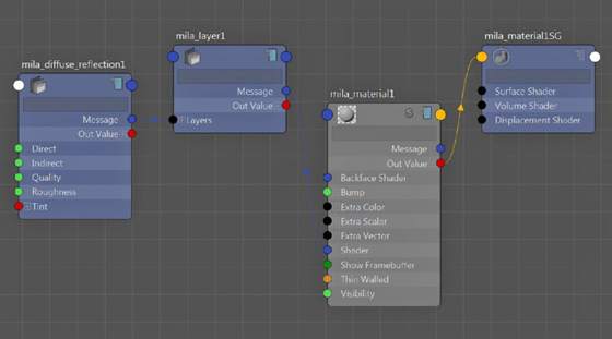
Figure 8.5 A graphed mila material in the Hypershade
From an artistic point of view, the mila material simply collects information from its layers. It does not contribute to the actual shading of the surface to which it’s assigned. With that, the mila material must always have a base component. By default, the base component is a diffuse layer. This is comparable to a Lambert shader. There are three variations of base components: diffuse, reflective, and transmissive or translucent (see Figure 8.6). You can change the base component at any time without affecting added layers.

Figure 8.6 Examples of each of the base components. From left to right: diffuse, reflective, and transmissive.
Layers are added from within the mila material. Each layer is weighted. Its effect over bottom layers can be reduced by decreasing the layer’s weight. After adding your first layer, you have the option to add a mix layer. Mix layers blend the layer components in an additive manner. For instance, mixing two diffuse layers, one red and one blue, would result in a purple diffuse shader.
A layer’s directional weight can be controlled through three different layer types: Weighted, Fresnel, or Custom. These options are available when you create a new layer. The directional weight of a layer controls how light interacts with that layer. Choosing a type sets specific options in the layer node. Weighted is the plain version of the layer without any directional weight. Fresnel uses the index of refraction (IOR) value established in the layer. Custom allows you to define your own normal and grazing reflectivity. Regardless of the type of layer you choose, you can always change the settings after the layer has been created, but the attributes will work only with the appropriate layer type.
You can add as many components as you want to a single layer. You can also create multiple layers and connect them to a single layer, combining the effects from every component. Layering shaders are extremely versatile and unrestricted. In the next chapter, you’ll create a layering network with subsurface scattering components to give a lifelike appearance to a giraffe model.
Creating Reflections and Refractions
Standard Maya shaders, such as the Blinn and Phong shaders, take advantage of mental ray reflection and refraction blurring to simulate realistic material behaviors. These options are available in the mental ray section of the shader’s Attribute Editor. However, turning these options on does not make the shader physically correct. They can also take a while to render. By using a mila shader, you can optimize your shading network and achieve a more realistic look.
Reflection
Reflection is easy to use, and it helps make objects look photo real. This exercise demonstrates how to add reflection and roughness to a surface using mila shaders. This scene contains a model of a coffeemaker above a checkered ground plane.
- Open the
reflections_v01.mafile from thechapter8scenesfolder at the book’s web page (www.sybex.com/go/masteringmaya2016). - In the Outliner, select the glass surface from the coffeePot hierarchy.
- Open the Hypershade window, and select Create ➢ mental ray Materials ➢ mila_material. Name the shader
mila_glass_MAT. - RMB over mila_glass_MAT, and choose Graph Network from the marking menu. The network is now exposed in the Node Editor panel.
- In the Material Viewer panel, change the renderer from Hardware to mental ray.
-
Under the Base rollout, in the Property Editor, choose black for the color.
- mila materials work in layers. Since you are creating glass, your next step is to add a layer of transparency. Choose the +Layer button from the Property Editor. A new window appears with three options. Choose Weighted Layer.
- Another window reveals a list of elemental components. Choose Transparency (see Figure 8.7).
- The shader is completely transparent. It’s time to add some reflectivity. Choose the +Layer button, and then add a Weighted Layer ➢ Specular Reflection component.
- The Material Viewer shows that your material is a mirror instead of reflective glass. Change the Weight value under the Specular Reflection rollout to 0.5. Figure 8.8 shows the rendered coffeepot.
- At this point, you have a clean reflective surface. To add a touch of blur and some highlights, add a Weighted Glossy Reflection.
- Change the Roughness to
0.2.The Roughness defines microscopic variations in the surface, causing the light that hits it to bounce off in different directions. Ultimately, this creates a blurring effect (see Figure 8.9). - Save the scene as
reflections_v02.ma.

Figure 8.7 Choose the Transparency component.

Figure 8.8 Add a Specular Reflection component to make the pot reflective.
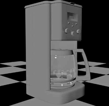
Figure 8.9 The reflection on the glass pot is blurred.
Many surfaces are more reflective than you may realize. An unpolished wooden tabletop, or even asphalt, can have a small amount of reflection. Adding a low reflectivity value plus reflection blurring to many surfaces increases the realism of the scene.
Refractions
Refractions cause the light passing through a surface to bend in different directions. The refraction component works just like the reflection component. Adding roughness causes microscopic variations in the surface. As a result, it can cause distortion and blurring of the objects that appear behind a transparent surface. The following exercise continues where the previous one left off.
- Open the
reflections_v02.mafile from thechapter8scenesfolder at the book’s web page (www.sybex.com/go/masteringmaya2016). - Select backSplash from within the coffeeMaker hierarchy, and assign the checker_MAT to it. Having a textured object behind your glass pot will help you determine how much of a blur effect to add.
- Select the mia_glass_MAT shader. Under the Property Editor panel in the Hypershade, choose the +Layer button and add a Weighted Glossy Transmission component.
- Set the Weight value to
0.7. - Change the Roughness to
0.7to increase the amount of blur. Figure 8.10 shows the results. - Light is not being refracted as expected. The reason for this is that you added a transparency component for the shader’s first layer in the previous exercise. Scroll to the Transparency layer in the Property Editor. Click the trashcan icon to delete the layer.
- Render the coffeepot again and you’ll see that the problem has been fixed. Light passing through the glass is now bent accordingly (see Figure 8.11).
- The effect of the refraction is too extreme. Reduce the Roughness to
0.2. The result is shown in Figure 8.12. - Save the scene as
refractions_v01.ma.

Figure 8.10 The refracted light causes the checkerboard texture to look brighter but not blurry.

Figure 8.11 With the Transparency component removed, light refraction renders correctly.

Figure 8.12 The glass pot renders physically correct, with reflections and refractions.
To see a version of the scene, open the refractions_v01.ma file from the chapter8scenes folder at the book’s web page.
![]()
Creating Metals and Plastics
In this exercise, you’ll work on defining materials for the coffeemaker. The chapter8
eference folder at the book’s web page contains a photo of the appliance to help you match the look. The example scene uses the Physical Sun and Sky lighting network and Final Gathering to light the scene.
- Open the
coffeeMaker_v01.mascene from thechapter8scenesfolder at the book’s web page. The surfaces in the model have been grouped to keep the model organized. - You’ll create a brushed aluminum shader first. Create a new mila_material, and name it
brushedAluminum_MAT. - In the Outliner, expand the coffeePot and coffeeMaker groups. Select silverRing, controlPanel, and backing. Apply the brushed aluminum material to the objects (right-click the material in the Hypershade, and choose Assign Material To Selection).
- Add a weighted Glossy Reflection component. Change the Weight to
1.0and the Roughness to0.3. Use an HSV Color value of0.6. - A render of the coffeemaker shows the aluminum texture. A brushed aluminum surface has special microscopic variations that affect its specular highlights. Instead of the typical rounded highlight shape, it tends to be elongated. Select mila_glossy_reflection2 by selecting the mila_layer2 tab from the Attribute Editor and clicking Go To Input Connection. Expand the Anisotropy rollout. Set Anisotropy to
0.1. - Create a test render. The Physical Sun and Sky setup automatically adds gamma to your render. To see the colors correctly, set your Color Management to Raw inside the Render View window under the View Transform drop-down menu (see Figure 8.13).

Figure 8.13 Apply the brushed aluminum shader to parts of the coffeemaker.
You can tweak many of the settings to create your own custom metal, but it already looks pretty good. Next, you can add a black plastic material to various parts of the coffeemaker:
- Create a new mila_material, and name it
shinyBlackPlastic_MAT. - Add a weighted Specular Reflection component. Change the Weight to
0.2and the layer’s Color toblack. - Select the following objects and assign the black plastic material:
- Backsplash
- Handle
- Knobs
- Lid
- Spout
- TopCasing
- Trim
- Base
- Create a test render to see the progress (see Figure 8.14).
- Save the scene as
coffeeMaker_v02.ma.

Figure 8.14 The black plastic material is applied to all of the plastic parts of the coffeemaker.
To see a version of the scene, open the coffeeMaker_v02.ma scene from the chapter8scenes folder at the book’s web page.
Adding Shaders to Individual Polygons
Some areas of the coffeemaker’s control panel are not brushed aluminum. Several polygon faces for the digital readout should have different shaders assigned to them. The following exercise demonstrates applying a shader to these areas:
- Open the
coffeeMaker_v02.mascene from thechapter8scenesfolder at the book’s web page. - Select the faces shown in Figure 8.15.
- RMB-click the shinyBlackPlastic_MAT shader, and choose Assign Material To Selection.
- Create a new mila material. Name it
readout_MAT. - Change the Base Color to match the following:
- H:
68.571 - S:
0.167 - V:
0.329
- H:
- Select the two faces inside the shiny black plastic area that you selected in step 1. Assign readout_MAT to the faces.
- Create a test render of the coffeemaker to see the new materials.
- Repeat the process and assign the brushed aluminum shader to the inner circle of the control knob. Figure 8.16 shows the rendered results.
- Save the scene as
coffeeMaker_v03.ma.

Figure 8.15 Select the faces surrounding the digital readout area.

Figure 8.16 Individual faces have been assigned to different shaders for parts of the coffeemaker.
To see a version of the scene, open the coffeeMaker_v03.ma scene from the chapter8scenes folder at the book’s web page.
Building a Layered Car Paint Shader
In reality, car paint consists of several layers; these layers combine to give the body of a car its special, sparkling quality. Car paint uses a base-color pigment, and the color of this pigment changes hue depending on the viewing angle. This color layer also has thousands of tiny flakes of metal suspended within it. When the sun reflects off these metallic flakes, you see a noticeable sparkling quality. Above these layers is a reflective clear coat, which is usually highly reflective (especially for new cars) and occasionally glossy. The clear coat itself is a perfect study in Fresnel reflections. As the surfaces of the car turn away from the viewing angle, the reflectivity of the surface increases.
In this section, you’ll learn how to use the car paint material by applying it to a model of a truck.
-
Open the
truck_v01.mascene from thechapter8scenesfolder at the book’s web page. This scene uses the Physical Sun and Sky network for lighting. - Open the Hypershade window, and select Create ➢ mental ray Materials ➢ mila_material.
- Open the mila_material shader’s Attribute Editor. Change the Base Component to Reflective (Paint) (see Figure 8.17).
- The truck has several shaders already applied. In the Materials tab in the Hypershade, RMB-click carParts1 and choose Select Objects With Material; this will select all of the polygons on the model that use this shader.
- Assign the mila_material shader created in step 3 to the selected parts. Parts of the truck body now appear red.
- Rename the mila_material shader to
carPaint1_MAT. - Select the faces of carParts2 shader, and assign carPaint1_MAT to it.
- Select
carPaint1_MATfrom the Hypershade. Choose the Input and Output Connections icon to graph the material’s connections in the Hypershade Node Editor (see Figure 8.18).

Figure 8.17 Use the Reflective (Paint) base component.

Figure 8.18 Graph the material to expose all of its connections in the Hypershade Node Editor.
Base Parameters
At the top of the attributes, you’ll find the Base rollout. The settings here determine the color properties of the base pigment layer. As the color of this layer changes depending on the viewing angle, the various settings determine all of the colors that contribute to this layer.
- Set the Color to a dark red. Choose the default pure red color swatch. Using the HSV color settings, change the value to
0.6. If you wanted to add a texture map to apply decals to the car, you would use this channel. Figure 8.19 shows a render of the truck so far. -
Set Edge Color to a similar shade of red, but lower the value so that it is almost black. Edge Color is apparent on the edges that face away from the camera. Newer cars and sports cars benefit from a dark Edge Color setting.
Edge Color Bias specifies the amount of spread seen in Edge Color. Lower values (0.1 to 3) create a wider spread; higher values (4 to 10) create a narrower band of Edge Color.
- Edge Weight controls the overall contribution of the edge color effect. Set this value to
10.0. Figure 8.20 shows the rendered results. - Glossy Color is the color seen in the surface areas that face the light source. Change the Glossy Color settings to match the following values:
- H:
360.0 - S:
0.421 - V:
0.348
- H:
- Use the following Flake settings:
- Flake Weight:
0.2 - Flake Scale:
0.001 - Flake Density:
0.4 - Flake Strength:
0.1
- Flake Weight:

Figure 8.19 A dark red tint has been added to the shader.

Figure 8.20 Increase the Edge Weight value to see the effect of the Edge Color setting.
You can see the rendered version with the new Flake settings in Figure 8.21.

Figure 8.21 The Flake parameters have been set.
Flake Parameters
The Flake Parameters settings are the most interesting components of the shader. These determine the look and intensity of the metallic flakes in the pigment layer of the car paint:
Flake Color Should usually be white for new cars.
Flake Weight A multiplier for Flake Color. Higher values intensify the look of the flakes; 1 is usually a good setting for most situations.
Flake Roughness Changes the shader from a typical Lambert-style shading at 0 to a more powdery look at 1.0.
Flake Scale Sets the size of the flakes. It’s important to understand that the size of the flakes is connected to the scale of the object. If you notice that the size of the flakes is different on one part of the car compared to the others, select the surface geometry and freeze the transformations so that the Scale X, Y, and Z values are all set to 1. This will correct the problem and ensure that the flakes are a consistent size across all of the parts of the car.
Flake Density Determines the number of flakes visible in the paint. The values range from 0.0 to 1.0. In many situations, a high value means that the individual flakes are harder to see.
Flake Strength Varies the orientation of the flakes in the paint. Setting this to 0 makes all of the flakes parallel to the surface; a setting of 1 causes the flakes to be oriented randomly, making the flakes more reflective at different viewing angles.
Flake Type Specifies different procedural patterns to define the shape of the flakes.
Flake Cell Style Forces the pattern specified in the Flake Type setting to be represented as irregular shapes or circles.
Flake Circle Size Increases or decreases the size of the circular pattern if Circular is chosen for the Flake Cell Style value.
Specular Reflection Layer
A specular layer defines the look of the specular highlight on the surface. By adding a specular layer, you can make the car paint look brand-new or old and dull.
- Select carParts1_MAT. In its Attribute Editor, choose the +Layer button.
- From the pop-up window, choose Fresnel Layer.
- From the next pop-up window, choose Specular Reflection.
- The layer is added to the mila_material shader. An abridged version of the specular reflection layer’s attributes is displayed within the material node. Change the Fresnel IOR attribute to
1.44to match the IOR of aluminum. Figure 8.22 shows the rendered results.

Figure 8.22 A specular reflection layer has been added.
Glossy Reflection Parameters
The reflectivity of the surface is at its maximum when Reflection Color is set to white. When this option is set to black, reflections are turned off.
- Select carParts1_MAT. In its Attribute Editor, choose the +Layer button.
- From the pop-up window, choose Fresnel Layer.
- From the next pop-up window, choose Glossy Reflection.
- The layer is added to the mila_material shader. Change the Fresnel IOR attribute to
1.44. - To mimic the crisp reflective proprieties of metal, change the Roughness setting to
0.0. Figure 8.23 shows the results of the glossy layer. - Add the carParts1_MAT to the rest of the vehicle’s parts.
- Save the scene as
truck_v02.ma.

Figure 8.23 A glossy reflection layer has been added.
To see a finished version of the scene, open the truck_v02.ma file from the chapter8scenes folder at the book’s web page.
The Bottom Line
Understand shading concepts. Light rays are reflected, absorbed by, or transmitted through a surface. A rough surface diffuses the reflection of light by bouncing light rays in nearly random directions. Specular reflections occur on smooth surfaces; the angle at which rays bounce off a smooth surface is equivalent to the angle at which they strike the surface. Refraction occurs when light rays are bent as they are transmitted through the surface. A specular highlight is the reflection of a light source on a surface. In CG rendering, this effect is often controlled separately from reflection; in the real world, specular reflection and highlights are intrinsically related.
Master It Make a standard Blinn shader appear like glass refracting light in the
jellybeans_v01.mascene in thechapter8scenesfolder on the book’s web page.
Apply reflection and refraction blur. Reflection and Refraction Blur are special mental ray options available on many standard Maya shading nodes. You can use these settings to create glossy reflections when rendering standard Maya shading nodes with mental ray.
Master It Create the look of translucent plastic using a standard Maya Blinn shader.
Understand mila shading layers. The layering shaders are separate components of a traditional shader that can easily be stacked and blended on top of one another. Layered shaders allow you to add an infinite amount of detail to a single shader.
Master It Create a mix layer and blend two colored diffuse layers together.