
Chapter 14
Hair and Clothing
The Autodesk® Maya® software offers a number of tools for adding fur, hair, and clothing to characters. Creative use of these tools adds believability and originality to your animated characters. In addition, many of these tools can be used to create engaging visual effects.
In this chapter, you will learn to
- Add XGen descriptions to characters
- Create dynamic curves
- Add hair to characters
- Style hair
- Paint nCloth properties
Understanding XGen
XGen is an arbitrary primitive generator. With XGen, you can place any number of primitive objects in a scene. Regardless of the type of object you use, XGen gives you the ability to control attributes such as size and shape. Using XGen, you can create grass, hair, or even an entire forest.
XGen works by creating primitives. A primitive can be a spline, sphere, card, or archive. (An archive is a polygon object that has been saved previously.) Primitives cannot be manipulated individually. Instead, you control primitives through guides, attributes, and expressions. This allows you to make changes to thousands, or even millions of primitives at once. Figure 14.1 shows the window used for controlling XGen.

Figure 14.1 XGen has a separate window for creating and controlling its components.
There are four major components to XGen:
Descriptions These are the core of any XGen endeavor. A description is used to define everything about the look of the primitive. Multiple descriptions can be added to a polygon surface. They can also be saved and reused on different objects.
Patches Patches are attached to polygon faces, and they let the description know where and how to place the primitives. Patches are identified with a magenta X that is placed in the center of the polygon face to which it is connected. There are no attributes that you can modify in a patch.
Collections Descriptions are always placed within a collection, and collections are used to organize your descriptions. They create external folders in your project directory to keep the numerous associated description files from conflicting with other descriptions.
Guides Guides are representations of what your primitive objects will look like. Some guides can be selected and shaped. Shaping the guide is preferable when dealing with long hair.
XGen uses Ptex texture maps to store attribute information about your description. Most importantly, it uses Ptex texture maps to place your primitives on a polygon surface. As a result, your geometry does not need UVs to work with an XGen description.
Creating an XGen Description
The first step in using XGen is to create a description. Descriptions can be added to polygon surfaces or selected faces. In this exercise, you’ll build a description to define hair for a character’s head.
- Open the
hairstyle_v01.mascene from thechapter14scenesfolder at the book’s web page,www.sybex.com/go/masteringmaya2016. - Select all of the faces of the character’s scalp. Use Figure 14.2 as reference.
- With the faces selected, choose Generate ➣ XGen Editor in the Modeling menu set. Alternatively, you could choose Generate ➣ Create Description to go directly to the creation options. You will need to work in the XGen Editor, so it makes sense to open it.
- In the XGen Editor, click Create New Description.
- Name the description shortHair, and create a new collection named female. Refer to Figure 14.3 for the rest of the settings.
- The Grooming Tools tab is automatically selected because of the description you chose. Under the Settings rollout, increase the Density parameter to increase the number of groomable guides. Set Density to 50.0 (see Figure 14.4).
- When you’re creating a hairstyle, it’s best to start with the length. You can always increase or decrease the length as you work, but starting with the longest length mimics the way a hairstyle is cut in the real world. In the Settings rollout, change Length to 1.6 to increase the length of the hair uniformly.
- Choose the Length brush from the Brush rollout. To paint length, you first establish a goal length. In this case, you want to trim the length of the hair. By default, the goal is set to 5.0 cm. Change Goal Length to 0.5. This value now represents the shortest possible length of hair. Set the Increment to –0.1 to cut the hair’s length gradually. Paint the sideburns area to shorten the hair length.
- Choose the Smooth brush. Paint the transitional area between the two different lengths of hair that you painted in step 8. The Smooth brush changes the hair length to make a gradual transition (see Figure 14.5).
- Under the Edit rollout, choose Flip To Right to mirror the changes that you made to the other side of the head.
- Choose the Pose brush, which is a combination of the Orient and Bend brushes. Posing the hair is a bit like brushing and curling your hair at the same time. Use the brush to comb half of the hair down. At this point, you need to comb only one side of the character’s head (see Figure 14.6).
- Choose Flip To Right to mirror the combed hair to the other side of the character’s head. You can mirror your changes as often as needed.
- With the hair flattened to the character’s head, you can begin to see problems with the hair’s length. Choose the Length brush and trim along the sides to taper the length.
- Use the Smooth brush to even out the length of the hair. If you find that you cut too much, switch to the Length brush. Increase the Goal Length value and flip Increment from negative to positive to extend the hair’s length.
- Use the Pose brush to style the hair. Start at the root of the hair and drag the brush in the direction that you want the hair to go.
- The hair guides do not automatically detect the surface underneath it. If hairs are pushed below the scalp surface, use the Elevation brush to lift them back up. Remember that you can mirror your changes to the other side of the character’s head at any time.
- The Attract brush pulls hairs toward the brush. This can give the effect of wet or gelled hair. Use the Attract brush to create several clumped areas to give the haircut some style (see Figure 14.7). Use a small brush size to avoid clumping too many hairs together.
- Hair is never perfect. Adding noise increases the realism of any hair design. Select the Noise brush. Increase the Middle attribute to 0.2 to disrupt the position of the hair from its root to its middle. Increase the Tip value to 0.435. Apply the brush sparingly to the character’s hair (see Figure 14.8).
- Save the scene as
hairstyle_v02.ma.

Figure 14.2 Select faces for the character’s scalp.

Figure 14.3 The settings for creating a new description

Figure 14.4 Additional guides are added to the description based on the Density parameter.

Figure 14.5 The Smooth brush can be used to soften the transition between hair attributes.

Figure 14.6 Use the Pose brush like a comb to style and shape the hair.

Figure 14.7 Use the Attract brush to create clumps of hair.
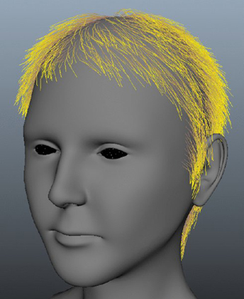
Figure 14.8 Add noise to give the hair a more realistic appearance.
To see a version of the scene, open the hairstyle_v02.ma scene from the chapter14scenes folder.
XGen Library
![]()
The XGen Library allows you to store hair and fur presets into an organized window. It works by creating an .xgp file, which is a text document that contains the settings specific to your preset. Maya stores the preset and its corresponding files in a library folder under the Maya install directory. You can, however, create your own folder and add its path to the XGen Library. You can access the library from the Generate drop-down menu. Figure 14.9 shows the XGen Library window.

Figure 14.9 The XGen Library window
Maya 2016 comes with numerous preset descriptions in the XGen Library. These descriptions are a valuable resource from which you can start a new description or to analyze the preset’s properties to learn different techniques. Figure 14.9 shows the included presets.
Adding a preset to your geometry is a simple task. The following steps take you through the process:
- Select your geometry or individual faces to which you want to assign the XGen preset.
- Double-click the desired preset.
- The Import Preset window is displayed. You can add your preset to an existing collection or create a new one (see Figure 14.10).
- Choose Import to apply the preset. The preset itself does not change or modify an existing description. Instead, it adds a new description. Based on this, you can layer different descriptions onto the same geometry. Figure 14.11 combines the Calico_Cat and Dreadlocks descriptions.

Figure 14.10 The Import Preset window

Figure 14.11 Two different descriptions have been combined onto a single polygon face selection.
Rendering an XGen Description
![]()
When a description is created, Maya automatically assigns a mental ray® xgen_hair_physical shader based on Marschner’s hair shading technique. You can view the shader in Viewport 2.0 to see both color and lighting effects. Before visualizing the shader, you want to make sure that you have enough primitives to render. The next exercise takes you through the steps to render your character’s hairstyle:
- Continue with your scene or open the
hairstyle_v02.mascene from thechapter14scenesfolder. - In the toolbar of the XGen window is an eyeball icon. Below the eyeball is a triangle with an exclamation mark. The icon is the preview button for displaying your primitives. Click the button to force XGen to update the primitives to match your groomed guides.
-
The eyeball icon or preview button changes, and a check appears under the eye. You will also notice that primitive splines now cover the character’s head (see Figure 14.12).
The splines match the guide’s shape and position. However, they do not match the width. Under the Settings rollout, change Width to 0.01. Click the Preview button to see your changes.
-
Zoom in close to a few primitive strands of hair. The splines are tubular. Their start width is the same as their end width. To taper the hair, choose the Primitives tab. Under the Primitives Attributes rollout, set Taper to 0.7 and Taper Start to 0.5. Update the preview to see the results (see Figure 14.13).

- Choose the Grooming tab. Under the Settings rollout, deselect Visibility to turn off the guides. The hair looks pretty sparse. You can increase the density of your primitives through the Density attribute since Sync is checked. However, at this point, any additional hairs will be added with default settings. This means that the new hairs will not be groomed like the old hairs. To prevent this, choose Interp from the Sampling attribute.
- Change Density to 400. The hairs are blended with the existing groomed hairs.
- Render a version of the hair. Figure 14.14 shows the result.
- Select XGen_hair_phen from the Hypershade, and open its Attribute Editor. Change Diffuse Color to match the following settings:
- Hue: 46.347
- Saturation: 0.388
- Value: 1.0
- Set Indirect Diffuse Mode to On in the render settings, and turn off the Default light. Change the Background Color setting (under the perspective camera’s Environment rollout) to a sky blue. Add a back light and render the scene (see Figure 14.15).

Figure 14.12 Primitive splines are added among the guides.

Figure 14.13 Taper the width of the primitive splines.

Figure 14.14 A render of the current state of the hair

Figure 14.15 The hair is colored, lit, and rendered.
To see a version of the scene, open the hairstyle_v03.ma scene from the chapter14scenes folder. To learn more about XGen, you can watch the movies in the chapter14movies folder.
Animating Using Dynamic Curves
Dynamic curves are NURBS curves driven by the Nucleus dynamic simulation framework. The primary use of dynamic curves is to drive the dynamics of nHair systems applied to characters. They can also be used to drive fur. However, the usefulness of dynamic curves goes far beyond creating hair motion. Curves used to loft or extrude surfaces, curves used for Paint Effects strokes, curves projected on NURBS surfaces, curves used as IK splines, curves used as particle emitters, and so on, can be made dynamic, thus opening up a large number of possibilities for creating additional dynamic effects in Maya. While working through the scenes in this chapter, you may want to set the timeline preferences to loop so that you can see the hair update continuously as you adjust its settings. In addition, with all simulation, make sure to set the Playback Speed to Play every frame. To do so, follow these steps:
- Choose Windows ➣ Settings/Preferences ➣ Preferences.
- Choose the Time Slider category in the Preferences dialog box.
- Set Looping to Continuous.
- Expand the Playback speed rollout and choose Play Every Frame.
Using Dynamic Curves with IK Splines
In Chapter 5, “Rigging and Muscle Systems,” you learned about the IK Spline tool, which uses a curve to control the inverse kinematics (IK) of a joint chain. The curve itself can be converted into a dynamic curve that can be used to drive the IK Spline tool. This is a great way to add dynamic motion to a rig used for tails or tentacles.
In this example, you’ll use a dynamic curve to control a segmented armored tail. The armored tail consists of polygon pieces, each of which has been parent-constrained to a joint in a chain. The first step is to create a curve (see Figure 14.16).
- Open the
armoredTail_v01.mascene from thechapter14scenesfolder at the book’s web page. - Switch to a side view, and select Snap To Points.
- In the viewport’s Show menu, turn off the visibility of polygons so that only the joints are visible.
- Choose Create ➣ Curve Tools ➣ EP Curve Tool. Click the first joint in the chain on the far-left side and the last joint in the chain on the far-right side.
-
Press Enter to complete the curve.
The EP Curve tool creates a curve that has four CVs. Using the EP Curve tool is an easy way to create a straight curve. If you want to add more vertices, you can use the Curves ➣ Rebuild command. In the options, specify how many spans you want to add to the curve. In this example, the curve should work fine with only four CVs.
- Switch to the perspective view. Turn off the visibility of Joints in the Show menu so that only the curve is visible.
-
Switch to the FX menu set. Select curve1, and choose nHair ➣ Make Selected Curves Dynamic. In the Outliner, a new hairSystem1 node is created, as are two groups: hairSystem1Follicles and hairSystem1OutputCurves (see Figure 14.17).
- Set the timeline to 200, and click the Play button. You’ll see the dynamic curve move a little. (It can be a little hard to see; this will be more obvious in the next step.)
- Stop the playback, and select the hairSystemShape1 tab in the hairSystem1’s Attribute Editor.
-
In the Stiffness Scale rollout panel under Dynamic Properties, set the Selected value to 0 and play the scene. You’ll see the dynamic curve droop a little. As the scene is playing, set the Stretch Resistance value under the Dynamic Properties rollout to 0.1.
The Stiffness setting controls the rigidity of the curve. A higher Stiffness setting makes the curve less flexible. Lowering the Stiffness value makes the curve bend easily.
As you decrease the Stretch Resistance value, the curve stretches as much as it needs to in order to accommodate the dynamic forces applied to the curve. You’ll notice the curve droop downward, indicating that it has weight. The Nucleus solver controls the gravity, as discussed in Chapter 12, “Introducing nParticles.”
You’ll notice that both ends of the curve appear to be attached to the original curve (see Figure 14.18).
- Stop the playback, and rewind the animation.
- Set the Selected Value under the Stiffness Scale rollout to 1.0 and Bend Resistance under the Dynamic Properties rollout to 0.5.
- Select the follicle1 node in the Outliner, and switch to the Move tool (turn off Snap To Grids or Snap To Points if it is still on).
- In the FX menu set, choose Fields/Solvers ➣ Interactive Playback. The animation starts playing automatically. As it is playing, move the follicle around in the scene; you’ll see the dynamic curve follow the movements.
- Stop the animation, and switch to the follicleShape1 tab in the Attribute Editor.
-
Under the Follicle Attributes rollout, set Point Lock to Base. Choose Interactive Playback, and move the follicle around again. Interactive Playback will continue until the simulation reaches end of the timeline. You’ll see that the dynamic curve is attached at only one end.
If you wanted the curve to be attached to the other end, you’d set Point Lock to Tip. To detach the curve entirely, set Point Lock to No Attach.
- Stop the animation, and rewind the playback.
- Select the follicle1 node, and set the Translate channels to 0 to return the curve to its start position.
- With the follicle selected, select Snap To Points.
- Hold the d key, and use the Move tool to move the pivot point of the follicle to the end of the curve on the side where the dynamic curve is still attached, as shown in Figure 14.19.
- When the pivot point is repositioned, Shift+click the Translate and Rotate channels in the Channel Box, right-click, and choose Key Selected from the pop-up context menu.
-
Select Auto Keyframe; go to various points in the animation, and move and rotate the follicle.
While Auto Keyframe is selected, a keyframe is placed on all of the Translate and Rotate channels as you make changes to the position of the follicle. The dynamic curve may not update correctly as you make changes; don’t worry about that at the moment.
You want to create an animation where the curve moves around in the scene like a sword slashing through the air.
- Rewind and play the animation; you’ll see the dynamic curve follow the movements of the follicle as it moves through the air.
- Save the scene as
armoredTail_v02.ma.

Figure 14.16 The armored tail consists of polygon pieces constrained to a joint chain.

Figure 14.17 The dynamic curve droops as if it is attached at both ends to the original curve.

Figure 14.18 A number of nodes are added to the scene when a curve is made dynamic.

Figure 14.19 Move the pivot point of the follicle to the end of the curve.
To see a version of the scene, open the armoredTail_v02.ma scene from the chapter14scenes folder.
Creating an IK Spline Handle from the Dynamic Curve
In this section, you’ll create an IK spline handle for the armored tail and attach it to the dynamic curve. The dynamics of the curve will be edited to change the behavior of the tail.
- Continue with the scene from the previous section, or open the
armoredTail_v02.mascene from thechapter14scenesfolder. - In the perspective view, turn on the visibility of joints in the Show menu.
- In the Outliner, select and hide the follicle1 node. This prevents you from selecting the wrong curve when creating the IK spline handle.
- Switch to the Rigging menu set, and choose Skeleton ➣ Create IK Spline Handle ➣ ❒.
- In the Tool Settings dialog box, make sure that Auto Create Curve and Root On Curve are both deselected.
- With the IK Spline Handle tool active, select the first joint in the chain and the last joint in the chain.
-
Zoom in closely, and carefully select the blue curve that runs down the center of the chain.
If the operation is successful, you’ll see the ikHandle1 node appear in the Outliner. The Dynamic curve (curve4) will move out of the hairSystem1OutputCurves group. That should not affect how the curve behaves.
- Rewind and play the scene. The joints follow the motion of the curves.
- In the Show menu of the perspective view, turn the visibility of polygons back on and play the scene. The armored tail thrashes around when you play the animation.
- In the Outliner, select the hairSystem node and open its Attribute Editor to the hairSystemShape tab.
-
Expand the Dynamic Properties and Stiffness Scale sections.
The Stiffness Scale edit curve changes the stiffness of the curve along the length of the curve. The left side of the curve corresponds to the stiffness at the base; the right side of the curve corresponds to the stiffness at the tip.
- Add a point to the Stiffness Scale edit curve by clicking the left side of the curve and dragging downward.
- Play the animation, and you’ll see the end of the tail lag behind the motion more than the front of the tail. You should be able to edit the curve while the animation is playing and observe the changes (see Figure 14.20).
- Save the scene as
armoredTail_v03.ma.

Figure 14.20 Editing the Stiffness Scale curve changes the stiffness along the length of the dynamic hair.
The Stiffness setting creates the overall stiffness value for the dynamic curve. Stiffness Scale modifies that value along the length of the curve. Both settings, like almost all of the dynamic curve settings, can be animated.
To see a version of the scene, open the armoredTail_v03.ma file from the chapter14scenes folder.
Using Forces
The settings in the Forces section add levels of control for the curve’s motion. Play the animation in the armoredTail_v03.ma scene, and adjust these settings while the scene loops so that you can see how they affect the motion of the tail.
Mass Affects the motion of the curve only when additional fields (created from the FX menu set) are applied to the curve—for example, a Turbulence or a Drag field. Mass does not change how the curve responds to forces created in the hairSystem1 shape node. Increasing Mass increases the simulated weight of each CV on the curve as the curve moves through a dynamic field.
Drag Creates friction between the dynamic curve and the air. Increasing this value is a good way to simulate the motion of hair in thick fluids.
Tangential Drag Applies a resistance along the direction of the hair curve shape. Increasing this value is also a good way to simulate the motion of hair in thick fluids.
Motion Drag Similar to Drag. However, Motion Drag is affected by the Stiffness Scale attribute. In other words, the Drag setting creates a drag in the motion across the length of the dynamic curve, whereas Motion Drag creates a drag along the length of the curve that is influenced by the Stiffness Scale curve. This setting can be used to fine-tune the motion of the dynamic curve.
Damp Used most often to control erratic motion of dynamic curves. Higher Damp values decrease the momentum of the curve as it follows the motion of the follicle.
Stretch Damp Used most often to control erratic motion of dynamic curves. Higher Damp values decrease the momentum of the curve as it follows the motion of the follicle.
Dynamics Weight Controls the amount of overall influence external dynamic fields (such as Turbulence and Drag) have over the dynamic curve. It does not influence how the Forces settings in the hairSystem node affect the dynamic curve.
Adding Hair to a Character
Maya offers two methods for adding hair to a character, XGen and nHair. If you plan on animating the hair, you will have to connect your XGen guides to an nHair system. This section focuses on using nHair to build a head of hair. To learn how to use XGen for creating hair, watch the movies in the chapter14movies folder. You should complete this section before creating XGen hair.
Hair is created by attaching follicle nodes to a surface. Each follicle node controls a number of hairs. The follicles themselves are styled using a combination of control curves and forces. Follicles and control curves are connected to a hair system node. A single hair system node can control hair connected to any number of surfaces, and a single surface can be attached to multiple hair systems.
When you create hair, you have to consider how you plan to render it. You have the choice of creating Paint Effects strokes for the hair or curves that can be used to render in third-party engines such as Pixar’s RenderMan® or creating both Paint Effects strokes and curves. Even though hair uses Paint Effects, it renders using mental ray without the need to convert the hair to polygons.
Applying Hair to a Surface
When you want to apply hair to a character, you can either apply the hair uniformly to the entire surface or paint the hair selectively on parts of the surface.
It is common practice to create a nonrendering scalp surface that can be parented to a character’s head and then apply the hair to the scalp surface rather than directly to the character’s head. This approach allows flexibility because scalp surfaces and their attached hair can easily be swapped between characters. It also speeds up playback in the animation because the hair dynamics are not factored into the calculations required to deform the character’s surface if it has been skinned to a skeleton or to other deformers.
Some animators like to apply separate hair systems to each part of the scalp to control the various sections of a particular hairstyle. For instance, one hair system may be applied to the bangs that hang over the character’s forehead, whereas another system may be used for the hair on the back of the head. In this exercise, you’ll keep things simple by using a single hair system for the character’s hairstyle. Both methods are valid, and as you become comfortable working with hair, you may want to experiment with different techniques to see which approach works best for you.
The following procedure uses a rigged character head. The head is rigged to a series of joints. You can select and rotate the headCtrl curves above the head to change the position of the head. A scalp surface has been created by duplicating part of the head geometry. This scalp geometry is parent-constrained to one of the joints in the head rig.
You can apply hair to NURBS or polygon surfaces. When you use polygon surfaces, the UV texture coordinates must be mapped so that none of the UVs overlap and the coordinates fit within the 0 to 1 range in the UV Texture Editor. As with fur, you’ll get better results from your hair system if the UV coordinates have been carefully mapped. Remember to delete history for the surface once you have created UV texture coordinates to keep the coordinates (and attached hair) from moving unpredictably during animation.
- Open the
nancyHair_v01.mascene from thechapter14scenesfolder. - In the Outliner, select the scalp surface and open its Attribute Editor.
-
In the scalpShape tab, expand the Render Stats section; then deselect Casts Shadows, Receive Shadows, Motion Blur, and Primary Visibility so that the surface will not render or affect any other geometry in the render.
For the scalp, you’ll create a simple grid and then add follicles if needed later.
- Make sure that the scalp surface is selected, switch to the FX menu set, and choose nHair ➣ Create Hair ➣ ❒.
- In the Create Hair Options dialog box, choose Edit ➣ Reset Settings to reset the options to the default settings.
- Set the Output to Paint Effects, and choose the Grid option. Use the following settings:
- U and V Count: 24
- Passive Fill: 0
- Randomization: 0.1
-
Select the Edge Bounded and Equalize options.
When the Grid method is used, the follicles are placed uniformly on the surface based on the U and V coordinates. If Edge Bounded is on, the follicles are placed up to and including the edge of the UV coordinates. In the case of the example, this means that hairs are placed along the edge of the scalp surface. The Equalize option evens out the spacing of the follicle placement to compensate for areas of the U and V coordinates that may be stretched or squashed.
-
Set Points Per Hair to 20 and Length to 5.
Hairs that have more points per curve are more flexible and have more detail in their motion as they respond to dynamics; they also slow down the playback speed of Maya in the scene. The Length attribute can be modified after creation.
The Place Hairs Into option should be set to New Hair System. If a hair system exists in the scene already, you can use this option to add the newly created hairs into the existing system by selecting it from the list. Figure 14.21 shows the settings for the new hair.
- Click Create Hairs to make the hair. The hairs appear as long spikes coming out of the head (see Figure 14.22).
- Select the nancy head geometry. Choose nCloth ➣ Create Passive Collider.
- Click Play, and the hairs start to fall. After a few moments, the hairs start to settle.
- Save the scene as
nancyHair_v02.ma.

Figure 14.21 The Create Hair Options area

Figure 14.22 The hairs appear as long spikes on the top of the head. When you click the Play button, the hairs fall and settle into a basic hair shape.
To see a version of the scene, open the nancyHair_v02.ma scene from the chapter14scenes folder.
In the next section, you’ll learn how to style the hair.
Determining Hair Shape
A number of settings in the hair system node determine the look of the hair. These are found in the Clump and Hair Shape section of the hair system’s attributes.
- Continue with your scene or open the
nancyHair_v03.mascene from thechapter14scenesfolder. - Select hairSystem1, and open its Attribute Editor to the hairSystemShape1 tab.
- The hair appears as groups bunched around long spikes that shoot out from the scalp. Each group of hairs is a clump. The movement of each clump of hair is driven by the movement of the follicles. This way, Maya can create dynamics for thousands of hairs using a much smaller number of follicles. The hair remains as long spikes until you play the simulation and let the hair fall down. For the moment, leave the animation at frame 1. It’s easier to see how the clumps work when the hair is in its spiky state. In the Clump and Hair Shape section, increase the Hairs Per Clump number to 60 to increase the fullness of the hair.
- Play the animation until frame 20, and then stop the animation.
-
Zoom in to the end of a clump, and move the Bend Follow slider back and forth.
When Bend Follow is at 0, the end of the clump appears flat if the follicle is curved. When Bend Follow is 1, the clump shape is more tubular toward the end of the clump. This attribute should be used to fine-tune the look of your hair as you develop the overall shape.
-
Rewind the animation, and set Clump Width to 0.7. This expands the overall width of the clumps, which helps fill out the hairstyle without the need to add more follicles.
In the Clump and Hair Shape rollout, you can use the following settings to determine the look of the hair:
Baldness Map The Baldness Map field allows you to apply a texture to control where the hair grows on the head. The texture must be a black-and-white 2D texture. The texture itself does not need to be baked as it does with fur. Just like with fur, black areas of the map indicate no hair (or baldness), and white areas indicate places where the hair grows. Texture maps can also be used, much like the texture maps created for fur baldness.
Sub Segments Use this setting to improve the details of the hair (such as curls and kinks) when rendered. Increasing this setting does not affect the dynamics of the hair.
Thinning Higher values decrease the number of hairs per clump to create a thin and wispy look to the hair.
Clump Twist This setting rotates each clump around the base of the follicle. Positive values rotate the clump in one direction; negative values rotate it in the opposite direction. Twisting the clump rotates all of the hairs uniformly. If you like the way the hair looks on one side of the clump, you can use the clump twist to rotate the preferred side toward the camera.
Bend Follow This setting determines how closely the rotation of the clump affects the shape of the hair clumps. This is most noticeable at the end of each clump.
Hair Width Hair Width adjusts the width of the hairs. This setting can be used to thicken or thin the hair. The effect of changing hair width is seen when the hair is rendered. This is a setting you’ll probably want to return to when you are setting up your hair for a render.
Below the Clump and Hair Shape setting sliders are a number of edit curves that can be used to further refine the hair shape. The left side of each curve represents the area of the clump closest to the root; the right side represents the area closest to the tip. Each scale uses the setting in the sliders in the Clump And Hair Shape section as a starting point, so each scale is a modifier for the settings that you have already created. The following describes how each ramp affects the look of the hair:
Clump and Hair Width Scale You can exaggerate or reduce the amount of tapering in the clumps by changing the Clump Width Scale edit curve. Hair Width Scale modifies the width of the hairs based on the setting in the Hair Width slider.
Clump Curl The Clump Curl edit curve can be used to twist the clumps around the central axis of the follicle. By default, the graph is set so that the value of the curling is at 0.5. By moving a point on the curve up or down (moving up creates values closer to 1; moving down creates values closer to 0), the curling twists in one direction or the other (see Figure 14.23).
Clump Flatness The Clump Flatness scale can be used to make the clumps appear as flat planks of hair. Higher values along the curve flatten out the clumps. This setting works well for creating the shape of wet hair.
The final two settings in this section are sliders labeled Clump Interpolation and Interpolation Range:
Clump Interpolation Increasing the Clump Interpolation slider spreads the hair out between clumps. This slider can be used to even out the shape of the hair so that the clumping is much less obvious. Dynamics are calculated based on the position of each clump. If you set a high Clump Interpolation value, you may find that hairs do not appear to collide correctly. This is because the interpolation can push hairs outside the boundary of the original clump width, and thus their placement exceeds the collision width of their clump.
Interpolation Range Interpolation Range sets the limits for how far a hair can move out of the width of the clump when Clump Interpolation is increased. The value set in Interpolation Range is multiplied against the Clump Width setting.
- Play the animation to frame 50 and stop.
- Remove any extra points that you may have placed on the Clump Width Scale and Clump Curl so that there are only two points on the scales—one on the far right and one on the far left.
- Set the value of the point on the left side of the Clump Width Scale to 1; set the point on the far right to 0.32.
- Set the point on the far right of the Clump Curl curve to 0.6.
- Set the point on the far left of the Clump Flatness scale to 0.5. Add a point to the far right side of Clump Flatness, and move it to 0.7. This helps the roots of the hair to lie closer to the head, creating less of a “poufy” shape.
- Set Clump Interpolation to 0.3. Leave Interpolation Range set to the default value of 8.
- Rewind and play the animation, and make any changes you’d like to the shape of the hair. The length, color, and other properties are further defined in the next section. Rewind and play the animation.
- Save the scene as
nancyHair_v03.ma.

Figure 14.23 Adding and moving points along the various edit curves can shape the overall look of the hair.
To see a version of the scene, open the nancyHair_v03.ma scene from the chapter14/scenes folder.
Styling Hair
Once the hair has been set up, you can use a number of tools to style it. You can use dynamic fields as a hair-styling tool, paint follicle properties on the hair, or even manipulate the CVs of control curves.
Start and Rest Positions
Before styling the hair properly, you should create a start position for the hair so that the animation does not start with the hair sticking straight out of the head. Doing so makes styling much easier.
The start position represents the shape of the hair at the start of the simulation. The rest position represents the hair’s shape when no forces are acting upon it. These are very similar, but you can distinguish between the two by thinking of it like this: Imagine an animation where a character is jumping up and down and then stops. The animation starts with the character in midair. You want to set the start position to represent what the hair looks like when the character is in midair. Once the character stops jumping and the hair settles, the hair assumes its rest position. For some animations, the start and rest positions may look exactly the same; at other times, such as in the example described, the start and rest positions look different.
- Continue using the scene from the previous section, or open the
nancyHair_v03.mascene from thechapter14scenesfolder. - Play the animation until the hair has completely settled (see Figure 14.24).
- Once the hair has settled, expand the hairSystem1Follicles group in the Outliner and Shift+click all of the follicle nodes.
- Choose nHair ➣ Set Start Position ➣ From Current.
- Set the rest position by choosing nHair ➣ Set Rest Position ➣ From Current.
-
Rewind the animation. The hair should now be down and relatively motionless at the start of the animation.
The start and rest positions are determined by two sets of curves that drive the follicles. You can activate the visibility of these curves in the Perspective window.
- In the Viewport menu, use the Show menu to turn off the visibility of Strokes. This hides the Paint Effects hair.
- Select the hairSystem1 node, and choose nHair ➣ Display ➣ Start Position. A series of curves appears in blue, representing the hair’s start position.
- Choose nHair ➣ Display ➣ Rest Position. The rest position curves appear in red. If the start and rest positions for the hair system are different, each set of curves will have a different shape.
- Choose nHair ➣ Display ➣ Start Position. Save the scene as
nancyHair_v04.ma.

Figure 14.24 Run the simulation to get the hair to settle around the head.
To see a version of the scene, open the nancyHair_v04.ma scene from the chapter14scenes folder at the book’s web page.
Painting Follicle Attributes
Using the Artisan Brush interface, you can paint follicle attributes. Before doing this, you must make sure that the hair is in its rest or start position. Some attributes, such as Inclination, require that the animation be on frame1.
- Continue with the scene from the previous section, or open the
nancyHair_v04.mascene from thechapter14scenesfolder. - Select the hairSystem1 node or the scalp surface.
-
From the FX menu set, choose nHair ➣ Paint Hair Follicles ➣ ❒.
The Tool Options area for the Artisan Brush interface opens as well as the Paint Hair Follicles Settings pop-up box.
-
Set Paint Mode to Trim Hairs. This setting allows you to reduce the length of the hair as you paint across the follicles.
For the dynamics to remain consistent, you must adjust the number of points on the hair as you paint. When you created the hair originally, the Points Per Hair attribute was set to 10, so to trim the length of a hair by half, set Points Per Hair to 5. The Points Per Hair setting determines how the hair will be trimmed. When you set Points Per Hair to 5, the hair will be trimmed to half the original length regardless of the Hair Length setting.
- Set Points Per Hair to 5, and paint across the follicles in the front of the scalp to create bangs for the nancy character (see Figure 14.25).
- Once you have trimmed the hair, select the follicles in the Outliner (it’s easiest just to Shift+click all of the follicles rather than figure out which ones were painted), and choose nHair ➣ Set Rest Position ➣ From Current.
-
To extend the hair, set Paint Mode to Extend Hairs, and increase Points Per Hair to a number larger than 10. Remember to reset the rest and start positions after extending the hair.
You can use the nHair ➣ Scale Hair Tool to apply global scaling to the hair. To use this tool, select it from the nHair menu and drag left or right. This tool will scale all aspects of the hair, so some adjustment to the shape and dynamics settings may be required after using the tool.
To paint other attributes, set Paint Mode to Edit Follicle Attributes and choose an attribute from the Follicle Attribute menu. When painting these attributes, the Value setting in the Paint Attributes area of the Artisan Brush interface determines the value painted on the follicles.
- Save the scene as
nancyHair_v05.ma.

Figure 14.25 Trim the hair at the front of the head using the Paint Hair Follicles tool.
To see a version of the scene, open the nancyHair_v05.ma scene from the chapter14scenes folder.
Modifying Curves
You can modify curves directly by moving their CVs or by using the tools in the nHair ➣ Modify Curves menu. By modifying curves directly, you can fine-tune a style.
You can modify only start or rest curves. To do this, use the Show menu in the viewport window to disable the visibility of strokes in the scene, and choose nHair ➣ Display ➣ Rest Position (or Start Position). Select the curve (or right-click the curve and choose Control Vertex to work just on selected CVs), and apply one of the actions listed in the nHair ➣ Modify Curves menu. You can also edit the shape of the curve directly using the Move tool to change the position of CVs on the curve (see Figure 14.26).

Figure 14.26 Modify the CVs of a start curve using the Move tool.
As you are editing the curve, you can lock the length so that the changes you make do not stretch the curve beyond its original length. Select the curve, and choose nHair ➣ Modify Curves ➣ Lock Length (or use the l hot key). Conversely, you can unlock the curve if you want to change its length.
Curling, Noise, Sub Clumping, and Braids
Curling, Noise, and Braids all work best when the Sub Segments attribute in the Clump and Hair Shape section of the hair system node is increased. You can find the Curl and Noise settings in the Displacements section of the hairSystemShape node.
The Sub Clumping setting causes the hair within clumps to bunch together. This helps when you are creating wet or kinky hair.
The Braid option is available as an attribute for individual hair follicle nodes. It is located on the follicleShape node under the Follicle Attributes rollout. For a braid to work successfully, you may need to alter the clump shape and the Hairs Per Clump. It may be a good idea to use a separate hair system to create a detailed braid.
Rendering Hair
Rendering hair can be done using Maya Software or mental ray. The hair should be either Paint Effects strokes or Paint Effects strokes converted to geometry. Paint Effects strokes are discussed in detail in Chapter 10, “Paint Effects.”
Rendering hair is a straightforward process. If you’re not familiar with Paint Effects, you should review Chapter 10 before reading this section.
When you convert hair to geometry, the Hair Tube shader is automatically applied. You can render Paint Effects hair using mental ray without the need to convert the hair to geometry.
When you are ready to render the hair, you’ll want to increase the hair’s Sub Segments setting in the hairSystemShape tab, as well as Hairs Per Clump, Hair Width, and Hair Width Scale, in order to create fuller hair. You can always add follicles as well using the Paint Follicles tool.
In the Render Stats section of the hairSystemShape tab, you can enable Receive Shadows, Visible In Reflections, and Visible In Refractions when rendering with mental ray. If the hair will not render using mental ray, make sure that the Render Fur/Hair checkbox is selected on the Diagnostics tab in the mental ray Render Settings.
In this scene, the dreads.mel preset, found on the Hair Examples tab of the Visor, is applied to the nancy model. The hairLights.mel file has also been imported from the Visor and applied to the scene.
- Open the
renderHair.mascene from thechapter14scenesfolder at the book’s web page. - Switch to the quarterSide camera, and create a test render in the Render View window.
The scene is set up to render using mental ray. The render will take a couple of minutes. Figure 14.27 shows the results (shadows have been enabled for the lights in the image).

Figure 14.27 Apply the dreadlocks preset hair to the nancy model, and render it with mental ray.
Most standard lights will render hair nicely. When you’re testing the look of the hair, using the hairLights.mel preset makes it easy to see how the hair will look when rendered.
Creating Clothing for Characters
In this section, you’ll explore techniques for using nCloth to add dynamic motion to a character’s clothes. The example files are simple, but you can use the same techniques for more complex characters and models.
The Nucleus solver divides its computations into multiple threads for self-colliding surfaces and stretch resistance. Additional threading is also used to speed up playback of simulations with multiple nCloth objects on the same solver. Before starting this section, you should review Chapter 12 (“Introducing nParticles”) and Chapter 13 (“Dynamic Effects”) so that you understand how nDynamics and the Nucleus solver work.
Modeling Clothes for nCloth
The models that you create for use with nCloth must be polygon meshes. Beyond that, there is nothing special about how you model your clothing. Smooth mesh polygons work just as well as standard polygons. You’ll start by taking a look at an example scene.
This scene has a simple cartoon character that has been rigged and animated. The character has a shirt and pants that have been created using standard polygon modeling techniques. Both objects are currently smooth mesh polygons. The scene has been arranged so that the display layers contain the major components of the model and the animation rig.
- Open the
simpleMan_v01.mascene from thechapter14scenesfolder at the book’s web page (see Figure 14.28). - Switch to the FX menu set.
- Select the pants, and choose nCloth ➣ Create nCloth. The pants switch to standard polygon mode.
- Select the pants, and press the 3 key to switch to smooth mesh polygons.
- Play the scene. You’ll see the pants fall down. (This kind of thing can be embarrassing, but it happens a lot to cartoon characters; see Figure 14.29.)

Figure 14.28 The simpleMan_v01.ma scene contains a simple cartoon character. Clothes have been modeled using polygons.

Figure 14.29 When you play the scene, the character’s pants fall down.
The first step in preventing the pants from falling is to make the character’s body a Passive Collider object. It does not matter that the character is already rigged and animated. However, it’s a good idea to convert the polygons to nCloth objects (both nCloth and Passive Collider objects) when the character is in the default pose and there are no intersections between the nCloth and Passive Collider geometry.
- Rewind the animation.
- In the Display Layer Editor, click the R next to the MAN layer to turn off Reference mode so that you can directly select the man geometry.
- Select the man geometry, and choose nCloth ➣ Create Passive Collider.
- Make sure that you are starting at frame 0, and play the scene. The pants still fall down, but the character’s feet stop them from falling indefinitely.
- Save the scene as
simpleMan_v02.ma.
To see a version of the scene, open the simpleMan_v02.ma scene from the chapter14scenes folder.
In the next section, you’ll create a constraint that will keep a character’s pants from falling down.
Using Constraints
The simplest way to keep the character’s pants on is to create a transform constraint. A transform constraint attaches the selected vertices on an nCloth object to the pivot point of another object without affecting the position of the nCloth vertices. When the constraining object is translated or rotated, the vertices follow along, dragging the rest of the nCloth object with them.
- Continue with the scene from the previous section, or open the
simpleMan_v02.mascene from thechapter14scenesfolder at the book’s web page. - Right-click the pants, and choose Vertex to switch to vertex selection mode.
- Select a single vertex along the top row of the pants. Double-click the next vertex in the row in order to select the entire vertex loop.
- With the vertices selected (they should be highlighted in yellow), Shift-click the man geometry and choose nConstraint ➣ Point to Surface. The vertices should turn green, indicating that they are constrained. In the Outliner, you’ll see that a new dynamicConstraint1 node has been created (see Figure 14.30).
- Play the animation. The pants should now stay in place, and when the man starts moving, they should collide with the character’s legs.
- Save the scene as
simpleMan_v03.ma.

Figure 14.30 Select the vertices at the top of the pants. When you constrain the vertices to the body, the pants stay up and collide with the animated character.
To see a version of the scene, open the simpleMan_v03.ma scene from the chapter14scenes folder at the book’s web page.
You can also constrain objects to components of nCloth objects, such as vertices. Using this technique, you can easily simulate the effect of buttons holding a shirt together.
- Continue with the scene from the previous section, or open the
simpleMan_v03.mascene from thechapter14scenesfolder. - In the Display Layer Editor, turn on the visibility of the SHIRT layer.
- Before converting the shirt to an nCloth object, make sure that it does not intersect with the pants. Rotate the view so that you can see the back of the character; here you can see that the shirt is intersecting the pants (see Figure 14.31).
- Right-click the faces near the intersection, and choose Faces.
- Use the Move tool to move the faces outward just enough so that they do not intersect the pants.
- Select the shirt, and choose nCloth ➣ Create nCloth. The shirt switches back to standard polygon mode; select the shirt, and press the 3 key to return to smooth mesh.
- Rewind and play the animation. The shirt falls until it collides with the character geometry. It moves as the character moves; however, you can see the front of the shirt fly open (see Figure 14.32).
- Zoom in to the front of the shirt, and turn off the visibility of the MAN and PANTS display layers.
- Right-click the shirt, and choose Vertex.
- Switch to wireframe mode. Select the two vertices at the top of the shirt close to the collar (see Figure 14.33).
- Choose nConstraint ➣ Component To Component. This creates a constraint between the two vertices.
- Repeat steps 10 and 11 to create constraints for the other three pairs of vertices running down the shirt. You don’t need to constrain the two at the very bottom. You should end up with four constraints running down the front of the shirt.
- Switch to shaded mode, turn on the MAN and PANTS layers, and rewind and play the scene. The front of the shirt is now bound as if it has buttons (see Figure 14.34).
- Save the scene as
simpleMan_v04.ma.

Figure 14.31 The surface of the shirt intersects the pants in the back of the character. Use the Move tool to move the faces of the shirt outward to fix the problem.

Figure 14.32 As the character moves, the front of the shirt flies open.

Figure 14.33 Select vertices near the collar, and turn them into a constraint.

Figure 14.34 When you play the animation, the shirt stays closed as if it has buttons.
To see a version of the scene, open the simpleMan_v04.ma scene from the chapter14scenes folder at the book’s web page.
The Component constraint differs from the Component To Component constraint that you just used; you can use it to replace nCloth’s internal Stretch constraints. As a result, you gain a high level of individual control. The following steps demonstrate the process and the potential for the Component constraint:
- Continue with the scene from the previous section, or open the
simpleMan_v04.mascene from thechapter14scenesfolder. - Select all of the vertices of the man’s shirt except for his sleeves (see Figure 14.35).
- Open the tool options for nConstraint ➣ Component. Make sure that you are using the defaults by resetting the tool. Click Apply to add the constraint (see Figure 14.36).
-
The Component constraint now controls the stretch values of the edges. Open the nCloth’s Attribute Editor. Under the Dynamic Properties section, set the Stretch Resistance value to 0.0.
Click the Play button to see the effects. The shirt holds together well where the constraint was added, but the sleeves slink down with gravity since they have no stretch resistance (see Figure 14.37).
- Return to frame 1. Select the two end loops of vertices from each sleeve, and choose nConstraint ➣ Component. The same options from step 3 are applied.
- Click the Play button to see the effects of the two constraints. Compare these to how the simulation worked without them. The sleeves are allowed to stretch more since there are no cross links holding back the garment’s ability to stretch. There is no need to save the scene file to continue.

Figure 14.35 Select the vertices of the shirt minus the sleeves.

Figure 14.36 The default attributes of the Component constraint

Figure 14.37 Without any resistance, the sleeves stretch with gravity.
Connecting Buttons to the Shirt
You can connect buttons to the shirt geometry using the Point On Poly constraint:
- Continue with the scene from the previous section, or open the
simpleMan_v04.mascene from thechapter14scenesfolder at the book’s web page. - In the Outliner, select button1. The button is located at the origin, so currently it is in the center of the character. Use the Move tool to move the button close to the top of the shirt. Enter the following settings:
- Translate X: 0.115
- Translate Y: 3.576
- Translate Z: 2.295
- Right-click the shirt geometry, and choose Vertex to switch to vertex selection mode.
- Select one of the vertices toward the top of the shirt on the inside edge (see Figure 14.38). Shift+click the button1 node.
- Switch to the Animation menu set, and choose Constrain ➣ Point On Poly. The button will snap to the geometry. Most likely, the position and the rotation will be off.
- In the Outliner, select the button1 object, expand it, and select the button1_pointOnPolyConstraint1 node.
- Open the Channel Box, and MMB-drag the field for Offset Rotate X to rotate the button to a better position; try a value of 75. You can use the other Offset fields to fine-tune the rotation and position of the button (see Figure 14.39).
- Repeat the process to constrain the other three buttons in the Outliner to the shirt.
- Save the scene as
simpleMan_v05.ma.

Figure 14.38 Select the vertices toward the top of the shirt, and then Shift+click the button.

Figure 14.39 The Offset fields are used to rotate and translate the constrained button into the correct position.
To see a version of the scene, open the simpleMan_v05.ma scene from the chapter14scenes folder at the book’s web page.
You can also select a face of a polygon object and use the Point On Poly constraint to attach an object to a polygon face.
Applying Forces
You can use wind or a directional force to move an nCloth object. You can assign these locally, affecting the object and leaving all other nCloth objects unaffected. This feature can be useful to give elements such as capes a cinematic feel. The settings to modify a local force or local wind are located on the nCloth shape node (see Figure 14.40).

Figure 14.40 The Local Force and Local Wind settings
Painting nCloth Properties
nCloth properties can be painted to gain detail in your simulation. You can paint properties such as Bounce, Stretch, and Wrinkle onto an nCloth object. All of the properties can be painted as vertex maps or texture maps.
When you paint a vertex property map, you paint property values directly onto the vertices of the object, similar to painting smooth skin weights for joints. The more vertices that you have in your object, the more detail that you can create for your vertex property map. The vertex map values are saved with the object, so you do not need to link to external map files.
Texture property maps are independent of the number of vertices in the object, but they do require that UVs are properly created for the object, meaning that the UVs do not overlap and do remain within the 0 to 1 range in the UV Texture Editor. Texture property maps for nCloth objects are similar to texture property maps created for fur. However, you do not need to bake the maps after applying them.
When you paint a vertex or texture map, the map is listed in the Attribute field in the Dynamic Properties section of the nCloth shape node’s Attribute Editor.
In this example, you’ll paint Wrinkle attributes for the simple man character’s pants. A wrinkle map displaces an nCloth object to create folds in the surface. You can paint detailed wrinkles into objects with a lot of vertices. In this example, you’ll use the wrinkle map to add cartoonish embellishments to the pants, which have a fairly low number of vertices.
When applying a Wrinkle attribute, positive values push the nCloth outward, while negative values push it inward. There are a few peculiarities about painting Wrinkle values, which you’ll explore in this exercise:
- Continue with the scene from the previous section, or open the
simpleMan_v05.mascene from thechapter14scenesfolder. - Turn off the visibility of the SHIRT and JOINTS layers.
- Rewind and play the animation. The pants maintain their shape until they start to collide.
-
Rewind the animation again; select the pants object, and from the FX menu set, choose nCloth ➣ Paint Vertex Properties ➣ Wrinkle ➣ ❒.
The pants turn white, indicating that a value of 1 is applied to the vertices of the pants for the Wrinkle property. Make sure that the Renderer in the Viewport menu is set to Legacy Default Viewport so that you can see the color values painted onto the pants geometry.
-
Rewind and play the animation. The pants suddenly bloat outward even though you have not made any changes (see Figure 14.41). What just happened?
When you start to create the wrinkle map, Maya applies a value of 1 to all of the vertices of the object at the moment the map is created. Prior to creating the wrinkle map, no Wrinkle value is applied to the pants, so they do not bloat outward until the map is made. This behavior is specific to the wrinkle map.
- In the Tool Settings dialog box, set the value to 0. Make sure that the Paint Attribute setting in the nCloth Attributes rollout panel of the Tool settings is set to Wrinkle.
-
Click the Flood button, and rewind the animation.
The pants turn black, and the bloating disappears. The wrinkle values are now set to 0 for all of the vertices of the pants geometry
At this point, you’ll paint the area where the pant legs emerge from the pants with a value of -0.2 so that the pant legs shrink inward. Notice, however, that the Value slider in the Artisan Tool options goes only from 0 to 1.
-
In the Tool Settings dialog box, look at the Min/Max value fields. Set the first field, which is the Min Value, to -1, and the second field, which is the Max Value, to 1.
Now it is possible to paint negative numbers, but you’ll notice that since the black color on the pants indicates a value of 0, there is no color feedback for negative numbers. This can be changed as well.
-
Scroll down to the bottom of the Tool Settings dialog box, and expand the Display rollout panel. Make sure that Color Feedback is on. Set Min Color to -1 and Max Color to 1 (see Figure 14.42).
The pants turn gray, indicating that the current value applied to the vertices (0) is in the middle range of colors between black and white. As you paint negative values on the pants, you’ll see darker areas appear.
- Set the Value slider to -0.2, and paint around the area where the pant legs meet the pants.
- Rewind and play the scene. You’ll see the tops of the pant legs shrink in a little.
- To create flares (flares on shorts are apparently all the rage now), set the value to 0.4, and paint the cuffs of the pants (see Figure 14.43).
- To create the impression of a drawstring, paint a value of -1 around the area of the pants where a belt would go.
- Press the q hot key to switch to the Select tool. Doing so will close the Artisan tool; the pants return to green.
- Rewind and play the animation. Experiment making more changes by painting various Wrinkle values on the pants.
- Save the scene as
simpleMan_v06.ma.
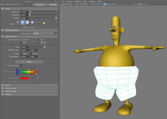
Figure 14.41 When you create the wrinkle map and play the animation, the pants bloat outward. When you apply the value 0 to all of the vertices, the pants turn black and the shape returns to normal.

Figure 14.42 You can adjust the Min/Max value fields to allow for a wider range of values for the Paint nCloth Attributes tool. Adjusting the Min Color and Max Color sliders lets you visualize the new values painted on the surface.

Figure 14.43 Paint a value of -0.2 around the belt area of the pants. Paint positive values near the pant cuffs to create flares.
To see a version of the scene, open the simpleMan_v06.ma scene from the chapter14scenes folder.
To learn more about fur, hair, and nCloth, check out Maya Studio Projects: Photorealistic Characters (Sybex, 2011).
The Bottom Line
Add XGen descriptions to characters. XGen is a primitive generator that adds realistic short hairs to the surface of character. The placement, length, and other attributes of the hairs can be controlled by painting on the surface using the XGen grooming tools.
Master It Create eyebrows for the head used at the beginning of this chapter.
Create dynamic curves. A standard Maya curve can be made dynamic by using the Make Dynamic Curves action in the Hair menu. A copy of the curve is created that will respond to dynamic motion and forces. The curve can be used in skeletons for IK Spline tools, as a source for Paint Effects strokes, as a modeling tool, or for any other effect that requires curves.
Master It Create a flag using dynamic curves.
Add hair to characters. Hair is created using Paint Effects strokes that are controlled by follicles. The follicles are dynamic curves that respond to forces and movement. Follicles can be applied to polygon or NURBS surfaces as a grid or by painting on the surface. The Visor contains a number of hair presets that can be imported into a scene.
Master It Add hair to the top of the giraffe’s head from Chapter 9.
Style hair. Hair can be styled by painting attribute values on follicles or by directly editing the CVs of start or rest curves.
Master It Create an avant-garde hairdo for the nancy character by painting attributes.
Paint nCloth properties. Properties such as Bounce, Stretch, and Wrinkle can be painted onto nCloth objects using either texture or vertex painting techniques. When painting properties, you may need to alter the Min and Max Value ranges in the Artisan interface to allow for values beyond the range of 0 to 1. Vertex maps have the advantage that the values are not stored in an external texture file.
Master It Add starch to the simple man’s shirt by painting a Rigidity value on the shirt geometry.