
10
Echo Cancellation
Giovanni Cherubini
10.2 Echo Cancellation for Pulse–Amplitude Modulation Systems
10.3 Echo Cancellation for Quadrature Amplitude Modulation Systems
10.4 Echo Cancellation for Orthogonal Frequency Division Multiplexing Systems
10.1 Introduction
Full-duplex data transmission over a single twisted-pair cable permits the simultaneous flow of information in two directions when the same frequency band is used. Examples of applications of this technique are found in digital communications systems that operate over the telephone network. In a digital subscriber loop, at each end of the full-duplex link, a circuit, known as hybrid, separates the two directions of transmission. To avoid signal reflections at the near- and far-end hybrid, a precise knowledge of the line impedance would be required. Since the line impedance depends on line parameters that, in general, are not exactly known, an attenuated and distorted replica of the transmit signal leaks to the receiver input as an echo signal. Data-driven adaptive echo cancellation mitigates the effects of impedance mismatch.
A similar problem is caused by crosstalk in transmission systems over voice-grade unshielded twisted-pair cables for local-area network applications, where multipair cables are used to physically separate the two directions of transmission. Crosstalk is a statistical phenomenon due to randomly varying differential capacitive and inductive coupling between adjacent two-wire transmission lines. At the rates of several megabits per second that are usually considered for local-area network applications, near-end crosstalk (NEXT) represents the predominant disturbance; hence, adaptive NEXT cancellation must be performed to ensure reliable communications.
In voiceband data modems, the model for the echo channel differs considerably from the echo model adopted in baseband transmission. The transmitted signal is a passband signal obtained by quadrature amplitude modulation (QAM), and the far-end echo may exhibit significant carrier-phase jitter and carrier-frequency shift, which are caused by signal processing at intermediate points in the telephone network. Therefore, a digital adaptive echo canceller for voiceband modems needs to embody algorithms that account for the presence of such additional impairments.
In this chapter, we describe the echo channel models and adaptive echo canceller structures that are obtained for various digital communications systems, which are classified according to the modulation techniques employed. We also address the trade-offs between complexity, speed of adaptation, and accuracy of cancellation in adaptive echo cancellers.
10.2 Echo Cancellation for Pulse–Amplitude Modulation Systems
The model of a full-duplex baseband data transmission system employing pulse–amplitude modulation (PAM) and adaptive echo cancellation is shown in Figure 10.1. To describe system operations, we consider one end of the full-duplex link. The configuration of an echo canceller for a PAM transmission system is shown in Figure 10.2. The transmitted data consist of a sequence {an} of independent and identically distributed (i.i.d.) real-valued symbols from the M-ary alphabet . The sequence {an} is converted into an analog signal by a digital-to-analog (D/A) converter. The conversion to a staircase signal by a zero-order hold D/A converter is described by the frequency response HD/A(f) = T sin(πfT)/(πfT), where T is the modulation interval. The D/A converter output is filtered by the analog transmit filter and is input to the channel through the hybrid.
The signal x(t) at the output of the low-pass analog receive filter has three components, namely, the signal from the far-end transmitter r(t), the echo u(t), and additive Gaussian noise w(t). The signal x(t) is given by
where is the sequence of symbols from the remote transmitter, and h(t) and hE(t) = {hD/A ⊗ gE}(t) are the impulse responses of the overall channel and the echo channel, respectively. In the expression of hE(t), the function hD/A(t) is the inverse Fourier transform of HD/A(f), and the operator ⊗ denotes convolution. The signal obtained after echo cancellation is processed by a detector that outputs the sequence of estimated symbols . In the case of full-duplex PAM data transmission over multipair cables for local-area network applications, where NEXT represents the main disturbance, the configuration of a digital NEXT canceller is obtained from Figure 10.2, with the echo channel replaced by the crosstalk channel. For these applications, however, instead of mono-duplex transmission, where one pair is used to transmit only in one direction and the other pair to transmit only in the reverse direction, dual-duplex transmission may be adopted. Bidirectional transmission at rate ρ over two pairs is then accomplished by full-duplex transmission of data streams at rate ρ/2 over each of the two pairs. The lower modulation rate and/or spectral efficiency required per pair for achieving an aggregate rate equal to ρ represents an advantage of dual-duplex over mono-duplex transmission. Dual-duplex transmission requires two transmitters and two receivers at each end of a link, as well as separation of the simultaneously transmitted and received signals on each pair, as illustrated in Figure 10.3. In dual-duplex transceivers, it is therefore necessary to suppress echoes returning from the hybrids and impedance discontinuities in the cable, as well as self NEXT, by adaptive digital echo and NEXT cancellation [2]. Although a dual-duplex scheme might appear to require higher implementation complexity than a mono-duplex scheme, it turns out that the two schemes are equivalent in terms of the number of multiply-and-add operations per second needed to perform the various filtering operations.

FIGURE 10.1 Model of a full-duplex PAM transmission system.

FIGURE 10.2 Configuration of an echo canceller for a PAM transmission system.
One of the transceivers in a full-duplex link will usually employ an externally provided reference clock for its transmit and receive operations. The other transceiver will extract timing from the received signal, and use this timing for its transmitter operations. This is known as loop timing, also illustrated in Figure 10.3. If signals were transmitted in opposite directions with independent clocks, signals received from the remote transmitter would generally shift in phase relative to the also-received echo signals. To cope with this effect, some form of interpolation would be required that can significantly increase the transceiver complexity [4].
In general, we consider baseband signaling techniques such that the signal at the output of the overall channel has nonnegligible excess bandwidth, that is, nonnegligible spectral components at frequencies larger than half of the modulation rate, |f| ≥ 1/2T. Therefore, to avoid aliasing, the signal x(t) is sampled at twice the modulation rate or at a higher sampling rate. Assuming a sampling rate equal to m/T, m > 1, the ith sample during the nth modulation interval is given by
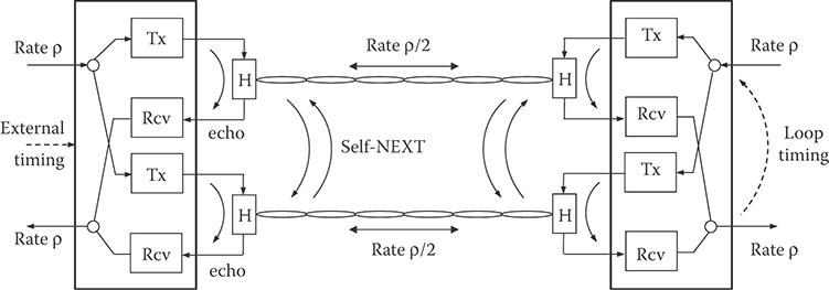
FIGURE 10.3 Model of a dual-duplex transmission system.
where {hnm+i, i = 0, …, m – 1} and {hE,nm+i, i = 0, …, m – 1} are the discrete-time impulse responses of the overall channel and the echo channel, respectively, and {wnm+i, i = 0, …, m – 1} is a sequence of Gaussian noise samples with zero mean and variance . Equation 10.2 suggests that the sequence of samples {xnm+i, i = 0, …, m – 1} be regarded as a set of m interleaved sequences, each with a sampling rate equal to the modulation rate. Similarly, the sequence of echo samples {unm+i, i = 0, …, m – 1} can be regarded as a set of m interleaved sequences that are output by m independent echo channels with dis crete-time impulse responses {hE,nm+i}, i = 0, …, m – 1, and an identical sequence {an} of input symbols [8]. Hence, echo cancellation can be performed by m interleaved echo cancellers, as shown in Figure 10.4. Since the performance of each canceller is independent of the other m – 1 units, we will consider the operations of a single echo canceller in the remaining part of this section.
The echo canceller generates an estimate of the echo signal. If we consider a transversal filter realization, is obtained as the inner product of the vector of filter coefficients at time t = nT, cn = (cn,0, …, cn,N−1)′, and the vector of signals stored in the echo canceller delay line at the same instant, an = (an, …, an−N+1)′ expressed by
where denotes the transpose of the vector cn. The estimate of the echo is subtracted from the received signal. The result is defined as the cancellation error signal
The echo attenuation that must be provided by the echo canceller to achieve proper system operation depends on the application. For example, for the integrated services digital network (ISDN) U-Interface transceiver, the echo attenuation must be larger than 55 dB [11]. It is then required that the echo signals outside of the time span of the echo canceller delay line be negligible, that is, hE,n ≈ 0 for n < 0 and n > N – 1. As a measure of system performance, we consider the mean square error at the output of the echo canceller at time t = nT, defined by

FIGURE 10.4 A set of m interleaved echo cancellers.
where {zn} is the error sequence and E{·} denotes the expectation operator. For a particular coefficient vector cn, substitution of Equation 10.4 into Equation 10.5 yields
where q = E{xn an} and . With the assumption of i.i.d. transmitted symbols, the correlation matrix R is diagonal. The elements on the diagonal are equal to the variance of the transmitted symbols, The minimum mean square error is given by
where the optimum coefficient vector is copt = R−1q. We note that proper system operation is achieved only if the transmitted symbols are uncorrelated with the symbols from the remote transmitter. If this condition is satisfied, the optimum filter coefficients are given by the values of the discrete-time echo channel impulse response, that is, copt,k = hE,k, k = 0, …, N – 1.
By the decision-directed stochastic gradient algorithm, also known as the least mean square (LMS) algorithm, the coefficients of the echo canceller converge in the mean to copt. The LMS algorithm for an N-tap adaptive linear transversal filter is formulated as follows:
where α is the adaptation gain and
is the gradient of the squared error with respect to the vector of coefficients. The block diagram of an adaptive transversal filter echo canceller is shown in Figure 10.5.
If we define the vector pn = copt – cn, the mean square error can be expressed as
where the term represents an “excess mean square distortion” due to the misadjustment of the filter settings. The analysis of the convergence behavior of the excess mean square distortion was first proposed for adaptive equalizers [14] and later extended to adaptive echo cancellers [10]. Under the assumption that the vectors pn and an are statistically independent, the dynamics of the mean square error are given by

FIGURE 10.5 Block diagram of an adaptive transversal filter echo canceller.
where is determined by the initial conditions. The mean square error converges to a finite steady-state value if the stability condition is satisfied. The optimum adaptation gain that yields fastest convergence at the beginning of the adaptation process is . The corresponding time constant and asymptotic mean square error are τopt = N and , respectively.
We note that a fixed adaptation gain equal to αopt could not be adopted in practice, since after echo cancellation the signal from the remote transmitter would be embedded in a residual echo having approximately the same power. If the time constant of the convergence mode is not a critical system parameter, an adaptation gain smaller than αopt will be adopted to achieve an asymptotic mean square error close to . On the other hand, if fast convergence is required, a variable gain will be chosen.
Several techniques have been proposed to increase the speed of convergence of the LMS algorithm. In particular, for echo cancellation in data transmission, the speed of adaptation is reduced by the presence of the signal from the remote transmitter in the cancellation error. To mitigate this problem, the data signal can be adaptively removed from the cancellation error by a decision-directed algorithm [6].
Modified versions of the LMS algorithm have also been proposed to reduce system complexity. For example, the sign algorithm suggests that only the sign of the error signal be used to compute an approximation of the stochastic gradient [5]. An alternative means to reduce the implementation complexity of an adaptive echo canceller consists in the choice of a filter structure with a lower computational complexity than the transversal filter.
At high data rates, very-large-scale integration (VLSI) technology is needed for the implementation of transceivers for full-duplex data transmission. High-speed echo cancellers and NEXT cancellers that do not require multiplications represent an attractive solution because of their low complexity. As an example of architecture suitable for VLSI implementation, we consider echo cancellation by a distributed-arithmetic filter, where multiplications are replaced by table lookup and shift-and-add operations [13]. By segmenting the echo canceller into filter sections of shorter lengths, various trade-offs concerning the number of operations per modulation interval and the number of memory locations needed to store the lookup tables are possible. Adaptivity is achieved by updating the values stored in the lookup tables by the LMS algorithm.
To describe the principles of operations of a distributed-arithmetic echo canceller, we assume that the number of elements in the alphabet of input symbols is a power of two, M = 2W. Therefore, each symbol is represented by the vector where are independent binary random variables, that is,
where . By substituting Equation 10.11 into Equation 10.1 and segmenting the delay line of the echo canceller into L sections with K = N/L delay elements each, we obtain
Equation 10.12 suggests that the filter output can be computed using a set of L2K values that are stored in L tables with 2K memory locations each. The binary vectors , w = 0, …, W – 1, ℓ = 0, …, L – 1, determine the addresses of the memory locations where the values needed to compute the filter output are stored. The filter output is obtained by WL table lookup and shift-and-add operations.
We observe that and its binary complement select two values that differ only in their sign. This symmetry is exploited to halve the number of values to be stored. To determine the output of a distributed-arithmetic filter with reduced memory size, we reformulate Equation. 10.12 as
where k0 can be any element of the set {0, …, K – 1}. In the following, we take k0 = 0. Then the binary symbol determines whether a selected value is to be added or subtracted. Each table has now 2K−1 memory locations, and the filter output is given by
where dn(k, ℓ), k = 0,…,2K−1–1, ℓ = 0, …, L – 1 are the lookup values, and are the lookup indices computed as follows:
We note that, as long as Equations 10.12 and 10.13 hold for some coefficient vector (cn,0,…, cn,N−1), the distributed-arithmetic filter emulates the operation of a linear transversal filter. For arbitrary values dn(k, ℓ), however, a nonlinear filtering operation results.
The expression of the LMS algorithm to update the values of a distributed-arithmetic echo canceller takes the form
where , with , and with
are L2K−1 × 1 vectors and where δi,j is the Kronecker delta. We note that in each iteration only those values are updated that are selected to generate the filter output. The block diagram of an adaptive distributed-arithmetic echo canceller with input symbols from a quaternary alphabet is shown in Figure 10.6.
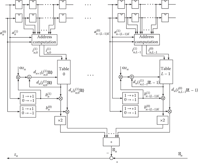
FIGURE 10.6 Block diagram of an adaptive distributed-arithmetic echo canceller.
The analyses of the mean square error convergence behavior and steady-state performance have been extended to adaptive distributed-arithmetic echo cancellers [1]. In this case, the dynamics of the mean square error are given by
The stability condition for the echo canceller is . For a given adaptation gain, the stability of the echo canceller depends on the number of tables and on the variance of the transmitted symbols. Therefore, the time span of the echo canceller can be increased without affecting system stability, provided that the number L of tables is kept constant. In that case, however, mean square error convergence will be slower. From Equation 10.17, we find that the optimum adaptation gain that permits the fastest mean square error convergence at the beginning of the adaptation process is αopt = 1/(Lσa2). The time constant of the convergence mode is τopt = L2K−1. The smallest achievable time constant is proportional to the total number of values. The realization of a distributed-arithmetic echo canceller can be further simplified by updating at each iteration only the values that are addressed by the most significant bits of the symbols stored in the delay line. The complexity required for adaptation can thus be reduced at the price of a slower rate of convergence.
10.3 Echo Cancellation for Quadrature Amplitude Modulation Systems
Although most of the concepts presented in the preceding sections can be readily extended to echo cancellation for communications systems employing QAM, the case of full-duplex transmission over a voiceband data channel requires a specific discussion. We consider the system model shown in Figure 10.7. The transmitter generates a sequence {an} of i.i.d. complex-valued symbols from a two-dimensional constellation , which are modulated by the carrier , where T and fc denote the modulation interval and the carrier frequency, respectively. The discrete-time signal at the output of the transmit Hilbert filter may be regarded as an analytic signal, which is generated at the rate of m/T samples/s, m > 1. The real part of the analytic signal is converted into an analog signal by a D/A converter and input to the channel. We note that by transmitting the real part of a complex-valued signal positive- and negative-frequency components become folded. The image band attenuation of the transmit Hilbert filter thus determines the achievable echo suppression. In fact, the receiver cannot extract aliasing image-band components from desired passband frequency components, and the echo canceller is able to suppress only echo arising from transmitted passband components.
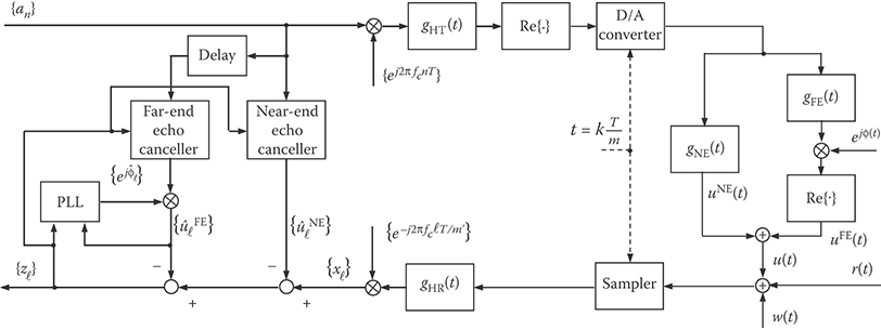
FIGURE 10.7 Configuration of an echo canceller for a QAM transmission system.
The output of the echo channel is represented as the sum of two contributions. The near-end echo uNE(t) arises from the impedance mismatch between the hybrid and the transmission line, as in the case of baseband transmission. The far-end echo uFE(t) represents the contribution due to echos that are generated at intermediate points in the telephone network. These echos are characterized by additional impairments, such as jitter and frequency shift, which are accounted for by introducing a carrier-phase rotation of an angle φ(t) in the model of the far-end echo.
At the receiver, samples of the signal at the channel output are obtained synchronously with the transmitter timing, at the sampling rate of m/T samples/s. The discrete-time received signal is converted to a complex-valued baseband signal {xnm′+i, i = 0, …, m′ – 1}, at the rate of m′/T samples/s, 1 < m′ < m, through filtering by the receive Hilbert filter, decimation, and demodulation. From delayed transmit symbols, estimates of the near- and far-end echo signals after demodulation, and , respectively, are generated using m′ interleaved near- and far-end echo cancellers. The cancellation error is given by
A different model is obtained if echo cancellation is accomplished before demodulation. In this case, two equivalent configurations for the echo canceller may be considered. In one configuration, the modulated symbols are input to the transversal filter, which approximates the passband echo response. Alternatively, the modulator can be placed after the transversal filter, which is then called a baseband transversal filter [15].
In the realization considered, the estimates of the echo signals after demodulation are given by
and
where and are the coefficients of the m′ interleaved near- and far-end echo cancellers, respectively, is the sequence of far-end echo phase estimates, and DFE denotes the bulk delay accounting for the round-trip delay from the transmitter to the point of echo generation. To prevent overlap of the time span of the near-end echo canceller with the time span of the far-end echo canceller, the condition DFE > NNE must be satisfied. We also note that, because of the different nature of near- and far-end echo generation, the time span of the far-end echo canceller needs to be larger than the time span of the near-end echo canceller, that is, NFE > NNE.
Adaptation of the filter coefficients in the near- and far-end echo cancellers by the LMS algorithm leads to
and
respectively, where the asterisk denotes complex conjugation.
The far-end echo phase estimate is computed by a second-order phase-lock loop algorithm, where the following stochastic gradient approach is adopted:
where ℓ = nm′ + i, i = 0, …, m′ – 1, γFE and ζFE are step-size parameters, and
We note that algorithm (10.23) requires m′ iterations per modulation interval, that is, we cannot resort to interleaving to reduce the complexity of the computation of the far-end echo phase estimate.
10.4 Echo Cancellation for Orthogonal Frequency Division Multiplexing Systems
Orthogonal frequency division multiplexing (OFDM) is a modulation technique whereby blocks of M symbols are transmitted in parallel over M subchannels by employing M orthogonal subcarriers. We consider a real-valued discrete-time channel impulse response {hi, i = 0, …, L} having length L + 1 << M. To illustrate the basic principles of OFDM systems, let us consider a noiseless ideal channel with impulse response given by {hi} = {δi}, where {δi} is defined as the discrete-time delta function. Modulation of the complex-valued input symbols at the n-th modulation interval, denoted by the vector An = {An(i), i = 0, …, M – 1}, is performed by an inverse discrete Fourier transform (IDFT), as shown in Figure 10.8. We assume that M is even, and that each block of symbols satisfies the Hermitian symmetry conditions, that is, An(0) and An(M/2) are real valued, and , i = 1, …, M/2 − 1. Then the signals an = {an(i), i = 0, …, M – 1} obtained at the output of the IDFT are real valued. After parallel-to-serial conversion, the M signals are sent over the channel at the given transmission rate M/T, where T denotes the modulation interval. At the output of the channel, the noiseless signals are received without distortion. Serial-to-parallel conversion yields blocks of M elements, with boundaries placed such that each block obtained at the modulator output is also presented at the demodulator input. Then demodulation performed by a discrete Fourier transform (DFT) will reproduce the blocks of M input symbols. The overall input–output relationship is therefore equivalent to that of a bank of M parallel, independent subchannels.
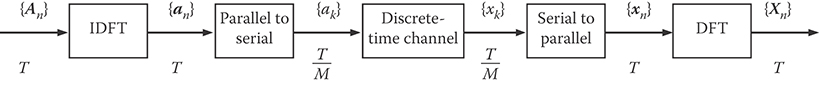
FIGURE 10.8 Block diagram of an OFDM system.
In the general case of a noisy channel with impulse response having length greater than one, M independent subchannels are obtained by a variant of OFDM that is also known as discrete multitone modulation (DMT) [12]. In a DMT system, modulation by the IDFT is performed at the rate 1/T′ = M/[(M + L)T] < 1/T. After modulation, each block of M signals is cyclically extended by copying the last L signals in front of the block, and converted from parallel to serial. The resulting L + M signals are sent over the channel. At the receiver, blocks of samples with length L + M are taken. Block boundaries are placed such that the last M samples depend only on the elements of one cyclically extended block of signals. The first L samples are discarded, and the vector xn of the last M samples of the block received at the n-th modulation interval can be expressed as
where h is the vector of the impulse response extended with M – L – 1 zeros, wn is a vector of additive white Gaussian noise samples, and Γn is an M × M circulant matrix given by
Recalling that , where is the M × M DFT matrix defined as , k, m = 0, …, M – 1, and diag(An) denotes the diagonal matrix with elements on the diagonal given by An, we find that the output of the demodulator is given by
where H denotes the DFT of the vector h, and Wn is a vector of independent Gaussian random variables. Equation 10.27 indicates that the sequence of transmitted symbol vectors can be detected by assuming a bank of M independent subchannels, at the price of a decrease in the data rate by a factor (M + L)/M. Note that in practice the computationally more efficient inverse fast Fourier transform and fast Fourier transform are used instead of IDFT and DFT.
We discuss echo cancellation for OFDM with reference to a DMT system [7,16], as shown in Figure 10.9. The real-valued discrete-time echo impulse response is {hE,i, i = 0, …, N – 1}, having length N < M. We initially assume N ≤ L + 1. Furthermore, we assume that the boundaries of the received blocks are placed such that the last M samples of the n-th received block are expressed by the vector
where is the circulant matrix with elements given by the signals from the remote transmitter, and hE is the vector of the echo impulse response extended with M – N zeros. In the frequency domain, the echo is expressed as Un = diag(An)HE, where HE denotes the DFT of the vector hE. In this case, the echo canceller provides an echo estimate that is given by , where Cn denotes the DFT of the vector cn of the N coefficients of the echo canceller filter extended with M – N zeros. In practice, however, we need to consider the case N > L + 1. The expression of the cancellation error is then given by

FIGURE 10.9 Configuration of an echo canceller for a DMT transmission system.
where the vector of the last M elements of the n-th received block is now , and is an M × M Toeplitz matrix given by
In the frequency domain, the cancellation error can be expressed as
where is an M × M upper triangular Toeplitz matrix. Equation 10.31 suggests a computationally efficient, two-part echo cancellation technique. First, in the time domain, a short convolution is performed and the result subtracted from the received signals to compensate for the insufficient length of the cyclic extension. Second, in the frequency domain, cancellation of the residual echo is performed over a set of M independent echo subchannels. Observing that Equation 10.31 is equivalent to , where , the echo canceller adaptation by the LMS algorithm in the frequency domain takes the form
where α is the adaptation gain, and denotes the transpose conjugate of We note that, alternatively, echo canceller adaptation may also be performed by the algorithm which entails a substantially lower computational complexity than the LMS algorithm, at the price of a slower rate of convergence.
In DMT systems, it is essential that the length of the channel impulse response be much less than the number of subchannels, so that the reduction in data rate due to the cyclic extension may be considered negligible. Therefore, equalization is adopted in practice to shorten the length of the channel impulse response. From Equation 10.31, however, we observe that transceiver complexity depends on the relative lengths of the echo and of the channel impulse responses. To reduce the length of the cyclic extension as well as the computational complexity of the echo canceller, various methods have been proposed to shorten both the channel and the echo impulse responses jointly [9].
Recently, multitone modulation techniques based on filter banks have been proposed in which the M-branch filters yield very high spectral containment of individual subchannel signals [3]. The filters are a frequency-shifted version of a prototype filter designed to reduce the interchannel interference to a level that is negligible compared with that of other noise signals. In this case, echo cancellation can be performed by taking into account, for each subchannel, only the echo generated by transmission in the opposite direction on the same subchannel. The implementation of per-subchannel echo cancellation then requires M adaptive echo cancellers.
10.5 Summary and Conclusions
Digital signal processing techniques for echo cancellation provide large echo attenuation, and eliminate the need for additional line interfaces and digital-to-analog and analog-to-digital converters that are required by echo cancellation in the analog signal domain. In voiceband modems for data transmission over the telephone network, digital techniques for echo cancellation allow a precise tracking of the carrier phase and frequency shift of far-end echos.
The realization of digital echo cancellers in transceivers for high-speed full-duplex data transmission today is possible at a low cost, thanks to the advances in VLSI technology. Digital techniques for echo cancellation are appropriate for NEXT cancellation in transceivers for transmission over cables at rates of several gigabits per second for local-area network applications.
References
1. Cherubini, G., Analysis of the convergence behavior of adaptive distributed-arithmetic echo cancellers. IEEE Trans. Commun., 41(11), 1703–1714, 1993.
2. Cherubini, G., Creigh, J., Ölçer, S., Rao, S.K., and Ungerboeck, G., 100BASE-T2: A new standard for 100 Mb/s Ethernet transmission over voice-grade cables. IEEE Commun. Mag., 35(11), 115–122, 1997.
3. Cherubini, G., Eleftheriou, E., and Ölçer, S., Filtered multitone modulation for very high-speed digital subscriber lines. IEEE J. Sel. Areas Commun., 20(5), 1016–1028, 2002.
4. Cherubini, G., Ölçer, S., and Ungerboeck, G., A quaternary partial-response class-IV transceiver for 125 Mbit/s data transmission over unshielded twisted-pair cables: Principles of operation and VLSI realization. IEEE J. Sel. Areas Commun., 13(9), 1656–1669, 1995.
5. Duttweiler, D.L., Adaptive filter performance with nonlinearities in the correlation multiplier. IEEE Trans. Acoust., Speech, Signal Processing, 30(8), 578–586, 1982.
6. Falconer, D.D., Adaptive reference echo-cancellation. IEEE Trans. Commun., 30(9), 2083–2094, 1982.
7. Ho, M., Cioffi, J.M., and Bingham, J.A.C., Discrete multitone echo cancellation. IEEE Trans. Commun., 44(7), 817–825, 1996.
8. Lee, E.A. and Messerschmitt, D.G., Digital Communication, 2nd ed., Kluwer Academic Publishers, Boston, MA, 1994.
9. Melsa, P.J.W., Younce, R.C., and Rohrs, C.E., Impulse response shortening for discrete multitone transceivers. IEEE Trans. Commun., 44(12), 1662–1672, 1996.
10. Messerschmitt, D.G., Echo cancellation in speech and data transmission. IEEE J. Sel. Areas Commun., 2(2), 283–297, 1984.
11. Messerschmitt, D.G., Design issues for the ISDN U-Interface transceiver. IEEE J. Sel. Areas Commun., 4(8), 1281–1293, 1986.
12. Ruiz, A., Cioffi, J.M., and Kasturia, S., Discrete multiple tone modulation with coset coding for the spectrally shaped channel. IEEE Trans. Commun., 40(6), 1012–1029, 1992.
13. Smith, M.J., Cowan, C.F.N., and Adams, P.F., Nonlinear echo cancellers based on transpose distributed arithmetic. IEEE Trans. Circuits Systems, 35(1), 6–18, 1988.
14. Ungerboeck, G., Theory on the speed of convergence in adaptive equalizers for digital communication. IBM J. Res. Develop., 16(6), 546–555, 1972.
15. Weinstein, S.B., A passband data-driven echo-canceller for full-duplex transmission on two-wire circuits. IEEE Trans. Commun., 25(7), 654–666, 1977.
16. Ysebaert, G., Pisoni, F., Bonaventura, M., Hug, R., and Moonen, M., Echo cancellation in DMT-receivers: Circulant decomposition canceler. IEEE Trans. Signal Processing, 52(9), 2612–2624, 2004.
Further Reading
For further information on adaptive transversal filters with application to echo cancellation, see Adaptive Filters: Structures, Algorithms, and Applications, M.L. Honig and D.G. Messerschmitt, Kluwer, 1984.