7. Programming Motors and Servos
Robot Sensitivity Training Lesson #7 A robot’s sensors can cause its grasp to exceed its reach.
In Chapter 5, “A Close Look at Sensors,” and Chapter 6, “Programming the Robot’s Sensors,” we discussed sensors: what they sense, how they sense, and of course how to program them. We saw that without sensors, a robot does not know the state of the environment, what is going on, or the current conditions. With that information, decisions are made and tasks can be performed for the situation. That activity is implemented by the actuators of the robot(s). Actuators are the mechanisms that allow robots to act upon the environment.
Actuators Are Output Transducers
In Chapter 5, we discuss how sensors, input transducers, can convert physical quantities into electrical energy. Figure 5.1 showed how a sound sensor transforms sound waves into an electrical signal measured in decibels. Figure 7.1 shows the conversion of an electromagnetic sound wave back to an acoustic wave performed by the output transducer, a loud speaker.

A special type of output transducer is an actuator. Actuators are devices that convert energy into physical motion such as:
![]() Potentiometer
Potentiometer
![]() Accelerometer
Accelerometer
![]() Linear and rotary motors
Linear and rotary motors
All these devices convert electrical signals to electromechanical energy. In this chapter we focus on rotary motors used as joints for robotic arms and end-effectors and to make robots mobile with wheels, tracks, and legs.
Different types of motors have different purposes. Some are more powerful than others and are good for moving large robots; others are better at more intricate motor skills, such as robot arms and end-effectors. When designing, building, and ultimately programming a robot, you should understand the different types of motors, their characteristics, and how they are used.
Motor Characteristics
Here are a few characteristics common to all motors. This is what should be considered when trying to determine what motors should be used for the robot components. Watch for these characteristics in the datasheets about a motor.
Voltage
The rated voltage of a motor is how much voltage is needed for the motor to operate at its peak efficiency. Most DC motors can operate a little above or below their rated voltage, but it’s best not to plan on having it operate at those levels. The motor operating below the rated voltage reduces the motor’s power; maybe other choices should be made. Operating above the rated voltage can burn out the motor. Motors should operate at their top speed/rated voltage at some point. Its slowest speed should be no more than 50% less than the rated voltage.
Current
Motors draw current depending on the load they’re pulling. More load means more current usually. Every motor has a stall current, the current it draws when it’s stopped by an opposing force. This current is much higher than the running current, or current that it draws under no load. The power supply for a motor should be capable of handling the stall current. When starting up, motors may draw near the stall current for a little while to overcome their inertia.
Speed
Motor speed is given in rotations per minute (RPMs).
Torque
Torque is the measure of a motor’s capability to pull measured by the force a motor can pull when the opposing force (load) is attached to the motor’s shaft. This measurement can be ft.-lb., lb-ft., oz.-in, in.-oz., g-cm (gram-centimeter), and any other weight to length variation.
Resistance
A motor can be rated in ohms. This is the resistance of the motor. Using Ohm’s Law (voltage = current × resistance), you can calculate the motor’s current draw.
Different Types of DC Motors
There are two types of actuators that motors can fall into:
![]() Linear
Linear
![]() Rotational
Rotational
A linear actuator creates linear motion—that is, motion along one straight line. This type of actuator is important and useful for certain robot situations, but we do not discuss them in this book. Rotational actuators transform electrical energy into a rotating motion. Many types of motors are rotational actuators, and what distinguishes one type of motor from another are two main mechanical characteristics: torque and rotational speed. Torque is the force the motor can produce at a given distance and rotational speed has to do with how fast an object can rotate around an axis, the number of turns of the object divided by time. So this means a motor is defined by how much power it can exert and how fast it can go. The following three kinds of motor are discussed in this chapter:
![]() Direct current
Direct current
![]() Servo
Servo
![]() Geared direct current
Geared direct current
Although three motors are listed, all are different types of direct current (DC) motors. A servo motor is really a DC motor with a gear train.
Direct Current (DC) Motors
DC (direct current) motors and servos give robots physical action, such as walking if bipedal, rolling with tractor wheels, picking up and manipulating objects if the robots have arms. Considering those physical actions, when should a DC motor be used and when should a servo be used? What is the difference between a DC motor and a servo motor?
A DC motor comes in a variety of shapes and sizes, although most are cylindrical. Figure 7.2 shows a DC motor.

DC stands for “direct current,” and that current causes the motor to rotate continuously at hundreds to tens of thousands RPM (rotations per minute). DC motors have two terminals (wires), and when direct current is applied to one terminal and grounding the other, the motor spins in one direction. When applying current to the other terminal and grounding the first terminal, the motor spins in the opposite direction. By switching the polarity of the terminals, the direction of the motor is reversed. Varying the current supplied to the motor varies the speed of the motor.
DC motors can be brushed and brushless. A brushed motor is made of an armature (a rotor), a commutator, brushes, an axle, and a field magnet. The armature or rotor is an electromagnet, and the field magnet is a permanent magnet. The commutator is a split-ring device wrapped around the axle that physically contacts the brushes, which are connected to opposite poles of the power source. Figure 7.3 shows the parts of the brushed DC motor and how it rotates.

The brushes charge the commutator inversely in polarity to the permanent magnet. This causes the armature to rotate. The rotation’s direction can be clockwise and/or counterclockwise; it can be reversed by reversing the polarity of the brushes like reversing the leads on the battery. This process continues as long as power is supplied.
A brushless DC motor has four or more permanent magnets around the perimeter of the rotor in a cross pattern. The rotor bears the magnets, so it does not require connections, commutator, or brushes. Instead of these parts, the motor has control circuitry, like an encoder, to detect where the rotor is at certain times. Figure 7.4 shows a brushless DC motor.

For many applications and uses, brush and brushless motors are comparable. But each has pros and cons. Brushed motors are generally inexpensive and reliable. Brushless motors are pretty accurate for uses that have to do with positioning. Table 7.1 lists some pros and cons.


Speed and Torque
Motors have to be controlled for them to be useful for a robot. They have to start, stop, and increase and decrease speed. The speed of the DC motor can be easily controlled by controlling the power level or the voltage supplied to the motor. The higher the voltage, the higher speed the motor tries to go. Pulse Width Modulation (PWM) is a way to control the voltage and therefore the speed of the motor. With the basic PWM, the operating power to the motors is turned on and off to modulate the current going to the motor. The ratio of the “on” time to the “off” time determines the speed of the motor. This is the duty cycle, the percentage the motor is on to the percentage the motor is off. Switching the power on and off fast enough makes it seem that the motor is slowing down without stuttering. When using this approach, not only is there a reduction of speed, there is also a proportional decrease in the torque output. There is an inverse relationship between torque and speed: As speed increases torque is reduced; as torque increases speed reduces. Figure 7.5 shows the relationship between torque, speed, and velocity.

Torque is the angular force that produces motor rotation measured in
![]() Pounds per feet (lb/in)
Pounds per feet (lb/in)
![]() Ounces per inch (oz/in)
Ounces per inch (oz/in)
![]() Newtons per meter (N/m)
Newtons per meter (N/m)
Torque is not a constant value; it can have different values depending on the given information or condition. For example, the stall torque is the measurement of torque when it is at its maximum. That means the greatest torque has been used to make the motor rotate from a standstill state. A full load is the amount of torque needed to produce the rated power (horsepower) at the full speed of the motor. The stall torque is often higher than the full load torque. Sometimes these values are supplied by the manufacturer on the motor’s data sheet. Sometimes other information is supplied and then stall and full load torque values can be calculated:
Full Load Torque = (Horse_Power * 5252) / RPM
Horsepower is measured in watts. To calculate stall torque:
Stall Torque = Powermax / RPM
No load speed is the measurement of the motor at its highest speed rotating freely with no torque. Between the stall and no load is the rated or nominal torque, which is the maximum torque that ensures continuous operation without problems. This is approximately about half of stall. The startup torque is the amount required by a robot to perform a task and should be around 20% to 30% of the maximum torque of the motor. Figure 7.6 shows the relationship of stall torque and no load falls on the graph.

Motors with Gears
Another way to reduce the speed of the motor without reducing the voltage and therefore the torque is by using gears. A motor rotates with high speed, but the torque generated by its rotation is not enough to move even a light load. The gearbox or gear mechanism takes high input speed of the motor and makes the output speed slower than the original input speed. This increases the torque. The rotation speed can be increased or decreased along with the corresponding increase or decrease in the torque. A number of things can be accomplished when transmitting power using gears:
![]() Change the rotational direction
Change the rotational direction
![]() Change the angle of rotation
Change the angle of rotation
![]() Convert rotational motion into linear motion
Convert rotational motion into linear motion
![]() Change the location of rotational motion
Change the location of rotational motion
Gear Fundamentals
Gearing down means using gears to slow down the output of the motor before it is applied to a shaft. Consider Figure 7.7 (a). The small gear (X) is called the pinion; it has 16 teeth. The large gear (Y), called the wheel, has 32 teeth. That’s double the teeth on the pinion. The ratio of the gears is the number of teeth on the wheel divided by the number of teeth on the pinion. So, there is a ratio of 2 to 1 between X and Y. This means that for each revolution of the pinion, the wheel makes a half turn. If a motor is connected to the pinion and the output shaft to the wheel, the motor speed is cut in half at the output shaft. Figure 7.7 (b) shows this configuration on the robot arm, which doubled the torque output.

Figure 7.7 Pinion and wheel gears: (a) pinion (X) has 16 teeth and wheel (Y) has 32 teeth; (b) photo of a robot arm using a pinion and wheel
The speed and torque of the wheel can be calculated given the speed or torque of the pinion:
TW = e(TPR)
SW = e(SP/R)
where TW and SW are the torque and speed of the wheel. TP and SP are the torque and speed of the pinion, R is the gear ratio, and e is the gearbox efficiency, which is a constant between 0 and 1.
R = 2
TP = 10 inch-pound
e = .8 (which is at 80% efficiency),
SP = 200 RMP
The output wheel torque will be:
16 pounds per inch = .8 (10 × 2)
The speed of the wheel will be:
80 RPM = .8 (200/2)
If a higher gear reduction is needed, adding more gears won’t do it and the efficiency will drop. The reduction of any gear is a function of the gear ratio, the number of teeth on the output gear connected to the shaft (follower gear Y) divided by the number of teeth on the input gear connected to the motor (driver gear X). Adding gears between the driver and the follower, called idlers, does not cause an increase in the gear ratio between the same two gears. To have a larger gear ratio, gears can be layered. Attach a pinion (smaller gear X2) to the wheel shaft Y and use that second pinion to drive the larger wheel (Y2) as shown in Figure 7.8.

As far as size, say:
X = X2
Y = Y2
The gear ratio is shown. X2 attached to Y rotates at the same speed. Therefore, X revolves 4 times (input rotations) to every 1 revolution of Y (output rotation), 4:1 reduction. This is commonly done inside gearboxes. The gear efficiency should be supplied by the manufacturer of the gear on the data sheet based on the type of gear. Table 7.2 is a list of typical gears and their estimated efficiency constants. The gear ratio or reduction should also be supplied by the manufacturer.

Calculating the total gear reduction of a gearbox or drive train is simple. Multiply all the gear ratios of the gear sets. For example:
Gear set #1: 4:1
Gear set #2: 3:1
Gear set #3: 6:1
with a total gear reduction: 4 * 3 * 6 = 72:1
So if a motor has a speed of 3000 RPM with a gearbox of 72:1, then the RPM for the motor is 3000/72 = 42 RPM. Use the gear ratio to determine the effect on the torque of the motor.
Gears can also change the rotational direction. Two gears, like the wheel and pinion, can reverse the rotational output. So if the input wheel is turning counterclockwise, then output gear turns clockwise. But to have the output wheel to turn in the same direction, add an idler gear between them as in Figure 7.9.

Figure 7.9 Input (driver) wheel turning counterclockwise causes the output wheel to turn clockwise. Adding an idler wheel between them causes both wheels to turn in the same direction.
The output wheel now turns counterclockwise, the same as the input gear. But what if you have a chain of say four or five gears touching? The rule is this: With an odd number of gears, rotation (input and output gears) is in the same direction, and with an even number of gears, they are counterrotational and the gear ratio stays the same. The input and output gears are accessed; all idler gears are ignored. The gear efficiency is:
Total_gear_efficiency = gear_type_efficiency # of gears –1
DC Motor with Gearhead
Some DC motors have a gearbox and are called gearhead DC motors. Figure 7.10 shows the DC motor with a gearbox. The gearbox is on the shaft end on the motor. The gearbox makes the output of the motor or the turning of the shaft slower and more powerful without lowering the voltage.

Servos: DC Motors with Geartrain
Servo motors are a variation of the gearhead motor. They are coupled with a potentiometer (pot). A pot gives feedback on the motor’s position. Servo motors are used for precise positioning and speed control at high torques. They consist of a motor, position sensor, and controller. Servos have three wires. The first two are for power and ground, and the third is a digital control line. The digital control line is used to set the position of a servo. The small DC motor sensor, and controller are all inside a single plastic housing. Servo motors are available in power ratings from fractions of a watt up to a few 100 watts. A servo motor’s output shaft can be moved to a specific angular position or rotation speed by sending it a coded signal. The servo motor maintains the position of the shaft or speed as long as the same coded signal is applied. When the coded signal changes, the shaft changes too.
A servo motor turns 90° in either direction, with a maximum rotation of 180°. There are servos with a 360° rotation. A normal servo motor cannot rotate any more than that due to a built-in mechanical stop. Three wires are taken out of a servo: positive, ground, and control wire. A servo motor is controlled by sending a Pulse Width Modulated (PWM) signal through the control wire. A pulse is sent every 20 ms. The duration of the pulses determines the position of the shaft. For example, a pulse of 1 ms, minimum pulse, moves to 0°; a pulse of 2 ms, its maximum pulse, moves the shaft to 180°; and a pulse of 1.5 ms, neutral position, moves the shaft to 90°. This is shown in Figure 7.11.

If an external force is trying to change the position of the shaft, the motor resists the change. Pulses need to be repeated for the motor to hold the position. The potentiometer measures the position of the output shaft at all times so the controller can correctly place and maintain the servo shaft at the desired position.
The servo uses a closed-loop control, which gives feedback to the controller so adjustments can be made to maintain the desired position or speed of the motor’s output shaft. When the pulse changes, an error is calculated between the current position/speed and the new position/speed. The electrical pulse is first fed to a voltage converter. The current rotational position or speed of the output shaft is read by the tachometer/pot that produces a voltage. The tachometer/pot serves as an electromechanical device that converts mechanical rotation into an electrical pulse. The rotational position is related to the absolute angle of the output shaft. The signal representing the current position/speed and the signal representing the new or commanded position/speed are both fed to an Error Amplifier (EA). The output of the EA drives the motor. The EA determines the difference between the voltages: If the output is negative, the motor is moved in one direction, and if the output is positive, the motor is moved in the other direction. The greater the difference, the greater the voltage and the more the motor moves or turns, speeds up, or slows down. When the motor turns, this engages the gear system that turns the output shaft to the commanded position. The servo motor continuously makes adjustments, resisting any movements to maintain that feedback operation that occurs every so many milliseconds. This process is depicted in Figure 7.12.

The closed-loop system monitors the error difference between how fast/slow the robot’s motor is going, how fast/slow it should be going, and makes adjustments to the motor’s power level if necessary. Figure 7.13 shows an example of controlling the speed of the servo.

What Are Encoders For?
Encoders are used to track the turning of motor shafts to generate the digital position of the shaft and other motion information. They convert motion into a sequence of digital pulses. Encoders can be built in to the motors like servos or they can be external as in the case of the DC motor where they are mounted on the motor’s shaft. Figure 7.14 shows the location of the encoder for the DC motor and a LEGO servo.

Encoders can have a linear or rotary configuration, but the most common is the rotary type. There are two basic forms of rotary encoders: incremental and absolute. Incremental encoders produce a digital pulse as the shaft rotates, allowing the measurement of the relative position of the shaft. Absolute encoders have a unique digital word for each rotational position of the shaft. These are often paired with permanent-magnet brushless motors for servos.
Most of the rotary encoders are made of a glass or plastic code disk. Some have a photographically deposited radial pattern organized in tracks. The NXT LEGO servo has a black wheel with 12 openings or slits (refer to Figure 7.14 [b]). As the motor spins, the encoder wheel also spins interrupting a beam of light on one side of the wheel that is detected by sensors on the other side of the wheel. The rotation generates a series of on and off states. Bits can be combined to produce a single byte output of n bits as a parallel transmission.
The Tetrix encoders (manufactured by Pitsco) for DC motors are quadrature optical incremental encoders. This means the encoders output a relative position and the direction of the motor. For this type of encoder, the beam of light passes through an encoder that splits the light to produce a second beam of light 90° out of phase. Light passes from A and B channels through the wheel onto the photodiode array. The wheel rotation creates a light-dark pattern through the clear and opaque wheel segments. The pattern is read and processed by a photodiode array and decoding circuitry. Beams A and B are each received by a separate diode and converted into two signals 90° out of phase with respect to the other sensor. This output is called quadrature output. It’s then fed to a processor that can process the signal to determine the number of pulses, direction, speed, and other information. Figure 7.15 shows the incremental encoder disk, light, and sensors.

Figure 7.15 The encoder disk, light source, and sensors for a quadrature optical incremental encoder
The LEGO servo encoder wheel only has one level of slits where other servos have two levels, with a sensor for each level.
Motor Configurations: Direct and Indirect Drivetrains
There are different ways to connect the motors to the components that move or rotate. The way they are connected determines how well the motor mechanism performs in the situation. The drivetrain is a mechanical system that transfers rotational power from the motor to the drive wheels. There are two types of drivetrains:
![]() Direct transfer
Direct transfer
![]() Indirect transfer
Indirect transfer
For a direct drive transfer, the motor shaft is directly connected to the drive wheel. Direct drive transfer means there is no speed torque changes between the motor and the wheel and is mechanically efficient. But the parts in the direct drive system can wear down and break.
For an indirect drive transfer system, the motor shaft is connected to the drive wheel shaft through a gear train and maybe belts or chains. The gear train and belt reduce the speed of the motor while proportionately increasing motor torque. This also acts as a shock absorber when the drive wheels are stuck or under heavy load. Figure 7.16 shows the two types of drivetrains.

The drivetrains play an important role in the robot’s mobility and joints in the robot arm. Table 7.3 describes the drivetrains, their advantages, and disadvantages.

Terrain Challenge for Indoor and Outdoor Robots
Some of the robots discussed in this book are meant for indoor scenarios and situations. The birthday party scenario and Midamba’s predicament both take place indoors. Many robots are programmed to work indoors because indoor environments are safer and more predictable. The premise of programming autonomous robots for this book is to program them for scenarios totally under control and predictable environments. The challenges can be well thought out, and success is probable. But even indoor environments can introduce challenges for robots. Table 7.4 lists the different types of environments and some of the factors that should be considered for motors.

Dealing with Terrain Challenges
The challenges of terrain can be addressed by steering and driving systems, the type of mobility, as well as the torque and speed of the robot. Some terrains are better negotiated with legs, especially if climbing is needed (like stairs). Wheels and tracks are better with other types of terrain. If an object is to be transported, which type of mobility is better for the task? A robot with legs, wheels, or tractor wheels?
The size and weight of the robot becomes a factor in making these choices. Smaller robots may have fewer problems in controlled environments because they are faster and can easily get around known small obstacles. But on the other hand, if a robot has to travel from waypoint A from waypoint C in a certain time frame and over a thick carpeted area to reach waypoint C, would a larger robot be better? A smaller robot’s batteries may become depleted trying to supply its motors a high constant current to maintain a speed at the cost of torque. Those wheels are rotating, but the robot is not going very far. Maybe a larger robot with bigger wheels and more powerful motors is a better fit. It is less affected by the terrain, and the larger wheels cause the robot to travel farther but rotate slower. But bigger, heavier robots also have challenges. Larger robots draw more current. Farther distances mean drawing more current from the batteries, which are already being taxed. When the motor stalls, it draws a large amount of current. Does the larger robot have indirect drive that can help with lessening the load on the motors?
What type of mobility? If wheels, what size, what type? Are treads better across any type of terrain? They are the obvious choice for tough terrains, but they can complicate the mechanical design. Large wheels with four-wheel drive are also an obvious choice, but with larger wheels comes a decrease in the maximum available torque. Bipedal legs and legs that simulate other animals such as insects are much more complicated mechanical devices for mobile robots. They are good in narrow circumstances though. They are also good for tricky, inconsistent terrains, but they require a lot of servos and more importantly complex programming. The torque and speed capabilities depend on the motors they are using. Table 7.5 lists different types of robot mobility and the motor concerns for each.


Torque Challenge for Robot Arm and End-Effectors
What about the motors for the robot and end-effectors? What are the torque and maximum rotation requirements needed? The actuators needed for a robot arm depend on the type of robot arm and the DOF (Degrees of Freedom). DOFs are associated with the arm joints that have a motor at each joint. Each joint has a maximum rotation and a startup torque. Determining whether the arm is up to the task requires calculations and a clear picture of what the arm is expected to do. The end-effectors are the hands and tools of the robot. They also have to be evaluated. This is discussed in the section “Robotic Arms and End-Effectors” later in this chapter.
Calculating Torque and Speed Requirements
How are the calculation formulas for speed, torque, and whatever used to help pick motors so the robot can perform the task? Torque and speed calculations are used to determine whether the robot can safely perform the task based on the capabilities of its motors. The amount of torque required by a robot to perform a task is called the startup torque and should be around 20% to 30% of its maximum torque (refer to Figure 7.6). It should not exceed the rated torque for the motor. For example, say a robot must accelerate to a speed of 1 cm/s. The attributes for the potential robots to perform the task are listed in Table 7.6.

There are two robots to choose from to execute this task. There is a formula that relates the motor torque with the robot’s weight and acceleration desired. So this shows the torque needed for the task, the startup torque. This value should be no more than 20% to 30 % of the rated torque of the possible motors. A motion formula can be used that relates the weight of the robot, torque, and acceleration:
C/r = m * a + Fattr
where m = mass of the robot (weight in kg), r = radius of the wheel, a = the acceleration, and C is the torque. Fattr is the attrition force between the wheel and the floor. This has to do with the terrain challenges discussed earlier and can be difficult to determine. So for simplicity, we represent this value as m * a:
C/r = 2 (m * a)
Assuming the robot has two motors (left and right wheels), we calculate half this torque:
C = m * a * r
If C, the startup torque, is more than 20% to 30% of the rated torque of the motor, the robot will not be able to meet the desired acceleration. In this case, both the robot’s motors meet the torque requirement. The torque evaluation in Table 7.6 shows that the startup torque is only 5% of the small robot’s rated motor and 15% of the larger robot’s motor.
What about speed (RPM)? How fast can the robot to go? How can we calculate how many rotations per minute and how far per minute? To calculate the distance a wheel travels in one revolution, use this calculation:
distance = 2 * 3.141 * r
and the RPMs:
RPM = (ds / distance) * 60
In this case, the speed evaluation is a little different. The smaller robot’s motor cannot reach the desired speed and the larger robot’s motor can.
Motors and REQUIRE
All these characteristics and calculations should be used to help determine whether the robot is capable of executing a task. The REQUIRE (Robot Effectiveness Quotient Used in Real Environments) is a checklist that can be used to figure this out. Here, let’s make it clear that the actuator is one factor in making this determination. The goal for each factor (sensors, actuators, end-effectors, and microcontrollers) is to be as close to 100% as possible. For the tasks for the motors, use the calculations to make sure each of the tasks can be executed by the motors used. If so, 100% can be used for the actuators. Table 7.8 compares the DC and servo motors based on their advantages and disadvantages.

Programming the Robot to Move
Programming the motor is controlling the motor. We discussed earlier how motors are controlled by sending signals/commands for speed and positioning the shaft. Motor shafts coupled to wheels, legs, or tracks cause the robot to move. For wheeled and track wheeled robots, there are some basic movements:
![]() Forward in a straight line
Forward in a straight line
![]() Rotate
Rotate
![]() Arcs
Arcs
![]() Stop
Stop
These movements can be sequenced together so a mobile robot can perform some sophisticated maneuvering and traveling in an environment. Each type of movement requires some additional information for that movement to be executed. For example, to move a robot forward or backward in a straight line, the motor needs to know how far or for how long. A rotation requires angle and a direction, and so on. Here is a list:
![]() Forward: Time, heading, distance
Forward: Time, heading, distance
![]() Rotate: Angle in degrees, direction
Rotate: Angle in degrees, direction
![]() Arc: Radius, direction
Arc: Radius, direction
Some moves can also be coupled together, like arc-forward. These parameters can be positive or negative to cause clockwise or counterclockwise, left or right, forward or backward movements. And of course speed is a parameter for these moves. But how is a motor programmed to execute these moves? It depends on how many motors are involved and some other things.
One Motor, Two, Three, More?
The wheel drive of the robot is an important part of how the motors are programmed and affects the mobility performance. Just like a car, a wheeled robot can have two-wheel or four-wheel drive. With four-wheel drive, a motor drives each wheel. With two-wheel drive, the two motors are in the front or in the back. For a tracked wheeled robot, there may be just two gears with a motor on each and tracks wrapped around additional wheels. This is the wheel drive configuration for our robot depicted in Figure 7.19 along with some other wheel drive configurations.

Each type of wheel drive has advantages and disadvantages. More motors means more torque. We discussed earlier the various challenges for mobile robots, including the need for speed and torque to overcome weight, terrain, surface friction, and so on.
Making the Moves
There are different approaches to coordinate the motors to perform the forward, rotate, arc, and stop moves—for example, car-type steering called Ackerman steering, cab-drive steering, omni-directional wheels, and the differential steering method. The differential steering method is where the speed of the wheels is altered to change the direction the robot is moving or to turn the robot to some direction. Ackerman and the cab-drive steering has complex designs and servos and logic to control the robot. The simplest one for an introduction to programming autonomous robots is the basic differential steering method.
Differential steering creates different speeds and directions to perform the basic moves to make a robot mobile. With this method, there are typically two powered wheels, one on each side of the robot. Sometimes there are passive wheels that keep the robot from tipping over, like a castor wheel in the back. Here is a list of the basic operations for differential steering:
![]() When both wheels rotate at the same speed in the same direction, the robot moves straight in that direction (forward or backward).
When both wheels rotate at the same speed in the same direction, the robot moves straight in that direction (forward or backward).
![]() When one wheel rotates faster than the other, the robot turns in an arc toward the slower wheel.
When one wheel rotates faster than the other, the robot turns in an arc toward the slower wheel.
![]() When the wheels rotate in opposite directions, the robot turns in place.
When the wheels rotate in opposite directions, the robot turns in place.
![]() When the two wheels on each adjacent side (left and right) rotate on opposite spin at the same speed, the robot spins 360°.
When the two wheels on each adjacent side (left and right) rotate on opposite spin at the same speed, the robot spins 360°.
Programming the Moves
In this section, we will show BURT Translations for programming Tetrix DC motors using the EV3 microcontroller and the Tetrix Motor Controller. Listing 7.1 is the BURT Translation for programming the Tetrix DC motor using the leJOS API TetrixControllerFactory, TetrixMotorController, and TetrixRegulatedMotor classes. Listing 7.1 BURT Translation shows the pseudocode for testing motors and the Java code translation. This is the main line to test the motors by performing some basic operations.
BURT Translation Listing 7.1 Softbot Frame for Unit1’s Motor Test
BURT Translation INPUT ![]()
Softbot Frame
Name: Unit1
Parts:
Motor Section:
Two DC motors
Actions:
Step 1: Initialize motors
Step 2: Test the motors by performing some basic operators
Tasks:
Test the DC motors by performing some basic operations.
End Frame
BURT Translations Output: Java Implementations ![]()
73 public static void main(String [] args) throws Exception
74 {
75 basic_robot Unit1 = new basic_robot();
76 Unit1.testMotors();
77 Unit1.closeLog();
78 }
In line 75, the basic_robot is declared. Two functions/methods are then called. Listing 7.2 shows the code for the constructor.
Listing 7.2 Java Code for basic_robot Constructor
BURT Translations Output: Java Implementations ![]()
28 public basic_robot() throws InterruptedException,Exception
29 {
30 Log = new PrintWriter("basic_robot.log");
31 Port APort = LocalEV3.get().getPort("S1");
32 CF = new TetrixControllerFactory(APort);
33 Log.println("Tetrix Controller Factor Constructed");
34 MC = CF.newMotorController();
35 LeftMotor = MC.getRegulatedMotor(TetrixMotorController.MOTOR_1);
36 RightMotor = MC.getRegulatedMotor(TetrixMotorController.MOTOR_2);
37 LeftMotor.setReverse(true);
38 RightMotor.setReverse(false);
39 LeftMotor.resetTachoCount();
40 RightMotor.resetTachoCount();
41 Log.println("motors Constructed");
42 Thread.sleep(1000);
43 }
In line 31:
31 Port APort = LocalEV3.get().getPort("S1");
LocalEV3 is the instance of the EV3 microcontroller. This class is used to return various system resources connected to the microcontroller. This case, getPort(). returns the Port object for S1, the port where the DC motor controller is plugged in to. APort is passed to TetrixControllerFactory. In line 34:
34 MC = CF.newMotorController();
MC is a TetrixMotorController object, which is used to return instances of motor objects connected to it. In lines 35 and 36:
35 LeftMotor = MC.getRegulatedMotor(TetrixMotorController.MOTOR_1);
36 RightMotor = MC.getRegulatedMotor(TetrixMotorController.MOTOR_2);
LeftMotor and RightMotor are both TetrixRegulatedMotor objects. A regulated motor must have an encoder installed and connected to the controller for the methods to work properly. In lines 37 and 38:
37 LeftMotor.setReverse(true);
38 RightMotor.setReverse(false);
LeftMotor is set to go in reverse, and RightMotor is set to go forward. In lines 39 and 40:
39 LeftMotor.resetTachoCount();
40 RightMotor.resetTachoCount();
both motors’ tachometers are reset. A tachometer is a device that measures the rotation speed of the motor’s shaft measured in degrees. Resetting the tachometer causes the motor to stop rotating.
Listing 7.3 shows the BURT Translation for the testMotors() method and shows the pseudocode for testing motors and the Java code translation. This is the testMotors() method to test the motors by performing some basic operations.
BURT Translation Listing 7.3 Softbot Frame for Unit1’s testMotors() Method
BURT Translation INPUT ![]()
Softbot Frame
Name: Unit1
Parts:
Motor Section:
Two DC motors
Actions:
Step 1: Set speed of motors
Step 2: Rotate to the right
Step 3: Go forward
Step 4: Go backward
Step 5: Rotate to the left
Tasks:
Test the DC motors by performing some basic operations.
End Frame
BURT Translations Output: Java Implementations ![]()
48 public void testMotors() throws Exception
49 {
50 LeftMotor.setSpeed(300);
51 RightMotor.setSpeed(300);
52 LeftMotor.rotate(500,true);
53 RightMotor.rotate(-500);
54 Thread.sleep(2000);
55 LeftMotor.forward();
56 RightMotor.forward();
57 Thread.sleep(3000);
58 LeftMotor.backward();
59 RightMotor.backward();
60 Thread.sleep(2000);
61 RightMotor.rotate(500,true);
62 LeftMotor.rotate(-500);
63 Thread.sleep(2000);
64 LeftMotor.stop();
65 RightMotor.stop();
66 }
To program the motors to perform basic moves, each motor has to be controlled. To go forward based on the differential steering method, both wheels rotate at the same speed in the same direction; the robot moves straight in that direction (forward or backward).
In lines 50 and 51:
50 LeftMotor.setSpeed(300);
51 RightMotor.setSpeed(300);
both motors are set to the same speed. They are set to 300 deg/s2 (degrees per second squared). Setting or changing the speed on the motor requires an adjustment in the amount of power to the motor. The power value is derived from the passed value:
Power = Math.round((Value – 0.5553f) * 0.102247398f);
The actual speed value is not exact. The maximum reliably sustainable velocity for the Tetrix DC Gear motor is 154 RPM => 924 deg/s2.
To rotate the robot based on the differential steering method, wheels rotate in opposite directions; the robot turns in place.
In lines 52 and 53:
52 LeftMotor.rotate(500,true);
53 RightMotor.rotate(-500);
54 Thread.sleep(2000);
the motor rotates to the given Angle, measured in degrees to rotate the motor relative to the current position. LeftMotor is rotated to 500°, and RightMotor is rotated to –500°. This causes the robot to turn in place to the right. The true parameter is important. This means the method does not block but returns immediately so the next line of code can be executed. This is needed when coordinating the commands for both motors; they may have to execute their operations at the same time (close to it) to get the desired results. If true was not set, the LeftMotor would rotate before the RightMotor, causing a sloppy rotation; then the RightMotor would cause another sloppy rotation in the opposite direction. Thread.sleep() gives the robot time to perform the operation before executing the next commands.
Lines 55 and 56:
55 LeftMotor.forward();
56 RightMotor.forward();
cause both motors to go forward at the speed in the direction set in the constructor in lines 37 and 38:
37 LeftMotor.setReverse(true);
38 RightMotor.setReverse(false);
The motors can move forward, but they are set to move in opposite directions. How can they move forward? This is called inverting motors. How long will the robot move forward? Line 57:
57 Thread.sleep(3000);
is used for the time duration the robot is to move forward. In lines 58 and 59:
58 LeftMotor.backward();
59 RightMotor.backward();
the motors cause the robot to move backwards. Line 60:
60 Thread.sleep(2000);
is the time duration for this move.
In lines 61 and 62:
61 RightMotor.rotate(500,true);
62 LeftMotor.rotate(-500);
the motor rotates to the given Angle. LeftMotor is rotated to –500°, and the RightMotor is rotated to 500°. This causes the robot to turn in place to the left. In lines 64 and 65:
64 LeftMotor.stop();
65 RightMotor.stop();
both motors are stopped. Table 7.9 lists the classes used in Listings 7.1, 7.2, and 7.3.

Table 7.9 Classes Used in Listings 7.1, 7.2, and 7.3
Programming Motors to Travel to a Location
Mobile robots not only move around, forward, backward, and spin in place, they have things to do and places to be. They need to travel to a location to perform the task for a given situation. Now, this can be done by programming the motors as in Listing 7.3. It’s a lot of work to coordinate the motors to move; there will be more work to coordinate the motors to take the robot to a specific location:
1. A path to the location has to be figured out—a path where the robot can move around, avoid obstacles, and so on.
2. While the robot is traveling, it has to know where it is and where it is heading at any given point. It may be necessary to correct its heading and to make sure it has not missed the target.
3. The path has to be translated into instructions or moves. Starting from the current location, the moves have to be determined to get the robot to the target.
4. The moves are then executed and the target is reached.
Figure 7.20 shows a flow of how these steps can be used to get a robot to a target location.

Listing 7.4 is the constructor for testing the motors’ travel capabilities.
BURT Translation Listing 7.4 Unit1’s Travel Test Constructor
BURT Translations Output: Java Implementations ![]()
37 public basic_robot() throws InterruptedException,Exception
38 {
39 Log = new PrintWriter("basic_robot.log");
40 WheelDiameter = 7.0f;
41 TrackWidth = 32.0f;
42
43 Port APort = LocalEV3.get().getPort("S1");
44 CF = new TetrixControllerFactory(APort);
45 Log.println("Tetrix Controller Factor Constructed");
46
47 MC = CF.newMotorController();
48 SC = CF.newServoController();
49 LeftMotor = MC.getRegulatedMotor(TetrixMotorController.MOTOR_1);
50 RightMotor = MC.getRegulatedMotor(TetrixMotorController.MOTOR_2);
51 LeftMotor.setReverse(true);
52 RightMotor.setReverse(false);
53 LeftMotor.resetTachoCount();
54 RightMotor.resetTachoCount();
55 Log.println("motors Constructed");
56 Thread.sleep(1000);
58 D1R1Pilot = new DifferentialPilot(WheelDiameter,
TrackWidth,LeftMotor,RightMotor);
59 D1R1Pilot.reset();
60 D1R1Pilot.setTravelSpeed(10);
61 D1R1Pilot.setRotateSpeed(30);
62 D1R1Pilot.setMinRadius(30);
63 Log.println("Pilot Constructed");
64 Thread.sleep(1000);
65
66 CurrPos = new Pose();
67 CurrPos.setLocation(0,0);
68 Odometer = new OdometryPoseProvider(D1R1Pilot);
69 Odometer.setPose(CurrPos);
70 Log.println("Odometer Constructed");
71 Thread.sleep(1000);
72
73 D1R1Navigator = new Navigator(D1R1Pilot);
74 D1R1Navigator.singleStep(true);
75 Log.println("Navigator Constructed");
76 Thread.sleep(1000);
77 }
In the constructor, several new objects are declared. In lines 40 and 41:
40 WheelDiameter = 7.0f;
41 TrackWidth = 32.0f;
WheelDiameter, TrackWidth, LeftMotor, and RightMotor are parameters used to declare a DifferentialPilot object in line 58. DifferentialPilot defines methods that control robot movements such as travel forward or backward in a straight line or in a circular path, or rotate to a new direction.
The DifferentialPilot class only works with a wheel drive with two independently controlled motors, so a rotation turns the robot in place. WheelDiameter is the diameter of the wheel, and TrackWidth is the distance between the center of the right tire and the center of the left tire.
The following methods:
50 D1R1Pilot.reset();
60 D1R1Pilot.setTravelSpeed(10);
61 D1R1Pilot.setRotateSpeed(30);
62 D1R1Pilot.setMinRadius(30);
are all self-explanatory. All these methods sets the tachometer, travel speed, rotation speed, and minimum radius for both motors.
Line 68:
68 Odometer = new OdometryPoseProvider(D1R1Pilot);
declares an OdometryPoseProvider object. OdometryPoseProvider keeps track of the location and heading of the robot. A Pose object represents the location and heading (direction angle) of a robot. This class includes methods that update the Pose as the robot moves. All directions and angles are in degrees. The direction 0 is parallel to the X axis, and direction +90 is parallel to the Y axis. The Pose is passed to the OdometryPoseProvider in line 69:
69 Odometer.setPose(CurrPos);
In lines 73 and 74:
73 D1R1Navigator = new Navigator(D1R1Pilot);
74 D1R1Navigator.singleStep(true);
the Navigator object is declared. Navigator controls a robot’s path traversal. If given multiple x,y locations (waypoints), the robot traverses the path by traveling to each waypoint in the order assigned. The singleStep() method controls whether the robot stops at each waypoint.
Listing 7.5 is the BURT Translation for the testMoveTo() method and shows the pseudocode for testing travel capabilities and the Java code translation. This is the testMoveTo() method to test the motors by performing some basic operations.
BURT Translation Listing 7.5 Softbot Frame for Unit1’s testMoveTo() Method
BURT Translation INPUT ![]()
Softbot Frame
Name: Unit1
Parts:
Motor Section:
Two DC motors
Actions:
Step 1: Report the current location of the robot
Step 2: Navigate to a location
Step 3: Travel a distance
Step 4: Rotate
Step 5: Report the current location of the robot
Tasks:
Test the traveling capabilities by performing some basic operations.
End Frame
BURT Translations Output: Java Implementations ![]()
80 public void rotate(int Degrees)
81 {
82 D1R1Pilot.rotate(Degrees);
83 }
84
85 public void forward()
86 {
87 D1R1Pilot.forward();
88 }
89
90 public void backward()
91 {
92 D1R1Pilot.backward();
93 }
94
95 public void travel(int Centimeters)
96 {
97 D1R1Pilot.travel(Centimeters);
98 }
99
100 public Pose odometer()
101 {
102 return(Odometer.getPose());
103 }
104
105 public void navigateTo(int X,int Y)
106 {
107 D1R1Navigator.clearPath();
108 D1R1Navigator.goTo(X,Y);
109 }
110
111 public void testMoveTo() throws Exception
112 {
113 Log.println("Position: " + odometer());
114 navigateTo(100,200);
115 Thread.sleep(6000);
116 travel(30);
117 Thread.sleep(1000);
118 rotate(90);
119 Thread.sleep(1000);
120 Log.println("Position: " + odometer());
121 }
Line 113:
113 Log.println("Position: " + odometer());
reports the current location of the robot. The odometer() method:
100 public Pose odometer()
101 {
102 return(Odometer.getPose());
103 }
calls the OdometerPoseProvider getPose() method, which returns a Pose object, which is reported to the log, for example:
Position: X:30.812708 Y:24.117397 H:62.781242
x, y, and heading are represented as floats.
In lines 114 and 116:
114 navigateTo(100,200);
116 travel(30);
are two methods to move a robot to a target location. The navigateTo(100,200) method:
105 public void navigateTo(int X,int Y)
106 {
107 D1R1Navigator.clearPath();
108 D1R1Navigator.goTo(X,Y);
109 }
is a wrapper for two Navigator methods. The clearPath() method clears any current paths. The goTo() method moves the robot toward the x, y location. If no path exists, a new one is created. The travel() method:
95 public void travel(int Centimeters)
96 {
97 D1R1Pilot.travel(Centimeters);
98 }
is a wrapper for the DifferentialPilot travel() method and moves the robot in a straight line the given centimeters. The robot travels forward if the value is positive and backward if the value is negative. When programming the motors to travel forward, each motor has to be given a forward command but no way to specify the distance.
Other methods are wrappers for the DifferentialPilot methods:
backward()
forward()
These methods move the robot forward or backward in a straight line. These methods perform similarly to the forward and backward methods for TetrixRegulatedMotor, but they move both motors. Table 7.10 lists the classes used in Listings 7.4 and 7.5.

Table 7.10 Classes Used in Listings 7.4 and 7.5
Programming Motors Using Arduino
In this section, we show BURT Translations for programming brushless motors using the Arduino Uno microcontroller and Servo.h library. Listing 7.6 is the BURT Translation for programming the brushless (hobby servo) motor using 5V line. Listing 7.6 also shows the pseudocode for testing the motor and the C++ code translation.
BURT Translation Listing 7.6 Softbot Frame for Servo Motor Positioning Test
BURT Translation INPUT ![]()
Softbot Frame
Name: ServoMotor
Parts:
Motor Section:
1 standard brushless servo motor
Actions:
Step 1: Initialize motor
Step 2: Position the servo from 0 to 180º in 5º increments
Step 3: Position the servo from 180 to 0º in 5º increments
Tasks:
Test the servo motor by controlling its position.
End Frame
BURT Translations Output: Java Implementations ![]()
1 #include <Servo.h>
2
3 Servo ServoMotor;
4
5 int Angle = 0;
6
7
8 void setup()
9 {
10 ServoMotor.attach(9);
11 }
12
13 void loop()
14 {
15 for(Angle = 0; Angle < 180; Angle += 5)
16 {
17 ServoMotor.write(Angle);
18 delay(25);
19 }
20
21 for(Angle = 180; Angle >= 5; Angle -= 5)
22 {
23 ServoMotor.write(Angle);
24 delay(25);
25 }
26 }
In line 10 in the setup() function, the attach() function connects the servo on pin 9 to the ServoMotor object. Certain versions of the Servo library support servos only on two pins: 9 and 10. In the loop() function, there are two for loops. The first for loop positions the angle of the servo from 0° to 180° in 5° increments. The second for loop positions the angle of the servo from 180° to 0° in 5° increments. The write() function sends a value to the servo that controls the shaft. If a standard servo is being used, this sets the angle of the shaft in degrees. If a continuous rotation servo is being used, this sets the speed of the servo with 0 being the full-speed of the servo in one direction, 180 being the full speed of the motor in the other direction, and 90 being no movement. The delays are used to allow time for the motor to position. Testing the speed of a continuous motor is done in Listing 7.7.
Listing 7.7 BURT Translation shows the pseudocode for testing two continuous servo motors’ speed.
BURT Translation Listing 7.7 Softbot Frame for Two Servo Motors’ Speed Test
BURT Translation INPUT ![]()
Softbot Frame
Name: ServoMotor
Parts:
Motor Section:
2 continuous brushless servo motor
Actions:
Step 1: Initialize motors
Step 2: Rotate servos in the same direction from 90 to
180º in 5º increments to increase speed
Step 3: Rotate servos in the same direction from 180 to
90º in 5º increments to decrease
Tasks:
Test the servo motors by controlling their speed.
End Frame
BURT Translations Output: Java Implementations ![]()
1 #include <Servo.h>
2
3 Servo LeftServo;
4 Servo RightServo;
5
6 int Angle = 0;
7
8 void setup()
9 {
10 LeftServo.attach(9);
11 RightServo.attach(10);
12 }
13
14 void loop()
15 {
16 for(Angle = 90; Angle < 180; Angle += 5)
17 {
18 LeftServo.write(Angle);
19 RightServo.write(Angle);
20 delay(25);
21 }
22
23 for(Angle = 180; Angle >= 90; Angle += 5)
24 {
25 LeftServo.write(Angle);
26 RightServo.write(Angle);
27 delay(25);
28 }
29 }
In Listing 7.7, there are two continuous rotating servos: LeftServo and RightServo. The write() function in this case causes the motors to increase or decrease their speed or stop rotating. In the first for loop, the control variant starts at 90°; the motors are not moving. Angle increases in 5° increments until it reaches 180°, the motors at full throttle. In the second for loop, the control variant starts at 180°; the motors are at full throttle. Angle decreases in 5° increments until it reaches 90°; the motors have stopped.
Robotic Arms and End-Effectors
Motors are also used to control a robotic arm and its end-effectors. Controlling a robotic arm means controlling each motor in the arm. Since the goal is to have intricate control for positioning, servo motors are used. Wherever there is a servo on the arm, this is considered a joint and a DOF. What defines a robot’s motion capabilities is its degree of freedom, rotational range at each joint, and the dimension of space the arm works in, 2D or 3D. Movement can be determined by the rotation or a translation motion working in 2D or 3D space. The translational motion is how the joint can move forward and backward. This is defined by the type of robot arm being used. The end-effector of a robot arm is the device at the end of the robot. The end-effector is designed to interact with the environment and is some type of a gripper or a tool. That end-effector also is controlled by servos.
Robot Arms of Different Types
A robot arm has a length, joints, gripper, and maybe some type of tool. Figure 7.21 shows the basic components of a robot arm.

A robot arm can be a standalone device with or without mobility, or it can be attached to a fully functioning robot. There are different types of robot arms, and each is characterized by
![]() Configuration space
Configuration space
![]() Workspace
Workspace
The configuration space is the limitations of the robot arm’s DOF. The workspace is the reachable space of the end-effector in 2D or 3D space. Figure 7.22 shows a few different types of robot arms and their configuration space and workspace.

Each rotary joint has restrictions or limitations to its movements based on the rotational range of the servo at that joint. But how much rotation is needed depends on the design or the location of the arm and the application. The translational motions are forward, backward, vertical, or horizontal. The sum of all the configuration spaces for all the joints of the arm, lengths of links (one joint to the next), the angle objects can be lifted, and so on define the workspace. It determines the fixed boundaries of the possible locations of the end-effector. Outside the workspace is where the end-effector cannot reach. A mobile robot can include the area the robot could physically relocate to. Inverse and forward kinematics is the method of figuring out the orientation and position of joints and end-effectors given the link lengths and joint angles. A discussion on kinematics is presented briefly at the end of this chapter.
Torque of the Robot Arm
Calculating the torque of the robot arm boils down to the combined torque of each servo in the arm. Just like calculating the torque of the DC motors to determine whether it was capable of moving the robot, the torque of the arm must be enough to lift a desired object, maybe carry or manipulate it. But now multiple servos, lengths of links, pivot points, and so on have to be considered. Figure 7.23 labels weights, joints, and lengths of links for a robot arm with 2 DOF used to lift an object.

The torque of each servo is calculated. To do this the robot arm has to be stretched to its maximum length; this is the maximum torque required. Also, the weight and length of each link, weight of each joint, and weight of the object to be lifted have to be figured out. The center of mass of each link is Length/2. Here are the calculations:
Torque About Joint A:
T1 = L1 / 2 * W1 + L1 * W4 + (L1 + L2 / 2 ) * W2 + (L1 + L3 ) * W3
Torque About Joint B:
T2 = L2 / 2 * W1 + L3 * W3
Each DOF added makes these calculation more complicated. The more DOF, the higher the torque requirements. Again, this torque calculation is the amount of torque needed for each joint. It should be well below its maximum torque. Table 7.11 shows the calculation performed on a 2 DOF robot arm. Based on this calculation, T2 has enough torque, but T1 does not.

For a robot arm that is purchased, this information should be supplied. If the torque required is determined, it can be compared to the stats of the arm. Table 7.12 contains the specification for the PhantomX Pincher robot arm used for Unit1.

Different Types of End-Effectors
End-effectors are designed to interact with the environment. They are what deliver the goods and do whatever task is to be performed. The arm delivers the end-effector to the point in space where it needs to be at the right time. There are many types of end-effectors:
![]() Mechanical grippers
Mechanical grippers
![]() Negative pressure (vacuum)
Negative pressure (vacuum)
![]() Magnetic
Magnetic
![]() Hooks
Hooks
![]() Ladles (scoops liquid or powder)
Ladles (scoops liquid or powder)
![]() Others (electrostatic)
Others (electrostatic)
We used mechanical type end-effectors for the two robot arms. RS Media also has robot arms and end-effectors of a mechanical type. These are the most common. Mechanical grippers can be classified as:
![]() Parallel grippers
Parallel grippers
![]() Angular gripper
Angular gripper
![]() Toggle gripper
Toggle gripper
Figure 7.24 shows mechanical type end-effectors used for our two robots.

Table 7.13 shows the robot arm and end-effector types for the Unit1 and Unit2 robots.

Once it has been determined that the torque of the arm can lift the object, the end-effector should be evaluated. Just because the arm’s servos can lift the object does not mean that the end-effector can grip and hold the object. To determine whether the end-effectors of a robot can be used to transport an object, a calculation can be performed to determine whether it has the force to hold the object:
F = μ * Wobj * n
where F is the force required to hold the object, μ is the coefficient of the friction, Wobj is the weight of the object, and n is the number of fingers on the gripper.
But the torque of the gripper is not the sole factor. Other aspects of the gripper have to be considered. Look at the end-effectors of the three robot arms we used. Gripping implies there are mechanical fingers of some type. RS Media has hands, but they were not constructed to hold anything the size of the beaker. Robot arm 1 is the PhantomX Pincher Arm with 5 DOF including the end-effector. Based on its stats in Table 7.12, the gripper could hold the beaker:
.297 kg < .5 kg
but not at the wrist:
.297 kg > .25 kg
The other issue is the diameter of the beaker. The grip of the end-effector does not open wide enough. Unit1’s robot arm 2 end-effector can hold the beaker as depicted in Figure 7.25.

Programming the Robot Arm
In this section, we show the constructor for robot arm 2 (see Figure 7.26) using the EV3 microcontroller and Tetrix servo motors using the leJOS API TetrixServoController and TetrixServo classes (see Listing 7.8). Robot arm 2 has one DOF and a single servo to open and close the gripper.

BURT Translation Listing 7.8 Unit1’s Constructor for Servos for the Robot Arm and Gripper
BURT Translations Output: Java Implementations ![]()
9 TetrixServoController SC;
...
12 TetrixServo Arm;
13 TetrixServo Gripper;
31 public basic_robot() throws InterruptedException,Exception
32 {
33
...
49 Gripper = SC.getServo(TetrixServoController.SERVO_2);
50 Arm = SC.getServo(TetrixServoController.SERVO_1);
51 Log.println("Servos Constructed");
52 Thread.sleep(3000);
53 SC.setStepTime(7);
54 Arm.setRange(750,2250,180);
55 Arm.setAngle(100);
56 Thread.sleep(3000);
57 Gripper.setRange(750,2250,180);
58 Gripper.setAngle(50);
59 Thread.sleep(1000);
...
84 }
Lines 9, 12, and 13, and lines 49 through 59 have been added to the constructor. In lines 49 and 50:
49 Gripper = SC.getServo(TetrixServoController.SERVO_2);
50 Arm = SC.getServo(TetrixServoController.SERVO_1);
Gripper and Arm are assigned the TetrixServo objects for the servos for the arm and gripper. Line 53:
53 SC.setStepTime(7);
sets the “step time” for all servos plugged in to this controller. The step time is a delay before going on to the next command to be executed. This is similar to the sleep() methods, but where sleep() just waits until a command finishes executing, a step actually slows down the execution of a command or function. The value of steps is between 0 to 15. The isMoving() method always returns false if the step time is set to zero.
These methods:
54 Arm.setRange(750,2250,180);
55 Arm.setAngle(100);
...
57 Gripper.setRange(750,2250,180);
58 Gripper.setAngle(50);
are the workhorse methods for the arm and gripper. As discussed earlier in this chapter, the duration of the pulse determines the rotation of the servo motor. The setPulseWidth() method can be used to set the position of the robot arm. The width of the pulse must be within the maximum angle range of the servo. This method uses an absolute pulse and not a “relative” pulse width measured in microseconds. The parameter is between 750 to 2250 microseconds with a step resolution of 5.88 microseconds. A neutral position is 1500 microseconds width, the midpoint range of the servo.
The setRange() method sets the pulse width within the range of the servo in microseconds and the total travel range. For example, a 180° or 90° servo is the total travel range for the Hitec servos. The default total range is 200° with the low at 750 and high at 2250. This information must reflect the actual empirical specifications of a servo to be able to position the servo accurately. It accepts three parameters:
![]()
microsecLOW: The low end of the servo response/operating range in microseconds
![]()
microsecHIGH: The high end of the servo response/operating range in microseconds
![]()
travelRange: The total mechanical travel range of the servo in degrees
In these cases, the arm and gripper servos have a range of 180°, taking advantage of the low and high microseconds for intricate positioning of the servos. The setAngle() method sets the angle target of the servo. Its accuracy depends on the parameters set in setRange().
These methods are used to set the position of the robot arm and the gripper. Listing 7.9 contains the methods to position both Gripper and Arm servo objects.
BURT Translation Listing 7.9 Methods to Move the Gripper and Arm Servo Objects
BURT Translations Output: Java Implementations ![]()
87 public void moveGripper(float X) throws Exception
88 {
89
90 Gripper.setAngle(X);
91 while(SC.isMoving())
92 {
93 Thread.sleep(1000);
94 }
95 }
96
97 public void moveArm(float X) throws Exception
98 {
99
100 Arm.setAngle(X);
101 while(SC.isMoving())
102 {
103 Thread.sleep(1000);
104 }
105 }
106
107
108 public void pickUpLargeObject() throws Exception
109 {
110 moveGripper(120);
111 moveArm(40);
112 moveGripper(10);
113 moveArm(100);
114 }
115
116 public void pickUpVeryLargeObject() throws Exception
117 {
118 moveArm(60);
119 moveGripper(120);
120 moveGripper(20);
121 moveArm(140);
122 }
123
124 public void putObjectDown() throws Exception
125 {
126 moveArm(10);
127 moveGripper(120);
128 moveArm(140);
129 moveGripper(10);
130 }
131
132 public void putLargeObjectDown() throws Exception
133 {
134 moveArm(40);
135 moveGripper(120);
136 moveArm(140);
137 moveGripper(10);
138 }
139
140 public void resetArm() throws Exception
141 {
142 moveArm(5);
143 moveGripper(10);
144 }
In Listing 7.9, the methods:
![]()
moveGripper()
![]()
moveArm()
both accept the angles to rotate the servos, which in turn positions the gripper and arm. The other methods:
![]()
pickUpLargeObject()
![]()
pickUpVeryLargeObject()
![]()
putObjectDown()
![]()
putLargeObjectDown()
![]()
resetArm()
make calls to these methods, passing the desired angle.
Calculating Kinematics
Robot arm 2 has only 1 DOF and an end-effector with one servo. But the more DOFs, the more servos that have to be controlled. More DOFs means getting the end-effectors exactly where they are needed requires more work. How can you figure out where the servos should position the end-effector? If the servos are positioned at a certain angle, where is the end-effector positioned? Kinematics can be used to answer these questions.
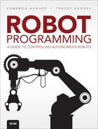
Kinematics is a branch of mechanics used to describe the motion of points, objects, and groups of objects without considering what caused the motion. So kinematics can be used to describe the motion of the robot arm or the motion of the robot. Planar kinematics (PK) is motion in a plane or a 2D space. It can be used to describe the displacements of two points by means of rotation or translation. A robot moving across an environment is on a plane unless the robot falls off a table or a cliff. PK can be used to calculate the rotations of the motors used to move the robot on the plane. It can also be used to translate the position of an end-effector in 2D space (see Figure 7.27).
Kinematics used for robot arm manipulation is forward and inverse kinematics, but both areas have a 3D and 2D. We briefly discuss 2D (planar). Forward kinematics answers the first question:
How can we calculate the angles of joints to position the end-effector?
Forward kinematics is used to calculate the position of an end-effector from the angle positions of the joints. So for a robot arm with 2 DOF, where servo 1 (the shoulder) and servo 2, the elbow, are at some angle, where is the end-effector? Inverse kinematics is used to calculate the position of the joints (servo 1 and servo 2) based on the position of an end-effector. So with the same robot arm with 2 DOF, with the end-effector at a given position, what is the angle position of servo 1 (the shoulder), and what is the angle position of servo 2, the elbow? Figure 7.28 contrasts these two situations.

Both are useful, but using them requires trigonometric and geometric equations. These equations can become complicated in a 3D space and where there are many joints. Once the equations are figured out, they must be translated into whatever language is being used to program the robot. Let’s use planar kinematics to figure out the angles of the servo for the Robot arm 1. Figure 7.29 shows how the equations were derived.

So given the length of the arm and the desired location for the end-effector, the angle for the servo can be calculated. Listing 7.10 contains a BURT Translation to derive the angle for a servo. It shows the pseudocode and the partial C++ code translation.
BURT Translation Listing 7.10 Robot Arm 1 Inverse Kinematics
BURT Translation INPUT ![]()
Softbot Frame
Name: ServoMotor
Parts:
Motor Section:
1 servo motor
Actions:
Given the length of the robot arm and the desired x,y location of
the end-effector,
Step 1: Square the x and y values
Step 2: If the Square root of the sum of squared x and y is less than
the length of the arm
Step 2:1: Take the arc tangent of x, y.
Step 2:2: Use this value for the angle of the servo.
Tasks:
Test the servo motors by controlling their speed.
End Frame
BURT Translations Output: Java Implementations ![]()
...
300 SquaredX = Math.pow(X,2);
301 SquaredY = Math.pow(Y,2);
302 if(ArmLength >= Math.sqrt(SquaredX + SquaredY))
303 {
304 ArmAngle = math.atan2(X,Y);
305 }
306 ...
For a 2D 2 DOF robot arm, another procedure is used. Figure 7.30 shows how the equations are derived.

So given the length of the two links and the desired location for the end-effector, the angle for the servos can be calculated. The complete code listing for this BURT Translation can be viewed or downloaded from our website: www.robotteams.org/intro-robotics.
What’s Ahead?
In this chapter, we talked about how to program different types of motors. In Chapter 8, “Getting Started with Autonomy: Building Your Robot’s Softbot Counterpart,” we will discuss how you start to program your robot to be autonomous.