
6. Programming the Robot’s Sensors
Robot Sensitivity Training Lesson #5
A robot can sense when you are mistaken.
For a mobile robot, having some type of vision is critical. A mobile robot needs to avoid obstacles; determine its location and the distance to objects; and detect, recognize, and track objects using a multitude of sensors such as infrared, ultrasonic, cameras, image sensor, light, color, and so on.
Robot vision is a complicated topic and beyond the scope of this book. But a robot may not need a full vision system; it may require only a few of these capabilities based on the scenario and situation it is programmed for. In this chapter we focus on programming sensors that play some part in the robot’s capability to “see”—that is, to perceive or detect as if by sight.
![]() Note
Note
We talked about senses and sensors at the beginning of Chapter 5, “A Close Look at Sensors.” We made the distinction between the sense, sight, and the organ (eyes for humans and a bunch of sensors for robots).
For a robot to see it uses
![]() Color/light sensors
Color/light sensors
![]() Ultrasonic/infrared sensors
Ultrasonic/infrared sensors
![]() Camera, image sensors
Camera, image sensors
Table 6.1 lists these sensors and how they assist in the robot’s capability to see.

Using the Color Sensor
A color sensor detects the color of objects. It is made of two simple components: an LED and a photo-resistor that is sensitive to light. The LED projects a light beam onto a target object, and the photo-resistor measures the reflected light off the object. This is called reflective color sensing. When the light beams hit the target (incident light), three things can happen to incident light:
![]() Reflection: A portion is reflected off the surface of the target.
Reflection: A portion is reflected off the surface of the target.
![]() Absorption: A portion is absorbed by the target surface.
Absorption: A portion is absorbed by the target surface.
![]() Transmission: A portion is transmitted.
Transmission: A portion is transmitted.
The amount of reflection and absorption is based on properties of the object. The reflected light is what is sensed.
There are two types of reflection—diffuse and specular—and both contribute to what the detector senses. The diffuse reflection carries the most useful information about the surface color, but varying specular reflection can negatively affect the performance of the sensor.
Mostly specular reflection is almost constant for a given target and could be factored out from the readings. The material of the object determines the amount of diffuse and specular reflectance. A matte surface has more diffuse than specular reflectance, and a glossy finish has more specular reflectance. Figure 6.1 (a) shows incident light (from the LED), diffuse, and specular reflections, (Reflection, absorption, and transmission are all identified.) The intensity of the reflected wavelengths is analyzed to figure out the surface color of the object. For example, if a color sensor emits a red LED on a ball, how is color detected? The sensor actually records the intensity reflected off the object. So, if the ball is red, the ball reflects back high intensity of red indicating the surface is in fact red. If the ball is blue, the red reflected back would not be very intense because most of the light would be absorbed by the object. The object is not red. (see Figure 6.1 [b]). But what if the ball is not a primary color (red, blue, green)?

Figure 6.1 (a) The incident light (from the LED), diffuse and specular reflections, (b) shows how color of object is detected based on specular light
What if the color is orange or yellow; how is the color detected? An orange ball is closer to red in the color spectrum than the yellow ball, so some red light would be reflected back. So for all the colors the sensor is designed to detect, it would report the color closest to it theoretically. The sensor may not be able to detect these colors at all returning an incorrect value. On the less sensitive end, color sensors detect only four or six colors; others can detect 16 or 18 colors under good lighting conditions. Figure 6.2 shows what colors are detected based on a color spectrum.

A typical color sensor has a high-intensity white LED that projects modulated light on the target object. Other sensors have RGB LEDs. With the white LED, the reflection from the object is analyzed for the constituent red, green, and blue (RGB) components and intensities. In memory, the sensor has all the ranges of RGB for all the colors it can recognize. The level of reflected light is compared to the value stored in the sensor’s memory. If the value is within a specified range, the sensor recognizes that color.
Color sensors combine the signal over the entire area of the light spot on the target object or field of view (FOV). So, if within the FOV there are two colors, the sensor sees the combination of the colors rather than each separate color. Color normalization removes all intensity values from the image while preserving color values. This has the effect of removing shadows or lighting changes on the same color pixels.
Color Sensor Modes
Color sensors can be set for different modes, and these modes report different aspects of the reading. For certain modes, the LED may or may not be used. Modes are made available via the API being used. Some examples of color sensor modes, described in Table 6.2, are
![]() Color ID
Color ID
![]() RGB
RGB
![]() Ambient light level
Ambient light level
![]() Light intensity level
Light intensity level
![]() Reflected light intensity
Reflected light intensity
![]() Calibration minimum and maximum
Calibration minimum and maximum

Detection Range
The object should be as close as possible to the sensor to detect its color. Many recommend that the sensor be placed close at an angle over the target object so the reflected LED does not affect the photo-resistor. This is true for inexpensive sensors and may not be practical for a given scenario for the robot though.
![]() Note
Note
Sensors have a minimum and a maximum range for accurate readings, but sometimes manufacturers do not list the maximum range.
The sensor takes an average of the entire FOV, so for the most precise results it is good to keep this field of view minimized.
A far-away reading may be desirable, for example, tracking the color of an object as the robot and color sensor move closer to the object. It may be necessary to track the color changes, for example, from a white color to an FOV that is an average of two or more colors and then back to a solid color as its target. The detection range should be specified in the manufacturer’s datasheet of the sensor. Again, even with the color sensor, the range is affected by the use of the sensor in the application.
![]() Tip
Tip
Remember, as the object is farther away from the LED, the FOV increases in size.
Lighting in the Robot’s Environment
What attributes of the environment can prevent the robot’s sensors from being accurate? Ambient light is one of the biggest factors that can sabotage color readings. Ambient light includes any additional light in the environment that can affect the way a color appears. It’s always present, and it can change the readings the robot receives at 8 a.m. compared to 8 p.m., or on one side of the room compared to the other side of the room.
![]() Caution
Caution
It’s of the utmost importance that ambient light does not affect the quality of the sensors, or readings can end up being wildly divergent and inaccurate resulting in inconsistent and inferior results.
The reflected light from the LED affecting the photo-resistor is considered ambient light as well. Shielding the sensor is a way to protect the photo-resistor from ambient light and is commonly used on surveillance cameras. Shielding refers to surrounding the sensors with something to prevent ambient light from interfering with the readings. This is especially valuable if the robot’s environment has drastically different light settings (from well-lit to very dark).
![]() Tip
Tip
The effect of ambient light can be lessened by using calibrated values. These values can be considered a baseline for accurate readings. Errors or offsets can be calculated and used to increase the accuracy of new readings.
Calibrating the Color Sensor
The color sensor should be calibrated for a specific application to ensure that it provides the expected readings. Before using the sensor in the application, detect the color of a range of target object(s), record readings, and then make a chart of this data. So when sensing the same object (within the system), compare the new reading with the calibrated reading. Some APIs for sensors define methods to calibrate the color sensor. The color sensor is calibrated for the minimum and maximum, black and white, for a specific application.
Correcting errors in sensor readings may have to be calculated wherever a reading is made. Say that the birthday party is in a room with a lot of natural light on a partly cloudy day. That means clouds blowing over the sun can change the light in the environment while the party is going on. BR-1 must distinguish the cake plates on the table from the color of the tablecloth on the table. During the calibration phase, BR-1 measures an analog value of 98 for the gray tablecloth, 112 for the white plate, and then stores these values in memory. Now BR-1 is in use and has to detect the white plate, but the sensor readings are slightly different because of the lighting. A 108 not 112 reading for the white plate and 95 not 98 for the value of the tablecloth are measured. What does that mean? Is it detecting the plate?
Using the thresholding method, you add both calibrated numbers and then divide by 2 to find the average number. For example:
(98 + 112)/2 = 105 (threshold)
Anything above the threshold would be the white plate, and anything under would be the gray tablecloth.
If there three or four colors have to be distinguished, how is a threshold figured out? In that case, a similarity matching method can be used. The question becomes, how similar is each color to the calibrated value? Using similarity matching, calculate:
similarity = abs(new_reading – calibrating_reading)/calibrated_reading * 100
So:
gray tablecloth = (95 – 98)/98 * 100 = 3.06% difference
white plate = (108 – 112)/112 * 100= 3.5% difference
Since the 3.06% < 3.5%, making the gray tablecloth reading more similar to the calibrated value than the white plate, the BR-1 sees the tablecloth. This method can be used for any color and any number of colors, given calibration values are calculated beforehand. Look at color calibration as a way of showing the robot the difference between colors.
Programming the Color Sensor
In this section, we show BURT Translations for programming the HiTechnic color sensor using the EV3 microcontroller and the color sensor for the RS Media Robosapien. Listing 6.1 is the BURT Translation for programming the HiTechnic color sensor using the leJOS API HiTechnicColorSensor class. Burt’s Translation Listing 6.1 shows the softbot frame for detecting a color and the Java code translation. This is the main line to test the color sensor and perform some basic operations.
BURT’s Translation Listing 6.1 Unit2’s Color Sensor Test Softbot Frame
BURT Translation INPUT ![]()
Softbot Frame
Name: Unit2
Parts:
Sensor Section:
Color Sensor
Actions:
Step 1: Initialize and perform any necessary calibration to the color sensor
Step 2: Test the color sensor
Step 3: Report the detected color, modes, sample size and content
Tasks:
Test the color sensor and perform some basic operations.
End Frame
BURT Translations Output: Java Implementations ![]()
32 public static void main(String [] args) throws Exception
33 {
34 softbot5 SensorRobot = new softbot5();
35 SensorRobot.testColor();
36 SensorRobot.closeLog();
37 }
38
In line 34, the softbot SensorRobot is declared. Three functions/methods are then called. We discuss the constructor and SensorRobot.testColor(). Listing 6.2 shows the code for the constructor.
Listing 6.2 The Constructor for the SensorRobot Object
1 public softbot5() throws Exception
2 {
3 Log = new PrintWriter("Softbot5.log");
4 ColorVision = new HiTechnicColorSensor(SensorPort.S2);
5 }
In line 4, a HiTechnicColorSensor object is declared. SensorPort.S2 is the serial port used for this sensor. The BURT Translation in Listing 6.3 shows the testColor()softbot frame and Java implementation.
BURT Translation Listing 6.3 The testColor()softbot Frame and Java Implementation
BURT Translation INPUT ![]()
Softbot Frame
Name: Unit2
Parts:
Sensor Section:
Color Sensor
Actions:
Step 1: Test the color sensor by reporting mode name, color ID, mode,
name, and RGB mode and name.
Step 2: Get and report sample size and content of the sample.
Tasks:
Test the color sensor and perform some basic operations.
End Frame
BURT Translations Output: Java Implementations ![]()
6
7 public void testColor() throws Exception
8 {
9 Log.println("Color Identified");
10 Log.println("ColorID Mode name =
" + ColorVision.getColorIDMode().getName());
11 Log.println("color ID number = " + ColorVision.getColorID());
12 Log.println("Mode name = " + ColorVision.getName());
13 Log.println(" ");
14 Log.println("RGB Mode name =
" + ColorVision.getRGBMode().getName());
15 Log.println("RGB name = " + ColorVision.getName());
16
17 float X[] = new float[ColorVision.sampleSize()];
18 Log.println("sample size = " + ColorVision.sampleSize());
19 ColorVision.fetchSample(X,0);
20 for(int N = 0; N < ColorVision.sampleSize();N++)
21 {
22 Float Temp = new Float(X[N]);
23 Log.println("color sample value = " + Temp);
24 }
25 }
Here is the output for Listing 6.3:
Color Identified
ColorID Mode name = ColorID
color ID number = 2
Mode name = ColorID
RGB Mode name = RGB
color ID number = 2
RGB name = ColorID
sample size = 1
color sample value = 2.0
The color ID number returned was 2. which is blue. Table 6.3 shows the color index and names.

The HiTechnicColorSensor class defines several methods that return the color mode name and the color ID. There is also a SampleProvider class that stores the color ID value. To extract the color ID value from the sample, an array of floats is declared in line 17. It has the size of ColorVision.sample.size():
17 float X[] = new float[ColorVision.sampleSize()];
In line 19, the contents of the SampleProvider contain all the color ID values returned from the call to the ColorVision.getColorID() method
19 ColorVision.fetchSample(X,0);
The ColorVision.fetchSample(X,0) method accepts an array of floats and the offset. From the offset position, all the elements are copied to the array.
Lines 20 to 24 are used often. This loop reports all the values stored in the sample array:
20 for(int N = 0; N < ColorVision.sampleSize();N++)
21 {
22 Float Temp = new Float(X[N]);
23 Log.println("color sample value = " + Temp);
24 }
Digital Cameras Used to Detect and Track Color Objects
Color sensors are not the only device that can detect color. Digital cameras can be used to detect colors in a captured image. Considering that digital cameras can be small, they can be purchased as a component of a vision system for a robot or already embedded in the head of a robot.
Coupled with the digital cameras is an image sensor. This sensor is the device that converts the optical image into an electronic signal that serves as the “film” for the digital camera. They are sensitive to light and record the image. Each cell of the image is processed to gather all information to accurately re-create the image digitally. This image processing can also recognize colors of individual pixels. These devices can be used to detect color and perform object recognition (shape and color) to track that object. By using a camera, the object is detected from a stream of images. Detection means finding the colored object from one frame from a video stream. In this section, we discuss two color cameras: one embedded in Unit2 (RS Media Robosapien) and the Pixy vision sensor used by Unit1.
Tracking Colored Objects with RS Media
Tracking an object is the process of locating a moving or multiple objects over time using a camera. The idea is to detect the target objects in each consecutive video frame. Detection of the object can be difficult if the object(s) is moving fast relative to the camera. Some type of object recognition has to be performed to identify the targeting object in each frame. A number of object attributes can be used like size or shape, but the simplest one to use is color. The sensor has to be trained to recognize the object by letting it see the object, using the camera, so it can detect the color of the object. Once the target color of the object is detected in a frame, its location is accessed.
Unit2 is an RS Media Robosapien, a bipedal robot with a Linux kernel. It has several sensors and has an LCD screen. Figure 6.3 shows a diagram of the RS Media Robosapien, and Figure 6.4 shows its capability matrix in a LibreOffice spreadsheet. (LibreOffice is an open source office suite.)


BURT Translation in Listing 6.4 shows the pseudocode and Java fragment code translation for Unit2 to perform color object tracking. Listing 6.4 just contains the colorTrack() method.
BURT Translation Listing 6.4 The colorTrack() Method
BURT Translation INPUT ![]()
Softbot Frame
Name: Unit2
Parts:
Sensor Section:
Camera
Actions:
Step 1: Place in default position
Step 2: Put camera in tracking mode
Step 3: Tell camera to track a blue object
Step 4: Detect and track the object
Step 5: If the object was blue
Step 6: Wave the left arm
Step 7: Return to default position
Step 8: Tell camera to track a green object
Step 9: Detect and track the object
Step 10: If the object was green
Step 11: Wave the right arm
Step 12: Return to default position
Step 13: Tell camera to track a red object
Step 14: Detect and track the object
Step 15: If the object was red
Step 16: Continue to track
Step 17: Turn right 3 steps
Step 18: Turn left 3 steps
Step 19: Stop
Tasks:
Test the color sensor by tracking a colored object and then perform some movements.
End Frame
BURT Translations Output: Java Implementations ![]()
1 private void colorTrack()
2 {
3 boolean BlueInColor = false;
4 boolean RedInColor = false;
5 boolean GreenInColor = false;
6 boolean BlackInColor = false;
7 int Blue = 0;
8 int Red = 2;
9 int Green = 1;
10 int Black = 4;
11
12 Unit2.restoreDefaultPosition();
13 Unit2.VISION.track();
14 BlueInColor = Unit2.VISION.getTarget(Blue);
15 if(BlueInColor){
16 Unit2.LEFT_ARM.wave();
17 Unit2.waitUntilStop();
18 Unit2.restoreDefaultPosition();
19 }
20 GreenInColor = Unit2.VISION.getTarget(Green);
21 if(GreenInColor){
22 Unit2.RIGHT_ARM.wave();
23 Unit2.waitUntilStop();
24 Unit2.restoreDefaultPosition();
25 }
26 RedInColor = Unit2.VISION.getTarget(Red);
27 if(RedInColor){
28 Unit2.VISION.track();
29 Unit2.waitUntilStop();
30 Unit2.VISION.track();
31 Unit2.waitUntilStop();
32 Unit2.WALK.turnRight(3);
33 Unit2.waitUntilStop();
34 Unit2.WALK.turnLeft(3);
35 Unit2.waitUntilStop();
36 }
37 }
For Unit2 to track an object, the object has to be placed within 2.5 cm of the camera and be stationary for Unit2 to learn the color first. Once the color is learned, Unit2 can detect any object of that color. Unit2 tracks the object’s movements for 30 seconds and then it exits camera mode. Unit2 uses an infrared sensor to track the object within its range. It has a long and close range. To detect objects long range, it has to be within 24 inches from the sensor. At close range, an object has to be within 6 inches.
Unit2’s vision is activated in line 13 with a call to the Unit2.VISION.track() method. It detects an object of a specified color and tracks that object with a call to getTarget(). It is called three times to detect and track three different colored objects:
14 BlueInColor = Unit2.VISION.getTarget(Blue);
...
20 GreenInColor = Unit2.VISION.getTarget(Green);
...
26 RedInColor = Unit2.VISION.getTarget(Red);
...
The getTarget() method returns a true or false if the target color object is detected and tracked. If true, Unit2 performs a few movements.
The method Unit2.waitUntilStop(); is used several times. It is needed to make sure Unit2 has completed the previous task before attempting another task. This is used often. A robot may take several compute cycles or even several minutes to perform a task. If the robot depends on the previous task’s completion, using a wait is necessary. For example, if Unit2 has to travel to a location before it is to detect an object at that location, depending on the distance, it may take the robot several minutes to arrive at that location. If the robot immediately attempts to detect a color object before it arrives at the location, it may detect the wrong object or no object at all. At that point, all bets are off, and the robot fails to complete its tasks.
Tracking Colored Objects with the Pixy Vision Sensor
As mentioned earlier, simple vision (to recognize an object by its color and track its location) for a robot is a system composed of several components and sensors:
![]() Recognition or color detections (color sensor)
Recognition or color detections (color sensor)
![]() Distance or proximity detector (ultrasonic/infrared)
Distance or proximity detector (ultrasonic/infrared)
Use some image processing, and Voila! robot vision! RS Media has a nice vision system as we have discussed, but it comes up short in these ways:
![]() It’s embedded in a robot.
It’s embedded in a robot.
![]() It can detect a single colored object.
It can detect a single colored object.
![]() It does not provide information about the object.
It does not provide information about the object.
The Pixy vision sensor is a digital color camera device that tracks objects by color and reports information about the object. Pixy has a dual-core dedicated processor that sends useful information like width, height, and x y location to the microcontroller at 50 frames per second for an image with 640 × 400 resolution. So information on detected objects is updated every 20 ms. The more frames per second or ms, the more precise documentation of the position of the object.
The Pixy can be connected to UART serial, I2C, USB bus interfaces; output can be digital/analog; and it can use Arduino and LEGO microcontrollers. Pixy can detect seven different color objects and track hundreds of items of the target colors at once. Using color codes, colors can be customized beyond the seven primary colors. Color codes combine colors to create unique objects to be detected. Table 6.4 lists the attributes of the Pixy and RS Media vision cameras.

Training Pixy to Detect Objects
Training Pixy to detect an object is similar to training the RS Media camera. The object has to be held so many inches in front of the camera so it can detect the color of the object. Once trained, the Pixy can detect other objects of the same color. With the Pixy there are two ways to do this:
![]() Use the PixyMon program.
Use the PixyMon program.
![]() Use just the Pixy.
Use just the Pixy.
![]() Note
Note
We used the Pixy for training but also used the PixyMon program for configuration.
The Pixy has to be connected to the PC using a serial cable, and it must have a power supply. Run the PixyMon program to monitor what the camera sees. The Pixy sensor has an LED used to make sure the sensor recognizes the color and helps identify multiple objects to be detected. Once the button on the Pixy is pressed for 1 second, the LED sequences through several colors starting with white.
When the button is released, the camera is in light mode. The object should be held 6 inches to 20 inches in front of the lens in the center of the field of view. The LED should match the color of the object. For example, if the LED turns green when a green object is placed directly in front of Pixy, it has recognized that color. The LED flashes if successful and turns off if not successful. If successful, the button on the Pixy should be pressed and released; then the Pixy generates a statistical model of the colors in the object and stores them in flash. This statistical model is used to find objects of the same color.
If there are multiple objects to detect, each object must be associated with a signature, an identifier for the colors to be detected. Pixy’s LED flashes through a sequence of seven colors; each is a signature:
![]() Red
Red
![]() Orange
Orange
![]() Green
Green
![]() Cyan
Cyan
![]() Blue
Blue
![]() Violet
Violet
The first object is associated with Red (1), the second object is associated with Orange (2), and so on. The button is held until the desired color is flashed. PixyMon shows the video images of the sensor. As an object color is identified, the object is pixelated with that color (as shown in Figure 6.5).

Figure 6.5 Screen capture of PixyMon where Pixy recognizes an object. Also shown is a picture of actual objects.
Programming the Pixy
Once the Pixy has been trained on the color objects it is to detect, it can be used to detect and track objects. Listing 6.5 is the BURT Translation that shows the pseudocode and Java code translation to perform color object tracking by the Pixy camera mounted on Unit1.
BURT Translation Listing 6.5 The Pixy to Perform Color Object Tracking
BURT Translation INPUT ![]()
Softbot Frame
Name: Unit1
Parts:
Sensor Section:
Vision Sensor
Actions:
Step 1: Initialize the sensor.
Step 2: Detect and track objects.
Step 3: If any objects were detected
Step 4: Report the number of objects, width, height, xy location and color.
Tasks:
Test the vision sensor, track an object, and report basic information about an object.
End Frame
BURT Translation Output: Java Implementations ![]()
1 //
2 // begin license header
3 //
4 // This file is part of Pixy CMUcam5 or "Pixy" for short
5 //
6 // All Pixy source code is provided under the terms of the
7 // GNU General Public License v2 (http://www.gnu.org/licenses/gpl-2.0.html).
8 // Those wishing to use Pixy source code, software and/or
9 // technologies under different licensing terms should contact us at
10 // [email protected]. Such licensing terms are available for
11 // all portions of the Pixy codebase presented here.
12 //
13 // end license header
14 //
15 // This sketch is a good place to start if you're just getting started with
16 // Pixy and Arduino. This program simply prints the detected object blocks
17 // (including color codes) through the serial console. It uses the Arduino's
18 // ICSP port. For more information go here:
19 //
20 // http://cmucam.org/projects/cmucam5/wiki/Hooking_up_Pixy_
to_a_Microcontroller_(like_an_Arduino)
21 //
22 // It prints the detected blocks once per second because printing all of the
23 // blocks for all 50 frames per second would overwhelm the Arduino's serial
port.
24 //
25
26 #include <SPI.h>
27 #include <Pixy.h>
28
29 Pixy MyPixy;
30
31 void setup()
32 {
33 Serial.begin(9600);
34 Serial.print("Starting...
");
35 MyPixy.init();
36 }
37
38 void loop()
39 {
40 static int I = 0;
41 int Index;
42 uint16_t Blocks;
43 char Buf[32];
44
45 Blocks = MyPixy.getBlocks();
46 if(Blocks)
47 {
48 I++;
49 if(I%50 == 0)
50 {
51 sprintf(Buf, "Detected %d:
", Blocks);
52 Serial.print(Buf);
53 for(Index = 0; Index < Blocks; Index++)
54 {
55 sprintf(Buf, " Block %d: ", Index);
56 Serial.print(Buf);
57 MyPixy.Blocks[Index].print();
58 if(MyPixy.Blocks[Index].signature == 1){
59 Serial.print("color is red");
60 }
61 if(MyPixy.Blocks[Index].signature == 2){
62 Serial.print("color is green");
63 }
64 if(MyPixy.Blocks[Index].signature == 3){
65 Serial.print("color is blue");
66 }
67 }
68 }
69 }
70 }
The Pixy sensor is declared in line 29 and is a Pixy object:
29 Pixy MyPixy;
The object MyPixy is initialized in the setup() function. The information about the detected objects is stored in the structure Blocks declared in Line 42 of type uint16_t.
In the loop() function, the getBlocks() method called in Line 45 returns the number of objects recognized in front of the video camera lens. If there are any recognized objects, the information for each object is reported. The Pixy is continuously detecting eight objects; the program is reporting the information for each object.
As mentioned earlier, Pixy processes 50 frames a second, and in each frame can be many objects that can be recognized. So information for every frame is not reported. Only when the I is divisible by 50, the number of Blocks is reported from a given frame.
The for loop cycles through the array block of Pixy objects recognized in the frame. In Line 57:
57 MyPixy.Blocks[Index].print();
The print() method reports the information for a particular Pixy object. The pieces of information stored for each object are:
![]() signature
signature
![]() x
x
![]() y
y
![]() width
width
![]() height
height
The print() method reports this information. Each piece of information can also be reported using the attributes directly:
MyPixy.Blocks[Index].signature
MyPixy.Blocks[Index].x
MyPixy.Blocks[Index].y
MyPixy.Blocks[Index].width
MyPixy.Blocks[Index].height
Each attribute is of type uint16_t. By using signature, the color can also be reported. The Pixy was trained to detect three colors:
![]() signature 1: Red
signature 1: Red
![]() signature 2: Green
signature 2: Green
![]() signature 3: Blue
signature 3: Blue
Depending on the signature, the correct color is reported:
58 if(MyPixy.Blocks[Index].signature == 1){
59 Serial.print(" color is red");
60 }
61 if(MyPixy.Blocks[Index].signature == 2){
62 Serial.print(" color is green");
63 }
64 if(MyPixy.Blocks[Index].signature == 3){
65 Serial.print(" color is blue");
66 }
A Closer Look at the Attributes
Figure 6.6 shows the field of view for the Pixy sensor.

The objects detected are in the field of view of the camera. The horizontal FOV is 75° and the vertical FOV is 47°. With a 75° FOV, there is a maximum viewing distance of 10 feet. To extend the detection distance, a lens with a longer focal length can be used, but this would narrow the field of view. Pixy detects the xy location of the foci of the object. The minimum and maximum values for the width, height, x, and y attributes are listed in Table 6.5.

Ultrasonic Sensor
The ultrasonic sensor is a range finding sensor, an important component of a robot vision system. It measures the distance of an object from the actual sensor by generating sound waves that are not human audible, above 18 kHz. It then listens for the sound to be reflected back off objects in its sensing range. The time it takes to transmit and then receive the reflected wave tells us the time it takes for the wave to travel the distance. This time can then be converted to a distance measurement.
Many ultrasonic sensors are two in one; they transmit a signal and receive a signal. The transmitter sends high-frequency sound waves, and the receiver evaluates the echo received back. The sensor measures the time it takes to send the signal and receive the echo. This measurement is then converted to standard units (SI) such as inches, meters, or centimeters. The signal is really a sound pulse that stops when the sound returns. The width of the pulse is proportional to the distance the sound traveled, and the sound frequency range depends on the sensor. For example, industrial ultrasonic sensors operate between 25 kHz and 500 kHz.
The sensing frequency is inversely proportional to distance sensed. A 50 kHz sound wave may detect an object at 10 m or more; a 200 kHz sound wave is limited to detecting objects at about 1 m. So detecting objects farther away requires a lower frequency, and the higher frequencies are for objects closer to the sensor. Typical low-end ultrasonic sensors have frequencies of 30 kHz to 50 kHz. The ultrasonic sensors we use have a frequency of around 40 kHz and a sensing range of 2 to 3 meters.
Ultrasonic Sensor Limitations and Accuracy
The sensor emits a cone-shaped beam, and the length of the cone is the range of the sensor. It defines the FOV. If something is within the ultrasonic sensor’s FOV, the sound waves are reflected off the object. But if the object is far away from the sensor, the sounds waves decrease the farther it travels, which affects the strength of the echo. This can mean that the receiver may not detect the echo or the reading may become unreliable. This is also true for objects at various extremes of the FOV. An ultrasonic sensor has a blind zone located nearest the face of the transmitter. This is an area where the sensor is unusable. This is the distance from the sensor where the beam hits a target and returns before the sound wave transmission is complete. The echo is not reliable. The outer edge of the blind zone is considered the minimum range an object can be from the transmitter. It is only a few centimeters.
What about objects to either side of the sensor? Will they be detected? It depends on the directivity of the sensor. The directivity is a measurement of the directional characteristics of the sound source generated by the transmitter. This measures how much sound is directed toward a specific area. Figure 6.7 (a) illustrates a typical sound energy radiation pattern’s FOV at 50 kHz with sound decibels normalized on the x-axis. At various points in the pattern the distance and the level of decibels registered at that point can be determined. An object in the line of sight from the sound source registers the best performance at the maximum range. The lobes on each side show a shorter range.
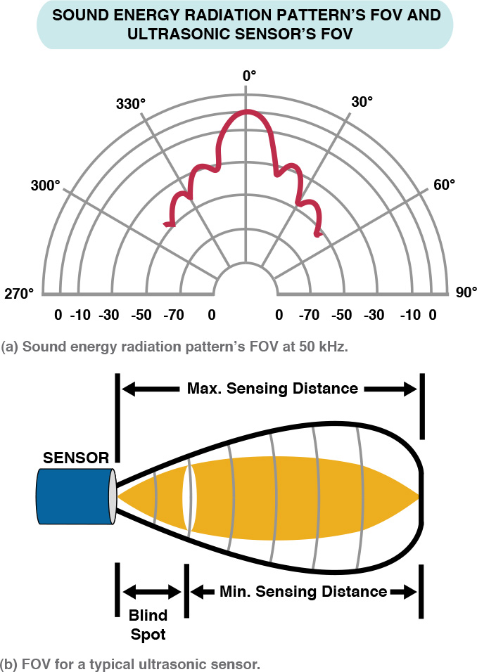
Figure 6.7 A typical sound energy radiation pattern’s FOV at 50 kHz; (b) FOV for an X ultrasonic sensor
![]() Note
Note
Objects measured above the maximum distance return a weak signal, which may also be unreliable.
Figure 6.7 (b) shows the FOV for an X ultrasonic sensor. Objects are located indicating its level of detection. As the distance increases the FOV also decreases to less than half at the maximum range.
When dealing with the limitations and accuracy of this sensor, directivity and ranges are not issues. Other limitations have to do with the material of the object and the angle the object is to the sensor and how that affects its accuracy. The accuracy of the sensor is how close the actual value is to the expected value. This calculation is in Chapter 5, Table 5.8 where A is the actual or measured value and E is the expected or true value. So an object at 60 cm distance from the ultrasonic sensor should produce a reading of 60 cm.
The accuracy of the EV3 ultrasonic sensor is documented at –/+1 cm. with a range of 3 cm to 250 cm. If the material surface absorbs sound, such as foam, cotton, rubber, this makes detecting more difficult compared to the object’s surface made of more reflective materials such as plastic, steel, or glass. Sound absorbent materials can actually limit the maximum sensing distance. When using such objects, accuracy may be less than ideal or better by a few centimeters. The accuracy level should be tested for the application. The ultrasonic sensor performs best when the sensor sits high on the robot avoiding the sound waves hitting the floor and perpendicular to the object.
Figure 6.8 shows the various limitations of an ultrasonic sensor. The diagram shows the transmitter sending out a sound wave (or ping) that is reflected off an object (or wall). The first diagram (a) shows the sound wave returning an accurate reading. The object is directly in front of the sensor with the sensor parallel to the object and the beam hitting the object. The second diagram (b) illustrates foreshortening when the sensor is at an angle and the reading does not reflect an accurate distance. The pulse is wider (took a longer time to return because the distance has increased) than the original pulse. The third diagram (c) illustrates specular reflection when the wave hits the surface of the object or wall at an acute angle and then bounces away. The echo is not detected by the receiver at all. Odd-shaped objects can also reflect the sound waves in this way. The crosstalk is when multiple ultrasonic sensors in the system are in use simultaneously and all use the same frequency. The signals may be read by the wrong receiver as illustrated in (d). But this may be desirable where some sensors are in listening mode.

Figure 6.8 Various limitations of an ultrasonic sensor due to sound waves (a) accurate reading, (b) foreshortening, (c) specular reflection, (d) crosstalk
Regardless of the size of the object—a wide large object or a skinny one—with a wide cone and the way sound waves spread out, there would be no distinction between them.
Consider comparing an ultrasonic and an infrared long-range sensor that detects an object at 50 cm. The infrared sensor also has an emitter and a receiver, but it uses a single beam of IR light and triangulation to detect the distances of objects.
In Figure 6.9(b), using a narrow beam and a 10° FOV, an object can be located if the sensor is directly in its line of sight, 5° in either direction. Using this narrow beam it can detect doorways (no reading) where the ultrasonic sensor (Figure 6.9(b)) may detect the door frame. They can also be used to detect the width of objects. A robot equipped with both types of proximity sensors could better navigate paths through doorways and around a room with different sized obstacles. Some ultrasonic sensors can detect up to eight objects (returning multiple readings), but not all software avails the user of this option.

Figure 6.9 An ultrasonic sensor detects a sound wave that is reflected off a target (a). An infrared sensor, a single beam utilizing triangulation is reflected off a target is detected.
The harder the object is to detect, whether its size, surface, or distance, the shorter the maximum sensing distance can be. Larger objects are easier to detect than smaller ones. Objects with smooth or polished surfaces reflect sound better than surfaces that are soft and porous, making them easier to detect. This is shown in Figure 6.10.

Modes of the Ultrasonic Sensor
An ultrasonic sensor can be set to perform in different modes. The modes available depend on the manufacturer, the developer of libraries, and the software used to take advantage of its capabilities. An ultrasonic sensor can continuously send out sound waves or transmit a single ping and take a reading.
In continuous mode, the sound waves are sent out periodically at a regular interval. If an object is detected, the reading is stored. In single ping mode, the sensor sends out a single ping and takes a reading. If an object is detected, that reading is returned. Some sensors in this mode can detect multiple objects with a single ping where each reading is stored in a data structure like an array with the closet object reading in the first position. Active sensor mode for the ultrasonic sensor is the normal functioning of the sensor where it listens for the echo of the wave it transmitted. In passive mode, the sensor does not transmit. It just listens for echoes of other ultrasonic sensors. Table 6.6 lists the various ultrasonic sensor modes with a brief description.

Sample Readings
The sample for the ultrasonic sensor is the pulse width that represents time in the microseconds it took for the sound wave to reach the object and reflect back to the receiver. Once the reading is returned and stored it has to be converted into standard units (SI). We are interested in distances, so the standard units are distance measurements such as inches, feet, centimeters, and meters. It is necessary to convert microseconds into these standard units. As stated earlier, the width of the pulse is proportional to the distance the sound wave traveled to reach the object. The units for speed of sound are measured in distance per unit of time:
![]() 13503.9 inches per second
13503.9 inches per second
![]() 340 meters per second
340 meters per second
![]() 34000 centimeters per second
34000 centimeters per second
In microseconds, sound travels at 29 microseconds per centimeter. So if our ultrasonic sensor returned 13340 microseconds, to determine how far the sound wave traveled, this calculation has to be performed:
13340 ms / 2 = 6670 ms
It is divided because the reading is a round trip and we want just the one-way distance.
6670 ms / 29 ms/cm = 230 cm = 2.3 m
So the object detected was 230 cm away, or 2.3 m away, from the sensor. This can be easily converted to inches if needed. So who performs this calculation? Some sensor libraries have functions that perform this calculation for you as a method for a built-in sensor or base sensor class. If not provided, the conversion function or calculation has to be written for the sensor class.
Data Types for Sensor Reading
![]() Tip
Tip
An int should be used to store the microseconds or measurement reading returned. The microseconds can be a very large number. Once converted, the value should be stored as a float if decimal precision is required.
Calibration of the Ultrasonic Sensor
There are many different ways to calibrate an ultrasonic sensor to make sure the sensor is working properly and consistently produces the most accurate readings. Sensors should be tested to see how they perform in the system under development. Calibrating an ultrasonic sensor can be as simple as taking multiple readings of an object at the same distance to make sure the same readings are returned.
If the robot has multiple ultrasonic sensors, making one active and the other passive (crosstalk) allows each sensor to test the other. But the concern for accuracy also includes how the sensor’s environment affects its performance. Some libraries have defined calibration methods for the ultrasonic sensor. If not, using continuous and ping modes in combination or separately will suffice.
For our birthday party scenario, consider the objects BR-1 may use its ultrasonic sensor to detect:
![]() Birthday cake
Birthday cake
![]() Plates on a table
Plates on a table
![]() Cups on a table
Cups on a table
A birthday cake has a soft, porous surface. It may be difficult to detect the cake at farther ranges. The plates and cups (if they are made of glass or ceramic) have a reflective surface, but the plates are close to the table’s surface. The good thing for the cake is there is no need to attempt to detect the cake at a long distance; it is on the table. So calibrating the ultrasonic sensor for this scenario requires that the sensor can detect these items at close range with varying surface types as shown in Figure 6.11.

Air temperature, humidity, and air pressure can also affect the speed of sound waves. If the ultrasonic sensor is to work in an environment with fluctuating temperature, for example, this may affect the readings. Molecules at higher temperatures have more energy and can vibrate faster, causing sound waves to travel more quickly. The speed of sound in room temperature air is 346 meters per second, much faster than 331 meters per second at freezing temperatures.
Accuracy concerning FOV, objects of different sizes, odd shapes, or surfaces requires different types of testing and calibration than for temperature and air pressure. A test plan should be created and measurements should be recorded and compared to expected values. Table 6.7 shows a sample testing of an ultrasonic sensor comparing the expected to the actual reading of the sensor on several objects at different locations.

Programming the Ultrasonic Sensor
In this section, we show BURT Translations for programming ultrasonic sensors for the EV3 and Arduino Uno microcontrollers. To program an ultrasonic sensor, the sensor must be initialized with the appropriate information and be prepared to receive input from its environment. The ultrasonic sensor may also require some type of calibration in the form of testing, validating, correcting, estimating the error, or determining the standards values for your system.
Listing 6.6 is the BURT Translation for programming the EV3 ultrasonic sensor. This BURT Translation shows the pseudocode for the actions of the ultrasonic sensor and the Java code translation. This is the main line to test the ultrasonic sensor to perform some basic operations. Listing 6.6 is a Softbot Frame for the BURT Translation for Unit1’s ultrasonic sensor test and the Java code translation.
BURT Translation Listing 6.6 Softbot Frame for Unit1’s Ultrasonic Sensor Test
BURT Translation INPUT ![]()
Softbot Frame
Name: Unit1
Parts:
Sensor Section:
Ultrasonic Sensor
Actions:
Step 1: Initialize and perform any necessary calibration to the
ultrasonic sensor
Step 2: Test the ultrasonic sensor
Step 3: Report the distance and the modes
Tasks:
Test the ultrasonic sensor and perform some basic operations.
End Frame
BURT Translation Output: Java Implementations ![]()
49 public static void main(String [] args) throws Exception
50 {
51 softbot SensorRobot = new softbot();
52 SensorRobot.testUltrasonicPing();
53 SensorRobot.getUSModes();
54 SensorRobot.closeLog();
55 }
In line 51, the softbot SensorRobot is declared. Three functions/methods are then called:
SensorRobot.testUltrasonicPing()
SensorRobot.getModes()
SensorRobot.closeLog()
In Listing 6.7 is the Java code for the softbot constructor.
Listing 6.7 The Softbot Constructor
8 public softbot() throws Exception
9 {
10 Log = new PrintWriter("Softbot.log");
11 Vision = new EV3UltrasonicSensor(SensorPort.S3);
12 Vision.enable();
13 }
Sensor initialization occurs in the constructor along with any necessary calibration. In line 11, like with all other sensors, the ultrasonic sensor is initialized with the sensor port and then enabled (line 12). No calibration was needed considering only a simple reading was to be performed.
BURT Translation in Listing 6.8 contains the “Softbot Frame” and Java translation for testUltrasonicPing().
BURT Translation Listing 6.8 The testUltrasonicPing() Method
BURT Translation INPUT ![]()
Softbot Frame
Name: Unit1
Parts:
Sensor Section:
Ultrasonic Sensor
Actions:
Step 1: Measure the distance to the object in front of the sensor
Step 2: Get the size of the sample
Step 3: Report the size of the sample to the log
Step 4: Report all sample information to the log
Tasks:
Ping the ultrasonic sensor and perform some basic operations.
End Frame
BURT Translations Output: Java Implementations ![]()
15 public SampleProvider testUltrasonicPing() throws Exception
16 {
17 UltrasonicSample = Vision.getDistanceMode();
18 float Samples[] = new float[UltrasonicSample.sampleSize()];
19 Log.println("sample size =" + UltrasonicSample.sampleSize());
20 UltrasonicSample.fetchSample(Samples,0);
21 for(int N = 0; N < UltrasonicSample.sampleSize();N++)
22 {
23 Float Temp = new Float(Samples[N]);
24 Log.println("ultrasonic value = " + Temp);
25 }
26 Log.println("exiting ultrasonic ping");
27 return UltrasonicSample;
28 {
Listing 6.8 shows the Java code for the testUltrasonicPing() method. Vision is an EV3UltrasonicSensor object. The sensor continuously sends out pulses. In line 17, the Vision.getDistanceMode() method listens for the echo and returns the measurement of the closest object to the sensor in meters. This value is stored in SampleProvider UltrasonicSample. In line 18, an array of floats (Samples) is declared of a size the number of samples. In line 20, the fetchSample() method assigns all elements in UltrasonicSample to Samples starting at offset 0. All values are then written to the log.
Listing 6.9 is the BURT Translation for the getUSModes() method.
BURT Translation Listing 6.9 The getUSModes() Method
BURT Translation INPUT ![]()
Softbot Frame
Name: Unit1
Parts:
Sensor Section:
Ultrasonic Sensor
Actions:
Step 1: Create an array that will hold all the possible mode names.
Step 2: Store the mode names in the array.
Step 3: Report the mode names to the log.
Tasks:
Report the mode names for the ultrasonic sensor.
End Frame.
BURT Translations Output: Java Implementations ![]()
31 public int getUSModes()
32 {
33 ArrayList<String> ModeNames;
34 ModeNames = new ArrayList<String>();
35 ModeNames = Vision.getAvailableModes();
36 Log.println("number of modes = " + ModeNames.size());
37 for(int N = 0; N < ModeNames.size();N++)
38 {
39 Log.println("ultrasonic mode = " + ModeNames.get(N));
40 }
41 return(1);
42 }
Here is the report generated by Unit1:
sample size = 1
ultrasonic value = 0.82500005
exiting ultrasonic ping
number of modes = 2
ultrasonic mode = Distance
ultrasonic mode = Listen
There was only one sample. The value of the sensor reading was 0.82500005 m. The EV3 ultrasonic sensor has two modes, Distance and Listen. In Distance mode, the sensor sends out a pulse, and listens for the echo to return the value. In Listen mode, the sensor does not send out a pulse or take a reading. It returns a value indicating other ultrasonic sensors are present.
Listing 6.10 contains the BURT Translation Input for taking readings of ultrasonic sensorsconnected to an Arduino Uno microcontroller.
BURT Translation Input Listing 6.10 Softbot Frame for Ultrasonic Sensor readings.
BURT Translation INPUT ![]()
Softbot Frame
Name: Unit1
Parts:
Sensor Section:
Ultrasonic Sensor
Actions:
Step 1: Set communication rate for the sensor
Step 2: Set the mode as Input or Output for the appropriate pins
Step 3: Send out a pulse
Step 4: Take a reading
Step 5: Convert the reading to centimeters
Step 6: Report the distance
Tasks:
Take a reading with the ultrasonic sensor and report the distance
End Frame
The next three programs are BURT Translation Outputs for three different ultrasonic sensors, each connected to an Arduino Uno microcontroller:
![]() HC-SR04
HC-SR04
![]() Parallax Ping)))
Parallax Ping)))
![]() MaxBotix EZ1
MaxBotix EZ1
Each ultrasonic sensor has important differences, which are discussed. An Arduino program (called a sketch) has two functions:
![]()
setup()
![]()
loop()
The setup() function is like a constructor. It is used to initialize variables, set pin modes, and so on. It only runs once after each time the Arduino board is powered up or reset. After the setup() function, the loop() loops indefinitely. So whatever is defined in the loop function is consecutively executed forever or until it is stopped. Listing 6.11 contains the BURT Translation C++ output for Ultrasonic Sensor 1, HC-SR04.
BURT Translation C++ Output Listing 6.11 C++ Translation for HC-SR04
BURT Translations Output: C++ Implementations ![]()
1 const int EchoPin = 3;
2 const int PingPin = 4;
3
4 void setup()
5 {
6 pinMode(PingPin,OUTPUT);
7 pinMode(EchoPin,INPUT);
8 Serial.begin(9600);
9 }
10
11 void loop()
12 {
13 long Cm;
14 Cm = ping();
15 Serial.println(Cm);
16 delay(100);
17 }
18
19 long ping()
20 {
21 long Time, Distance;
22 digitalWrite(PingPin, LOW);
23 delayMicroseconds(2);
24 digitalWrite(PingPin, HIGH);
25 delayMicroseconds(10);
26 digitalWrite(PingPin, LOW);
27 Time = pulseIn(EchoPin, HIGH);
28 Distance = microToCentimeters(Time);
29 return Distance;
30 }
31
32 long microToCentimeters(long Micro)
33 {
34 long Cm;
35 Cm = (Micro/2) / 29.1;
36 return Cm;
37 }
Figure 6.12 shows a diagram of this sensor.

The HC-SR04 has four digital pins:
![]() Vcc: 5V Supply
Vcc: 5V Supply
![]() Trig: Trigger Pulse Input
Trig: Trigger Pulse Input
![]() Echo: Echo Pulse Output
Echo: Echo Pulse Output
![]() GND: 0V Ground
GND: 0V Ground
The Vcc pin is connected to a 5V power source, and the GND is connected to the ground on the Arduino Uno board. We are interested in two pins:
![]() One used for pulse output. (
One used for pulse output. (PingPin is used to send out a pulse.)
![]() One used for pulse input. (
One used for pulse input. (EchoPin is used to read the pulse.)
The pinMode() function sets the specified digital pin to be used for either input or output. The pinMode() function accepts two parameters:
![]()
pin
![]()
mode
The pin is the number of the Arduino pin whose mode is to be set, and mode is the mode to be set. The mode is either INPUT or OUTPUT. A pin set to INPUT mode accepts input from whatever the pin is connected to (in this case an ultrasonic sensor), open to accept an electrical pulse. It is described as being in a high-impedance state. A pin set to OUTPUT mode sends out a pulse and is described as being in a low-impedance state. In line 6, the PingPin (pin 4) is set to be the OUTPUT pin, and in line 7 the EchoPin (pin 3) is set to be the INPUT pin. This means pin 4 is used to send out the ping to locate an object, and pin 3 is used to receive the reading if the ping is reflected off an object. Serial.begin(9600) sets the communication rate to 9600 in line 8.
The loop() function is defined in line 11 through 17. The ping() function is called in line 14 and the reading is returned. In line 15 the reading is reported. The ping() and microToCentimeters() functions are both user-defined functions. The ping() function sends out the pulse, takes a reading, and sends the reading (in microseconds) to the converted to centimeters. In ping()function:
![]()
digitalWrite()
![]()
delayMicroseconds()
function pairs are called twice. The digitalWrite() function writes a HIGH or LOW value to the specified digital pin. The PingPin has been configured as OUTPUT set with pinMode() in setup(); its voltage is set to LOW and then there is a 2 microsecond delay. The same PingPin is set to HIGH, meaning a 5V pulse is sent out and then there is a 10 microsecond delay. Then there is another LOW pulse write to the pin in line 26 to ensure a clean HIGH pulse. In line 27, pulseIn() listens for the HIGH pulse as an echo (reflected off an object) on EchoPin (pin 3) that was set for INPUT in the setup() function. The pulseIn() function waits for the pin to go HIGH, starts timing, and then waits for the pin to go LOW and then stops timing. It returns the length of the pulse in microseconds or 0 if no complete pulse is received in some specified time. This works on pulses from 10 microseconds to 3 minutes in length. Our pulse was 10 microseconds. If the EchoPin is already HIGH when the function is called (remember these readings are performed in a loop), it waits for the pin to go LOW and then HIGH before it starts counting again. Delays between readings are a good idea.
The duration of the pulse is returned, not the distance. So the microseconds reading has to be converted to a distance. The microToCentimeters() function converts the reading to centimeters. The microseconds reflect the length of the pulse from when it was sent out, bounced off some object in its path, and returned back to the receiver, EchoPin. To determine the distance, these microseconds are divided by 2. Then it is divided by 29.1, which is the number of microseconds it takes the sound to travel 1 centimeter. This value is returned. It is assigned to Cm in line 14 in the loop() function and then printed out to a serial output.
BURT Translation Output in Listing 6.12 contains the C++ translation for the Parallax Ping))) US2.
BURT Translation Output Listing 6.12 C++ Translation for Parallax Ping))) Ultrasonic Sensor
BURT Translations Output: C++ Implementations ![]()
1 const int PingPin = 5;
2
3 void setup()
4 {
5 Serial.begin(9600);
6 }
7
8 void loop()
9 {
10 long Cm;
11 Cm = ping();
12 Serial.println(Cm);
13 delay(100);
14 }
15
16 long ping()
17 {
18 long Time, Distance;
19 pinMode(PingPin,OUTPUT);
20 digitalWrite(PingPin, LOW);
21 delayMicroseconds(2);
22 digitalWrite(PingPin, HIGH);
23 delayMicroseconds(5);
24 digitalWrite(PingPin, LOW);
25 pinMode(PingPin,INPUT);
26 Time = pulseIn(PingPin, HIGH);
27 Distance = microToCentimeters(Time);
28 return Distance;
29 }
30
31 long microToCentimeters(long Micro)
32 {
33 long Cm;
34 Cm = (Micro/2) / 29.1;
35 return Cm;
36 }
Figure 6.13 shows a diagram of the Parallax Ping))) ultrasonic sensor.

The Parallax Ping))) has three digital pins:
![]() 5V: 5V Supply
5V: 5V Supply
![]() SIG: Signal I/O
SIG: Signal I/O
![]() GND: 0V Ground
GND: 0V Ground
It only has one pin (SIG) to be used for INPUT or OUTPUT. So the program has to change a little to program this sensor. In the setup() function, only the communication speed is set:
3 void setup()
4 {
5 Serial.begin(9600);
6 }
pinMode() is called in ping(). Since the same pin, PingPin (pin 5), has to be used for both input and output, the pin is reset to INPUT right before the reading is taken in line 25:
19 pinMode(PingPin,OUTPUT);
20 digitalWrite(PingPin, LOW);
21 delayMicroseconds(2);
22 digitalWrite(PingPin, HIGH);
23 delayMicroseconds(5);
24 digitalWrite(PingPin, LOW);
25 pinMode(PingPin,INPUT);
26 Time = pulseIn(PingPin, HIGH);
Everything else is identical.
Listing 6.13 shows the BURT Translation C++ Output for the MaxBotix EZ1 US3.
BURT Translation Output Listing 6.13 C++ Translation for MaxBotix EZ1 Ultrasonic Sensor
BURT Translation Output: C++ Implementations ![]()
1 const int PwPin = 7;
2
3 void setup()
4 {
5 Serial.begin(9600);
6 }
7
8 void loop()
9 {
10 long Cm;
11 Cm = ping();
12 Serial.println(Cm);
13 delay(100);
14 }
15
16 long ping()
17 {
18 long Time, Distance;
19 pinMode(PwPin,INPUT);
20 Time = pulseIn(PwPin, HIGH);
21 Distance = microToCentimeters(Time);
22 return Distance;
23 }
24
25 long microToCentimeters(long Micro)
26 {
27 long Cm;
28 Cm = Micro / 58;
29 return Cm;
30 }
Figure 6.14 shows a diagram of the MaxBotix EZ1 ultrasonic sensor.

The MaxBotix EZ1 has several pins including:
![]() PW: Pulse width output
PW: Pulse width output
![]() AN: Analog output
AN: Analog output
![]() 5V: 2.5 to 5V supply
5V: 2.5 to 5V supply
![]() GND: 0V Ground
GND: 0V Ground
This sensor supplies pins for PWM and analog outputs. PW is connected to an Arduino Uno digital pin, or the AN is connected to an analog pin for input. Like the EV3 ultrasonic sensor, EZ1 in free run mode, continuously pulses, so it does not need to be pinged. No digitalWrite() function needs to be called. In line 19, pinMode() puts PwPin in INPUT mode, and in line 20 the reading is taken. To convert the microseconds to centimeters, the reading is divided by 58. In this case, the pulse width is 58 microseconds per centimeter.
Compass Sensor Calculates Robot’s Heading
Robots move around in their environment, going from one location to another performing tasks. Navigating their environment is crucial. Navigation is the robot’s capability to determine its position in its environment and then to plan a path toward some goal location. As the robot goes from one location to another, it may be necessary to check to make sure it stays on its heading. Sometimes the robot may lose its direction due to slippage or the surface (terrain) of the environment, and a course correction becomes necessary by checking the current heading with the expected heading. A magnetic compass sensor measures the earth’s magnetic (geomagnetic) field and calculates a heading angle. A magnetic compass works by detecting and orienting itself in the weak magnetic field on the surface of the earth thought to result from rotational forces of liquid iron in the earth’s core. The sensor returns a value from 0 (true north) to 359°. The value represents the current heading angle of the robot as illustrated in Figure 6.15.

The sensor must be mounted horizontally on the robot. The compass should also be away from anything that emits electromagnetic fields such as motors, transformers, and inductors. Large conductive items, such as cars and fridges, can significantly alter magnetic fields affecting the reading. To minimize interference, the sensor should be placed at least 6 inches (15 cm) away from motors and at least 4 inches (10 cm) away from the microcontroller.
Programming the Compass
The HiTechnic magnetic compass uses the digital I2C communications protocol. A current heading is calculated to the nearest 1° and takes continuous readings 100 times per second. In this section, we show BURT Translations for programming this compass using the EV3 microcontroller. Listing 6.14 is the BURT Translation for programming the HiTechnic compass sensor using the HiTechnicCompass class. It contains the pseudocode for taking multiple compass readings and the Java code translation. This is the main line to test the compass sensor.
BURT Translation Listing 6.14 Unit1’s Compass Sensor Test
BURT Translation INPUT ![]()
Softbot Frame
Name: Unit1
Parts:
Sensor Section:
Compass Sensor
Actions:
Step 1: Initialize and perform any necessary calibration for the
compass sensor
Step 2: Test the compass sensor
Step 3: Report the readings
Tasks:
Test the compass sensor by taking multiple readings.
End Frame
BURT Translations Output: Java Implementations ![]()
44 public static void main(String [] args) throws Exception
45 {
46 softbot SensorRobot = new softbot();
47 SensorRobot.testCompass();
48 SensorRobot.closeLog();
49 }
Listing 6.15 shows the Java code for the constructor.
Listing 6.15 Java Code for Constructor ![]()
BURT Translations Output: Java Implementations
6 public softbot() throws Exception
7 {
8 Log = new PrintWriter("Softbot.log");
9 Compass = new HiTechnicCompass(SensorPort.S2);
10 calibrateCompass();
11 }
Listing 6.16 contains the BURT Translation for calibrateCompass().
BURT Translation Listing 6.16 The calibrateCompass() Method
BURT Translation INPUT ![]()
Softbot Frame
Name: Unit1
Parts:
Sensor Section:
Compass Sensor
Actions:
Step 1: Start calibrating the compass
Step 2: Report calibration has started
Step 3: Wait for 40 seconds
Step 4: Stop calibration
Step 5: Report calibration has stopped
Tasks:
Test the compass sensor by taking multiple readings.
End Frame
BURT Translations Output: Java Implementations ![]()
12 public void calibrateCompass() throws Exception
13 {
14 Compass.startCalibration();
15 Log.println("Starting calibration ...");
16 Thread.sleep(40000);
17 Compass.stopCalibration();
18 Log.println("Ending calibration ...");
19 }
The startCalibration() method in line 14 starts the calibration of the HiTechnic compass. To calibrate the compass, it has to be physically rotated 360 degrees twice. Each rotation should take 20 seconds. That is the reason for Thread.sleep(40000) in line 16.
Listing 6.17 contains the BURT Translation for the testCompass() method.
BURT Translation Listing 6.17 The testCompass() Method
BURT Translation INPUT ![]()
Softbot Frame
Name: Unit1
Parts:
Sensor Section:
Compass Sensor
Actions:
Step 1: Get the compass sample
Step 2: Repeat 10 times
Step 3: Report the reading
Step 4: Wait awhile before getting another sample
Step 5: Get the compass sample
Step 6: End repeat
Tasks:
Test the compass sensor by taking multiple readings.
End Frame
BURT Translations Output: Java Implementations ![]()
22 public void testCompass() throws Exception
23 {
24 float X[] = new float[Compass.sampleSize()];
25 Compass.fetchSample(X,0);
26
27 for(int Count = 0; Count < 10;Count++)
28 {
29 Float Temp = new Float(X[0]);
30 Log.println("compass sample value = " + Temp);
31 Thread.sleep(5000);
32 Compass.fetchSample(X,0);
33 }
34 }
In line 25, the Compass.fetchSample() method retrieves the readings and places them in the array X. Only one value is returned and placed in the array. Since the compass takes 100 readings, a Thread.sleep(5000) method is used to pause between readings.
What’s Ahead?
In this chapter, we talked about how to program different types of sensors. In Chapter 7,”Programming Motors and Servos,” we will discuss the different types of motors, how to control gears, torque, and speed of motors and servos, and how to program the servos of a robot arm.