
Video Technology Overview for Schools*
Abstract
This chapter introduces most of the current video technology and equipment as used for security purposes in schools. Some key aspects listed are lighting, lenses, camera types, and the analog or digital video signal transmission. It is a chapter geared toward laymen to totally understand CCTV and how it works.
Overview
Digital security surveillance systems for schools are similar to those used in corporate America. The second half of the 2000s witnessed a quantum jump in video security technology. This technology has manifested with a new generation of video components, such as digital cameras, multiplexers, DVRs, HD, and so forth. A second significant activity has been the integration of security systems with computer-based local area networks (LANs), wide area networks (WANs), wireless networks (WiFi), intranets, and the Internet.
Although today’s video security system hardware is based on new technology that takes advantage of the great advances in microprocessor computing power, solid-state and magnetic memory, digital processing, and wired and wireless video signal transmission (analog, digital over the Internet, etc.), the basic video system still requires the lens, camera, transmission medium (wired cable, wireless), monitor, recorder, and so forth. This chapter describes current video security system components and is an introduction to their operation.
The primary function of any video security or safety system is to provide remote eyes for the security force located at a central control console or remote site. The video system includes the illumination source, the scene to be viewed, the camera lens, the camera, and the means of transmission to the remote monitoring and recording equipment. Other equipment often necessary to complete the system includes video switchers, multiplexers, video motion detectors (VMDs), housings, scene combiners and splitters, and character generators.
This chapter describes the technology used to (1) capture the visual image, (2) convert it to a video signal, (3) transmit the signal to a receiver at a remote location, (4) display the image on a video monitor, and (5) record and print it for permanent record. Figure 21.1 shows the simplest video application requiring only one video camera and monitor.

The printer and video recorder are optional. The camera may be used to monitor employees, visitors, or people entering or leaving a building. The camera could be located in the lobby ceiling and pointed at the reception area, the front door, or an internal access door. The monitor might be located hundreds or thousands of feet away, in another building, or another city or country with the security personnel viewing that same lobby, front door, or reception area. The video camera/monitor system effectively extends the eyes, reaching from observer location to the observed location. The basic one-camera system shown in Figure 21.1 includes the following hardware components:
• Lens. Light from the illumination source reflects off the scene. The lens collects the light from the scene and forms an image of the scene on the light-sensitive camera sensor.
• Camera. The camera sensor converts the visible scene formed by the lens into an electrical signal suitable for transmission to the remote monitor, recorder, and printer.
• Transmission link. The transmission media carries the electrical video signal from the camera to the remote monitor. Hard-wired media choices include: (a) coaxial, (b) two-wire unshielded twisted-pair (UTP), (c) fiber optic cable, (d) LAN, (e) WAN, (f) intranet, and (g) Internet network. Wireless choices include: (a) radio frequency (RF), (b) microwave, or (c) optical infrared (IR). Signals can be analog or digital.
• Monitor. The video monitor or computer screens display (cathode ray tube (CRT), liquid crystal display (LCD), HD, or plasma) the camera image by converting the electrical video signal back into a visible image on the monitor screen.
• Recorder. The camera scene is permanently recorded by a real-time or time-lapse (TL) VCR onto a magnetic tape cassette or by a DVR using a magnetic disk hard drive.
• Hard-copy printer. The video printer produces a hard-copy paper printout of any live or recorded video image, using thermal, ink-jet, laser, or other printing technology.
The first four components are required to make a simple video system work. The recorder and/or printer is required if a permanent record is required.
Figure 21.2 shows a block diagram of a multicamera analog video security system using these components plus additional hardware and options to expand the capability of the single-camera system to multiple cameras, monitors, recorders, and so forth, providing a more complex video security system.

Additional ancillary supporting equipment for more complex systems includes: camera switchers, quads, multiplexers, environmental camera housings, camera pan/tilt mechanisms, image combiners and splitters, and scene annotators.
• Camera switcher, quad, and multiplexer. When a closed-circuit television (CCTV) security system has multiple cameras, an electronic switcher, quad, or multiplexer is used to select different cameras automatically or manually to display the images on a single or multiple monitors, as individual or multiple scenes. The quad can digitally combine four cameras. The multiplexer can digitally combine 4, 9, 16, and even 32 separate cameras.
• Housings. The many varieties of camera/lens housings fall into three categories: indoor, outdoor, and integral camera/housing assemblies. Indoor housings protect the camera and lens from tampering and are usually constructed from lightweight materials. Outdoor housings protect the camera and lens from the environment such as precipitation, extremes of heat and cold, dust, dirt, and vandalism.
• Dome housing. The dome camera housing uses a hemispherical clear or tinted plastic dome enclosing a fixed camera or a camera with pan/tilt and zoom lens capability.
• Plug and play camera/housing combination. To simplify surveillance camera installations, many manufacturers are now packaging the camera-lens-housing as a complete assembly. These plug-and-play cameras are ready to mount in a wall or ceiling and to connect the power in and the video out.
• Pan/tilt mechanism. When a camera must view a large area, a pan and tilt mount is used to rotate it horizontally (panning) and to tilt it, providing a large angular coverage.
• Splitter/combiner/inserter. An optical or electronic image combiner or splitter is used to display more than one camera scene on a single monitor.
• Annotator. A time and date generator annotates the video scene with chronological information. A camera identifier puts a camera number (or name such as Front Door, etc.) on the monitor screen to identify the scene displayed by the camera.
The digital video surveillance system includes most of the devices in the analog video system. The primary differences manifest in using digital electronics and digital processing within the video devices. Digital video components use digital signal processing (DSP), digital video signal compression, digital transmission, recording, and viewing. Figure 21.3 illustrates these devices and signal paths and the overall system block diagram for the digital video system.

The Video System
Figure 21.4 shows the essentials of the CCTV camera environment: illumination source, camera, lens, and the camera-lens combined field of view (FOV), that is, the scene the camera-lens combination sees.

The Role of Light and Reflection
A scene or target area to be viewed is illuminated by natural or artificial light sources. Natural sources include the sun, the moon (reflected sunlight), and starlight. Artificial sources include incandescent, sodium, metal-arc, mercury, fluorescent, IR, and other man-made lights.
The camera lens receives the light reflected from the scene. Depending on the scene to be viewed, the amount of light reflected from objects in the scene can vary from 5% or 10% to 80% or 90% of the light incident on the scene. Typical values of reflected light for normal scenes such as foliage, automobiles, personnel, and streets fall in the range of about 25-65%. Snow-covered scenes may reach 90%.
The amount of light received by the lens is a function of the brightness of the light source, the reflectivity of the scene, and the transmission characteristics of the intervening atmosphere. In outdoor applications, there is usually a considerable optical path from the source to the scene and back to the camera; therefore, the transmission through the atmosphere must be considered. When atmospheric conditions are clear, there is generally little or no attenuation of the reflected light from the scene. However, when there is precipitation (rain, snow, or sleet, or when fog intervenes) or in dusty, smoky, or sand-blown environments, this attenuation might be substantial and must be considered. Likewise, in hot climates, thermal effects (heat waves) and humidity can cause severe attenuation and/or distortion of the scene. Complete attenuation of the reflected light from the scene (zero visibility) can occur, in which case no scene image is formed.
Since most solid-state cameras operate in the visible and near-IR wavelength region, the general rule of thumb with respect to visibility is that if the human eye cannot see the scene, neither can the camera. Under this situation, no amount of increased lighting will help; however, if the visible light can be filtered out of the scene and only the IR portion used, scene visibility might be increased to some degree.
This problem can often be overcome by using a thermal IR imaging camera that works outside of the visible wavelength range. These thermal IR cameras produce a monochrome display with reduced image quality and are much more expensive than the charge-coupled device (CCD) or complementary metal oxide semiconductor (CMOS) cameras. Figure 21.5 illustrates the relationship between the viewed scene and the scene image on the camera sensor.

The lens located on the camera forms an image of the scene and focuses it onto the sensor. Almost all video systems used in security systems have a 4 × 3 aspect ratio (4 units wide × 3 units high) for both the image sensor and the FOV. The width parameter is designated as h, and H, and the vertical as v, and V. Some cameras have a 16 × 9 units high-definition television (HDTV) format.
The Lens Function
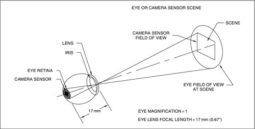
The camera lens is analogous to the lens of the human eye (Figure 21.6) and collects the reflected radiation from the scene much like the lens of your eye or a film camera. The function of the lens is to collect reflected light from the scene and focus it into an image onto the CCTV camera sensor. A fraction of the light reaching the scene from the natural or artificial illumination source is reflected toward the camera and intercepted and collected by the camera lens. As a general rule, the larger the lens diameter, the more the light will be gathered, the brighter the image on the sensor, and the better the final image on the monitor. This is why larger aperture (diameter) lenses, having a higher optical throughput, are better (and more expensive) than smaller diameter lenses that collect less light. Under good lighting conditions—bright indoor lighting, outdoors under sunlight—the large-aperture lenses are not required and there is sufficient light to form a bright image on the sensor by using small-diameter lenses.
Most video applications use a fixed-focal-length (FFL) lens. The FFL lens, like the human eye lens, covers a constant angular FOV. The FFL lens images a scene with constant fixed magnification. A large variety of CCTV camera lenses are available with different focal lengths (FLs) that provide different FOVs. Wide-angle, medium-angle, and narrow-angle (telephoto) lenses produce different magnifications and FOVs. Zoom and varifocal lenses can be adjusted to have variable FLs and FOVs.
Most CCTV lenses have an iris diaphragm (as does the human eye) to adjust the open area of the lens and change the amount of light passing through it and reaching the sensor. Depending on the application, manual- or automatic-iris lenses are used.
In an automatic-iris CCTV lens, as in a human eye lens, the iris closes automatically when the illumination is too high and opens automatically when it is too low, maintaining the optimum illumination on the sensor at all times. Figure 21.7 shows representative samples of CCTV lenses, including FFL, varifocal, zoom, pinhole, and a large catadioptric lens for long-range outdoor use (which combines both mirror and glass optical elements).

The Camera Function
The lens focuses the scene onto the camera image sensor, which acts like the retina of the eye or the film in a photographic camera. The video camera sensor and electronics convert the visible image into an equivalent electrical signal suitable for transmission to a remote monitor. Figure 21.8 is a block diagram of a typical analog CCTV camera.

The camera converts the optical image produced by the lens into a time-varying electric signal that changes (modulates) in accordance with the light-intensity distribution throughout the scene. Other camera electronic circuits produce synchronizing pulses so that the time-varying video signal can later be displayed on a monitor or recorder or printed out as a hard copy on a video printer. While cameras may differ in size and shape depending on specific type and capability, the scanning process used by most cameras is essentially the same. Almost all cameras must scan the scene, point by point, as a function of time (an exception is the image intensifier). Solid-state CCD or CMOS color and monochrome cameras are used in most applications. In scenes with low illumination, sensitive CCD cameras with IR illuminators are used. In scenes with very low illumination and where no active illumination is permitted (i.e., covert), low-light-level (LLL)-intensified CCD (ICCD) cameras are used. These cameras are complex and expensive.
Figure 21.9 shows a block diagram of an analog camera with (a) DSP and (b) the all-digital Internet protocol (IP) video camera.

In the early 2000s, the nonbroadcast, tube-type color cameras available for security applications lacked long-term stability, sensitivity, and high resolution. Color cameras were not used much in security applications until solid-state color CCTV cameras became available through the development of solid-state color sensor technology and widespread use of consumer color CCD cameras used in camcorders. Color cameras have now become standard in security systems and most CCTV security cameras in use today are color. Figure 21.10 shows representative CCTV cameras including monochrome and color solid-state CCD and CMOS cameras, a small single board camera, and a miniature remote head camera.

The Transmission Function
Once the camera has generated an electrical video signal representing the scene image, the signal is transmitted to a remote security-monitoring site via some transmission means: coaxial cable, two-wire twisted-pair, LAN, WAN, intranet, Internet, fiber optics, or wireless techniques. The choice of transmission medium depends on factors such as distance, environment, and facility layout.
If the distance between the camera and the monitor is short (10-500 feet), coaxial cable, UTP, and fiber optics or wireless is used. For longer distances (500 feet to several thousand feet) or where there are electrical disturbances, fiber optic cable and UTP are preferred. For very long distances and in harsh environments (frequent lightning storms) or between separated buildings where no electrical grounding between buildings is in place, fiber optics is the choice. In applications where the camera and monitor are separated by roadways or where there is no right of way, wireless systems using RF, microwave, or optical transmission are used. For transmission over many miles or from city to city, the only choice is the digital or Internet IP camera that uses compression techniques and transmits over the Internet. Images from these Internet systems are not real time but sometimes come close to real time.
The Monitor Function
At the monitoring site, CRT or LCD, HD, or plasma monitor converts the video signal back into a visual image on the monitor face via electronic circuitry similar but inverse to that in the camera.
The final scene is produced by a scanning electron beam in the CRT in the video monitor. This beam activates the phosphor on the CRT, producing a representation of the original image onto the faceplate of the monitor. Alternatively, the video image is displayed point by point on an LCD or plasma screen. A permanent record of the monitor video image is made using a VCR tape or DVR hard disk magnetic recorder and a permanent hard copy is printed with a video printer.
The Recording Function
For decades, the VCR has been used to record monochrome and color video images. The real-time and TL VCR magnetic tape systems have been a reliable and efficient means for recording security scenes.
Beginning in the mid-1990s, the DVR was developed using a computer hard disk drive and digital electronics to provide video image recording. The availability of large memory disks (hundreds of megabytes) made these machines available for long-duration security recording. Significant advantages of the DVR over the VCR are the high reliability of the disk as compared with the cassette tape, its ability to perform high-speed searches (retrieval of images) anywhere on the disk, and absence of image deterioration after many copies are made.
Scene Illumination
A scene is illuminated by either natural or artificial illumination. Monochrome cameras can operate with any type of light source. Color cameras need light that contains all the colors in the visible spectrum and light with a reasonable balance of all the colors to produce a satisfactory color image.
Natural Light
During daytime, the amount of illumination and spectral distribution of light (color) reaching a scene depends on the time of day and atmospheric conditions. The color spectrum of the light reaching the scene is important if color CCTV is used. Direct sunlight produces the highest contrast scene, allowing maximum identification of objects. On a cloudy or overcast day, less light is received by the objects in the scene resulting in less contrast. To produce an optimum camera picture under the wide variation in light levels (daytime to nighttime), an automatic-iris camera system is required. Table 21.1 shows the light levels for outdoor illumination under bright sun, partial clouds, and overcast day down to overcast night.
Table 21.1
Light Levels Under Daytime and Nighttime Conditions
| Condition | Illumination | Comments | |
| fc | lux | ||
| Direct sunlight | 10,000 | 107,500 | Daylight range |
| Full daylight | 1000 | 10,750 | |
| Overcast day | 100 | 1075 | |
| Very dark day | 10 | 107.5 | |
| Twilight | 1 | 10.75 | |
| Deep twilight | 0.1 | 1.075 | |
| Full moon | 0.01 | 0.1075 | LLL range |
| Quarter moon | 0.001 | 0.01075 | |
| Starlight | 0.0001 | 0.001075 | |
| Overcast night | 0.00001 | 0.0001075 | |

Note: 10.75 lux = 1 fc.
Scene illumination is measured in foot-candles (fc) and can vary from 10,000 to 1 (or more). This exceeds the dynamic operating range of most camera sensors for producing a good-quality video image. After the sun has gone below the horizon and if the moon is overhead, reflected sunlight from the moon illuminates the scene and may be detected by a sensitive monochrome camera. Detection of information in a scene under this condition requires a very sensitive camera, since there is very little light reflected into the camera lens from the scene. As an extreme, when the moon is not overhead or is obscured by cloud cover, the only light received is ambient light from (1) local man-made lighting sources; (2) nightglow caused by distant ground lighting reflecting off particulate (pollution), clouds, and aerosols in the lower atmosphere; and (3) direct light caused by starlight. This is the most severe lighting condition and requires (1) ICCD, (2) monochrome camera with IR light-emitting diode (LED) illumination, or (3) thermal IR camera. Table 21.2 summarizes the light levels occurring under daylight and these LLL conditions and the operating ranges of typical cameras. The equivalent metric measure of light level (lux) compared with the fc is given. One fc is equivalent to approximately 9.3 lux.
Table 21.2
Camera Capability Under Natural Lighting Conditions and Camera Requirement per Lighting Conditions
| Illumination Condition | Illumination | ||||||
| fc | lux | Vidicona | CCD | CMOS | ICCD | ISITa | |
| Overcast night | 0.00001 | 0.0001075 | |||||
| Starlight | 0.0001 | 0.001075 | |||||
| Quarter moon | 0.001 | 0.01075 | |||||
| Full moon | 0.01 | 0.1075 | |||||
| Deep twilight | 0.1 | 1.075 | |||||
| Twilight | 1 | 10.075 | |||||
| Very dark day | 10 | 107.5 | Operating range of typical cameras | ||||
| Overcast day | 100 | 1075 | |||||
| Full daylight | 1000 | 10,750 | |||||
| Direct sunlight | 10,000 | 107,500 | |||||

ISIT, intensified silicon intensified target.
a For reference only.
Artificial Light
Artificial illumination is often used to augment outdoor lighting to obtain adequate video surveillance at night. The light sources used are tungsten, tungsten-halogen, metal-arc, mercury, sodium, xenon, IR lamps, and LED IR arrays. Figure 21.11 illustrates several examples of these lamps.
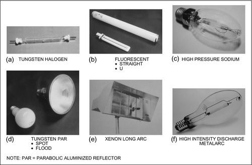
The type of lighting chosen depends on architectural requirements and the specific application. Often a particular lighting design is used for safety reasons so that personnel at the scene can see better and for improving the video picture. Tungsten and tungsten-halogen lamps have by far the most balanced color and are best for color cameras. The most efficient visual outdoor light types are the low- and high-pressure sodium-vapor lamps to which the human eye is most sensitive. These lamps, however, do not produce all colors (missing blue and green) and therefore are not good light sources for color cameras. Metal-arc lamps have excellent color rendition. Mercury-arc lamps provide good security illumination but do not produce the color red; therefore, they are not as good as the metal-arc lamps at producing excellent-quality color video images. Long-arc xenon lamps with excellent color rendition are often used in outdoor sports arenas and large parking areas.
LED IR illumination arrays mounted in monochrome video cameras or located near the camera are used to illuminate scenes when there is insufficient lighting. Since they only emit energy in the IR spectrum, they can only be used with monochrome cameras. They are used at short ranges (10-25 feet) with wide-angle lenses (50-75° FOV) or at medium long ranges (25-200 feet) with medium to narrow FOV lenses (5-20°).
Artificial indoor illumination is similar to outdoor illumination, with fluorescent lighting used extensively in addition to the high-pressure sodium, metal-arc, and mercury lamps. Since indoor lighting has a relatively constant light level, automatic-iris lenses are often unnecessary. However, if the CCTV camera views a scene near an outside window or a door where additional light comes in during the day, or if the indoor lighting changes between daytime and nighttime operation, then an automatic-iris lens or electronically shuttered camera is required. The illumination level from most indoor lighting is significantly lower by 100-1000 times than that of sunlight.
Scene Characteristics
The quality of the video image depends on various scene characteristics that include: (1) the scene lighting level, (2) the sharpness and contrast of objects relative to the scene background, (3) whether objects are in a simple, uncluttered background or in a complicated scene, and (4) whether objects are stationary or in motion. These scene factors will determine whether the system will be able to detect, determine orientation, recognize, or identify objects and personnel. As will be seen later, the scene illumination—via sunlight, moonlight, or artificial sources—and the actual scene contrast play important roles in the type of lens and camera necessary to produce a quality image on the monitor.
Target Size
In addition to the scene’s illumination level and the object’s contrast with respect to the scene background, the object’s apparent size, that is, its angular FOV as seen by the camera, influences a person’s ability to detect it. (Try to find a football referee with a striped shirt in a field of zebras.)
The requirements of a video system are a function of the application. These include: (1) detection of the object or movement in the scene; (2) determination of the object’s orientation; (3) recognition of the type of object in the scene, that is, adult or child, car or truck; or (4) identification of the object (Who is the person? Exactly what kind of truck is it?). Making these distinctions depends on the system’s resolution, contrast, and signal-to-noise ratio (S/N). In a typical scene, the average observer can detect a target about one-tenth of a degree in angle. This can be related to a standard video picture that has 525 horizontal lines (from the National Television System Committee; NTSC) and about 350 TV line vertical and 500 TV line horizontal resolution. Figure 21.12 and Table 21.3 summarize the number of lines required to detect, orient, recognize, or identify an object in a television picture. The number of TV lines required will increase for conditions of poor lighting, highly complex backgrounds, reduced contrast, or fast movement of the camera or target.

Reflectivity
The reflectivity of different materials varies greatly depending on its composition and surface texture. Table 21.4 gives some examples of materials and objects viewed by video cameras and their respective reflectivity.
Table 21.4
Reflectivity of Common Materials
| Material | Reflectivitya (%) |
| Snow | 85-95 |
| Asphalt | 5 |
| Plaster (white) | 90 |
| Sand | 40-60 |
| Trees | 20 |
| Grass | 40 |
| Clothes | 15-30 |
| Concrete-new | 40 |
| Concrete-old | 25 |
| Clear windows | 70 |
| Human face | 15-25 |
| Wood | 10-20 |
| Painted wall (white) | 75-90 |
| Red brick | 25-35 |
| Parking lot and automobiles | 40 |
| Aluminum building (diffuse) | 65-70 |
a Visible spectrum: 400-700 nm.
Since the camera responds to the amount of light reflected from the scene, it is important to recognize that objects have a large range of reflectivity. The objects with the highest reflectivity produce the brightest images. To detect one object located within the area of another the objects must differ in reflectivity, color, or texture. Therefore, if a red box is in front of a green wall and both have the same reflectivity and texture, the box will not be seen on a monochrome video system. In this case, the total reflectivity in the visible spectrum is the same for the green wall and the red box. This is where the color camera shows its advantage over the monochrome camera.
The case of a color scene is more complex. While the reflectivity of the red box and the green wall may be the same as averaged over the entire visible spectrum from blue to red, the color camera can distinguish between green and red.
It is easier to identify a scene characteristic by a difference in color in a color scene than it is to identify it by a difference in gray scale (intensity) in a monochrome scene. For this reason, the target size required to make an identification in a color scene is generally less than it is to make the same identification in a monochrome scene.
Effects of Motion
A moving object in a video image is easier to detect, but more difficult to recognize than a stationary one provided that the camera can respond to it. LLL cameras produce sharp images for stationary scenes but smeared images for moving targets. This is caused by a phenomenon called “lag” or “smear.” Solid-state sensors (CCD, CMOS, and ICCD) do not exhibit smear or lag at normal light levels; therefore, they can produce sharp images of both stationary and moving scenes. Some image intensifiers exhibit smear when the scene moves fast or when there is a bright light in the FOV of the lens.
When the target in the scene moves very fast, the inherent camera scan rate (30 frames per second; fps) causes a blurred image of this moving target in the camera. This is analogous to the blurred image in a still photograph when the shutter speed is too slow for the action. There is no cure for this as long as the standard NTSC television scan rate (30 fps) is used. However, CCTV snapshots can be taken without any blurring using fast-shuttered CCD cameras. For special applications in which fast-moving targets must be imaged and tracked, higher scan rate cameras are available.
Scene Temperature
Scene temperature has no effect on the video image in a CCD, CMOS, or ICCD sensor. These sensors do not respond to temperature changes or temperature differences in the scene. On the other hand, IR thermal imaging cameras do respond to temperature differences and changes in temperature in the scene. Thermal imagers do not respond to visible light or the very near-IR radiation like that produced by IR LEDs. The sensitivity of IR thermal imagers is defined as the smallest change in temperature in the scene that can be detected by the thermal camera.
Lenses
A lens collects reflected light from the scene and focuses it onto the camera image sensor.
This is analogous to the lens of the human eye focusing a scene onto the retina at the back of the eye (Figure 21.6). As in the human eye, the camera lens inverts the scene image on the image sensor, but the eye and the camera electronics compensate (invert the image) to perceive an upright scene. The retina of the human eye differs from any CCTV lens in that it focuses a sharp image only in the central 10% of its total 160° FOV. All vision outside the central focused scene is out of focus. This central imaging part of the human eye can be characterized as a medium FL lens that is of 16-25 mm. In principle, Figure 21.6 represents the function of any lens in a video system.
Many different lens types are used for video surveillance and safety applications. They range from the simplest FFL manual-iris lenses to the more complex varifocal and zoom lenses, with an automatic iris being an option for all types.
In addition, pinhole lenses are available for covert applications, split-image lenses for viewing multiple scenes on one camera, right-angle lenses for viewing a scene perpendicular to the camera axis, and rigid or flexible fiber optic lenses for viewing through thick walls, under doors, and so forth.
FFL Lens
Figure 21.13 illustrates three fixed FFL or fixed FOV lenses with narrow (telephoto), medium, and wide FOVs and the corresponding FOV obtained when used with a 1/3-inch camera sensor format.

Wide FOV (short FL) lenses permit viewing a very large scene (wide angle) with low magnification and therefore provide low resolution and low identification capabilities. Narrow FOV or telephoto lenses have high magnification with high resolution and high identification capabilities.
Zoom Lens
The zoom lens is more versatile and complex than the FFL lens. Its FL is variable from wide-angle to narrow-angle (telephoto) FOV (Figure 21.14).

The overall camera/lens FOV depends on the lens FL and the camera sensor size as shown in Figure 21.14. Zoom lenses consist of multiple lens groups that are moved within the lens barrel by means of an external zooming ring (manual or motorized), changing the lens FL and angular FOV without having to switch lenses or refocusing. Zoom FL ratios can range from 6:1 up to 50:1. Zoom lenses are usually large and used on pan/tilt mounts viewing over large areas and distances (25-500 feet).
Varifocal Lens
The varifocal lens is a variable FL lens used in applications where an FFL lens would be used. In general, they are smaller and cost much less than zoom lenses. Like the zoom lens, the varifocal lens is used because its FL (angular FOV) can be changed manually or automatically, using a motor, by rotating the barrel on the lens. This feature makes it convenient to adjust the FOV to a precise angle when installed on the camera. Typical varifocal lenses have FLs of 3-8, 5-12, and 8-50 mm. With just these three lenses, FLs from 3 to 50 mm (91-5° horizontal FOV) can be covered on a 1/3-inch format sensor. Unlike zoom lenses, varifocal lenses must be refocused each time the FL and the FOV are changed. They are not suitable for zoom or pan/tilt applications.
Panoramic—360° Lens
There has always been a need to see “all around,” i.e., an entire room or other location, seeing 360° with one panoramic camera and lens. In the past, 360° FOV camera viewing systems have only been achieved by using multiple cameras and lenses and combining the scenes on a split-screen monitor.
Panoramic lenses have been available for many years but have only recently been combined with digital electronics and sophisticated mathematical transformations to take advantage of their capabilities. Figure 21.15 shows two lenses having a 360° horizontal FOV and a 90° vertical FOV.
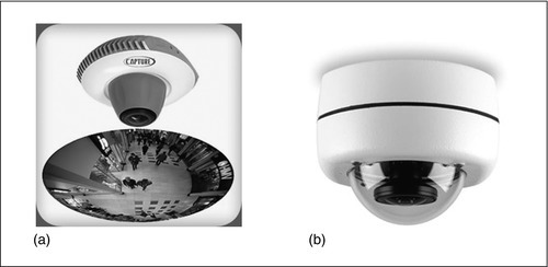
The panoramic lens collects light from the 360° panoramic scene and focuses it onto the camera sensor as a donut-shaped image. The electronics and mathematical algorithm convert this donut-shaped panoramic image into the rectangular (horizontal and vertical) format for normal monitor viewing.
Covert Pinhole Lens
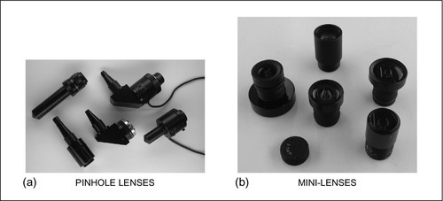
This special security lens is used when the lens and CCTV camera must be hidden. The front lens element or aperture is small (from 1/16 to 5/16 of an inch in diameter). Although this is not the size of a pinhead, it nevertheless has been labeled as such. Figure 21.16 shows examples of straight and right-angle pinhole lenses used with C or CS mount cameras. The very small mini-pinhole lenses are used on the low-cost, small board cameras.
Special Lenses
Some special lenses useful in security applications include split-image, right-angle, relay, and fiber optic lenses (Figure 21.17).

The dual-split and tri-split lenses use only one camera to produce multiple scenes. These are useful for viewing the same scene with different magnifications or different scenes with the same or different magnifications. Using only one camera can reduce cost and increase reliability. These lenses are useful when two or three views are required and only one camera was installed.
The right-angle lens permits a camera using a wide-angle lens installed to view a scene that is perpendicular to the camera’s optical axis. There are no restrictions on the FLs, so they can be used in wide- or narrow-angle applications.
The flexible and rigid coherent fiber optic lenses are used to mount a camera several inches to several feet away from the front lens as might be required to view from the opposite side of a wall or in a hazardous environment. The function of the fiber optic bundle is to transfer the focused visual image from one location to another. This may be useful for (1) protecting the camera and (2) locating the lens in one environment (outdoors) and the camera in another (indoors).
Cameras
The camera lens focuses the visual scene image onto the camera sensor area point by point, and the camera electronics transforms the visible image into an electrical signal. The camera video signal (containing all picture information) is made up of frequencies from 30 cycles per second, or 30 Hz, to 4.2 million cycles per second, or 4.2 MHz. The video signal is transmitted via a cable (or wireless) to the monitor display.
Almost all security cameras in use today are color or monochrome CCD with the rapid emergence of CMOS types. These cameras are available as low-cost single printed circuit board cameras with small lenses already built in, with or without a housing used for covert and overt surveillance applications. More expensive cameras in a housing are larger and more rugged and have a C or CS mechanical mount for accepting any type of lens. These cameras have higher resolution and light sensitivity and other electrical input/output features suitable for multiple camera CCTV systems. The CCD and CMOS cameras with LED IR illumination arrays can extend the use of these cameras to nighttime use. For LLL applications, the ICCD and IR cameras provide the highest sensitivity and detection capability.
Significant advancements in camera technology have been made in the last few years particularly in the use of DSP in the camera and development of the IP camera. All security cameras manufactured between the 1950s and 1980s were the vacuum tube type, either vidicon, silicon, or LLL types using silicon-intensified target (SIT) and intensified ISIT. In the 1980s, the CCD and CMOS solid-state video image sensors were developed and remain the mainstay in the security industry. Increased consumer demand for video recorders using CCD sensors in camcorders and the CMOS sensor in digital still-frame cameras caused a technology explosion and made these small, high-resolution, high-sensitivity, monochrome, and color solid-state cameras available for security systems.
The security industry now has both analog and digital surveillance cameras at its disposal. Up until the mid-1990s, analog cameras dominated, with only rare use of DSP electronics, and the digital Internet camera was only being introduced to the security market. Advances in solid-state circuitry, the demand from the consumer market, and the availability of the Internet were responsible for the rapid use of digital cameras for security applications.
The Scanning Process
Two methods used in the camera and monitor video scanning process are raster scanning and progressive scanning. In the past, analog video systems have all used the raster scanning technique; however, newer digital systems are now using progressive scanning. All cameras use some form of scanning to generate the video picture. A block diagram of the CCTV camera and a brief description of the analog raster scanning process and video signal are shown in Figures 21.8, 21.9, 21.18, and 21.19.


The camera sensor converts the optical image from the lens into an electrical signal. The camera electronics process the video signal and generate a composite video signal containing the picture information (luminance and color) and horizontal and vertical synchronizing pulses.
Signals are transmitted in what is called a frame of picture video, made up of two fields of information. Each field is transmitted in 1/60 of a second and the entire frame in 1/30 of a second, for a repetition rate of 30 fps. In the United States, this format is the Electronic Industries Association (EIA) standard called the NTSC system. The European standard uses 625 horizontal lines with a field taking 1/50 of a second and a frame 1/25 of a second and a repetition rate of 25 fps.
Raster Scanning
In the NTSC system, the first picture field is created by scanning 262½ horizontal lines. The second field of the frame contains the second 262½ lines, which are synchronized so that they fall between the gaps of the first field lines thus producing one completely interlaced picture frame containing 525 lines. The scan lines of the second field fall exactly halfway between the lines of the first field resulting in a 2-to-1 interlace system. As shown in Figure 21.18, the first field starts at the upper left corner (of the camera sensor or the CRT monitor) and progresses down the sensor (or screen), line by line, until it ends at the bottom center of the scan.
Likewise, the second field starts at the top center of the screen and ends at the lower-right corner. Each time one line in the field traverses from the left side of the scan to the right it corresponds to one horizontal line as shown in the video waveform at the bottom of Figure 21.18. The video waveform consists of negative synchronization pulses and positive picture information. The horizontal and vertical synchronization pulses are used by the video monitor (and VCR, DVR, or video printer) to synchronize the video picture and paint an exact replica in time and intensity of the camera scanning function onto the monitor face. Black picture information is indicated on the waveform at the bottom (approximately 0 V) and the white picture information at the top (1 V). The amplitude of a standard NTSC signal is 1.4 V peak to peak. In the 525-line system, the picture information consists of approximately 512 lines. The lines with no picture information are necessary for vertical blanking, which is the time when the camera electronics or the beam in the monitor CRT moves from the bottom to the top to start a new field.
Random-interlace cameras do not provide complete synchronization between the first and the second fields. The horizontal and the vertical scan frequencies are not locked together; therefore, fields do not interlace exactly. This condition, however, results in an acceptable picture, and the asynchronous condition is difficult to detect. The 2-to-1 interlace system has an advantage when multiple cameras are used with multiple monitors and/or recorders in that they prevent jump or jitter when switching from one camera to the next.
The scanning process for solid-state cameras is different. The solid-state sensor consists of an array of very small picture elements (pixels) that are read out serially (sequentially) by the camera electronics to produce the same NTSC format—525 TV lines in 1/30 of a second (30 fps)—as shown in Figure 21.19.
The use of digital cameras and digital monitors has changed the way the camera and monitor signals are processed, transmitted, and displayed. The final presentation on the monitor looks similar to the analog method, but instead of seeing 525 horizontal lines (NTSC system), individual pixels are seen in a row and column format. In the digital system, the camera scene is divided into rows and columns of individual pixels (small points in the scene) each representing the light intensity and color for each point in the scene. The digitized scene signal is transmitted to the digital display be it LCD, plasma, or other, and reproduced on the monitor screen pixel by pixel providing a faithful representation of the original scene.
Digital and Progressive Scan
The digital scanning is accomplished in the 2-to-1 interlace mode as in the analog system, or in a progressive mode. In the progressive mode, each line is scanned in a linear sequence: line 1, then line 2, line 3, and so forth. Solid-state camera sensors and monitor displays can be manufactured with a variety of horizontal and vertical pixels formats. The standard aspect ratio is 4:3 as in the analog system and 16:9 for the wide screen. Likewise, there are many different combinations of pixel numbers available in the sensor and display. Some standard formats for color CCD cameras are 512 h × 492 v for 330 TV line resolution and 768 h × 494 v for 480 TV line resolution, and for color LCD monitors it is 1280 h × 1024 v.
Solid-State Cameras
Video security cameras have gone through rapid technological changes during the last half of the 1980s to the present. For decades, the vidicon tube camera was the only security camera available. In the 1980s, the more sensitive and rugged silicon-diode tube camera was the best available. In the late 1980s, the invention and development of the digital CCD and later the CMOS cameras replaced the tube camera. This technology coincided with rapid advancement in DSP in cameras, the IP camera, and use of digital transmission of the video signal over LAN, WANs, and the Internet.
The two generic solid-state cameras that account for most security applications are the CCD and the CMOS.
The first generation of solid-state cameras available from most manufacturers had 2/3-inch (sensor diagonal) and 1/2-inch sensor formats. As the technology improved, smaller formats evolved. Most solid-state cameras in use today are available in three image sensor formats: 1/2, 1/3, and 1/4 inch. The 1/2-inch format produces higher resolution and sensitivity at a higher cost. The 1/2-inch and smaller formats permitted the use of smaller, less expensive lenses as compared with the larger formats. Many manufacturers now produce 1/3-inch and 1/4-inch format cameras with excellent resolution and light sensitivity. Solid-state sensor cameras are superior to their predecessors because of their (1) precise, repeatable pixel geometry, (2) low power requirements, (3) small size, (4) excellent color rendition and stability, and (5) ruggedness and long life expectancy. At present, solid-state cameras have settled into three main categories: (1) analog, (2) digital, and (3) Internet.
Analog
Analog cameras have been with the industry since CCTV has been used in security. Their electronics are straightforward and the technology is still used in many applications.
Digital
Since the second half of the 1990s, there has been an increase in the use of DSP in cameras. It significantly improves the performance of the camera by (1) automatically adjusting to large light level changes (eliminating the automatic iris), (2) integrating the VMD into the camera, and (3) automatically switching the camera from color operation to higher sensitivity monochrome operation, as well as other features and enhancements.
Internet
The most recent camera technology advancement is manifest in the IP camera. This camera is configured with electronics that connects to the Internet and the WWW network through an Internet service provider. Each camera is provided with a registered Internet address and can transmit the video image anywhere on the network. This is really remote video monitoring at its best. The camera site is viewed from anywhere by entering the camera Internet address (ID number) and proper password. Password security is used so that only authorized users can enter the Web site and view the camera image. Two-way communication is used so that the user can control camera parameters and direct the camera operation (pan, tilt, zoom, etc.) from the monitoring site.
LLL-Intensified Camera
When a security application requires viewing during nighttime conditions where the available light is moonlight, starlight, or other residual reflected light and the surveillance must be covert (no active illumination like IR LEDs), LLL-ICCD cameras are used. The ICCD cameras have sensitivities between 100 and 1000 times higher than the best solid-state cameras. The increased sensitivity is obtained by the use of a light amplifier mounted in between the lens and the CCD sensor. LLL cameras cost between 10 and 20 times more than CCD cameras.
Thermal Imaging Camera
An alternative to the ICCD camera is the thermal IR camera. Visual cameras see only visible light energy from the blue end of the visible spectrum to the red end (approximately 400-700 nm). Some monochrome cameras see beyond the visible region into the near-IR region of the spectrum up to 1000 nm. This IR energy, however, is not thermal IR energy. Thermal IR cameras using thermal sensors respond to thermal energy in the 3-5 and 8-14 μm range. The IR sensors respond to the changes in heat (thermal) energy emitted by the targets in the scene. Thermal imaging cameras can operate in complete darkness, as they require no visible or IR illumination whatsoever. They are truly passive nighttime monochrome imaging sensors. They can detect humans and any other warm objects (animals, vehicle engines, ships, aircraft, warm/hot spots in buildings) or other objects against a scene background.
Panoramic—360° Camera
Powerful mathematical techniques combined with the unique 360° panoramic lens have made a 360° panoramic camera possible. In operation, the lens collects and focuses the 360° horizontal by up to 90° vertical scene (one-half of a sphere; a hemisphere) onto the camera sensor. The image takes the form of a “donut” on the sensor (Figure 21.20).
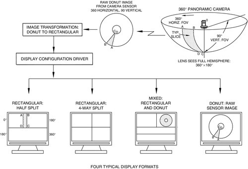
The camera/lens is located at the origin (0). The scene is represented by the surface of the hemisphere. As shown, a small part (slice) of the scene area (A, B, C, D) is “mapped” onto the sensor as a, b, c, d. In this way, the full scene is mapped onto the sensor. Direct presentation of the donut-ring video image onto the monitor does not result in a useful picture.
That is where the use of a powerful mathematical algorithm comes in. Digital processing in the computer using the algorithm transforms the donut-shaped image into the normal format seen on a monitor, that is, horizontal and vertical.
All of the 0-360° horizontal by 90° vertical images cannot be presented on a monitor in a useful way—there is just too much picture “squeezed” into the small screen area. This condition is solved by computer software by looking at only a section of the entire scene at any particular time.
The main attributes of the panoramic system include: (1) capturing a full 360° FOV, (2) the ability to digitally pan/tilt to anywhere in the scene and digitally zoom any scene area, (3) having no moving parts (no motors, etc., that can wear out), and (4) having multiple operators that can view any part of the scene in real time or at a later time.
The panoramic camera requires a high-resolution camera since so much scene information is contained in the image. Camera technology has progressed so that these digital cameras are available and can present a good image of a zoomed-in portion of the panoramic scene.
Transmission
By definition, the camera must be remotely located from the monitor and therefore the video signal must be transmitted by some means from one location to another. In security applications, the distance between the camera and the monitor may be from tens of feet to many miles or, perhaps, completely around the globe. The transmission path may be inside buildings, outside buildings, above ground, underground, through the atmosphere, or in almost any environment imaginable. For this reason, the transmission means must be carefully assessed and an optimum choice of hardware made to satisfactorily transmit the video signal from the camera to the monitoring site. There are many ways to transmit the video signal from the camera to the monitoring site. Figure 21.21 shows some examples of transmission cables.

The signal can be analog or digital. It can be transmitted via electrical conductors using coaxial cable or UTP, by fiber optics, by LAN or WAN, and intranet or Internet.
Particular attention should be paid to transmission means when transmitting color video signals, since the color signal is significantly more complex and susceptible to distortion than monochrome. There are advantages and disadvantages of all of the transmission means and the hardware available to transmit the video signal.
Hard-wired
There are several hard-wired means for transmitting a video signal: coaxial cable, UTP, LAN, WAN, intranet, Internet, and fiber optic cable.
Fiber optic cable is used for long distances and when there is interfering electrical noise. LANs and Internet connections are digital transmission techniques used in larger security systems and where the signal must be transmitted over existing computer networks or over long distances.
Coaxial cable
The most common video signal transmission method is the coaxial cable. This cable has been used since the inception of CCTV and is still in use today. The cable is inexpensive, easy to terminate at the camera and monitor ends, and transmits a faithful video signal with little or no distortion or loss. It has a 75-ohm electrical impedance, which matches the impedance of the camera and monitor, ensuring a distortion-free video image. This coaxial cable has a copper electrical shield and center conductor that works well over distances up to 1000 feet.
UTP
In the 1990s, UTP video transmission came into vogue. The technique uses a transmitter at the camera and a receiver at the monitor with two twisted copper wires connecting them. Several reasons for its increased popularity are that (1) it can be used over longer distances than coaxial cable, (2) it uses inexpensive wire, (3) many locations already have two-wire twisted-pair installed, (4) it uses a low-cost transmitter and receiver, and (5) it has higher electrical noise immunity as compared to coaxial cable. The UTP using a sophisticated electronic transmitter and receiver can transmit the video signal to 2000-3000 feet.
LAN, WAN, intranet, and internet
The evolution of the LAN, WAN, intranet, and Internet revolutionized the transmission of video signals in a new form (digital) which significantly expanded the scope and effectiveness of video for security systems. The widespread use of business computers and consequent use of these networks provided an existing digital network protocol and communications suitable for video transmission. The Internet attained widespread use in the late 1990s and truly revolutionized digital video transmission. This global computer network provided the digital backbone path to transmit digital video, audio, and command signals from anywhere on the globe.
The video signal transmission techniques described so far provide a means for real-time transmission of a video signal, requiring a full 4.2-MHz bandwidth to reproduce real-time motion. When these techniques cannot be used for real-time video, alternative digital techniques are used. In these systems, a non-real-time video transmission takes place, so that some scene action is lost. Depending on the action in the scene, the resolution, from near real time (15 fps) to slow scan (a few fps) of the video image is transmitted. The digitized and compressed video signal is transmitted over a LAN or Internet network and decompressed and reconstructed at the receiver/monitoring site.
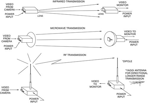
Wireless
In legacy analog video surveillance systems, it is often more economical or beneficial to transmit the real-time video signal without cable (wireless) from the camera to the monitor using an RF or IR atmospheric link. In digital video systems using digital transmission, the use of wireless networks (WiFi) permits routing the video and control signals to any remote location. In both the analog and the digital systems, some form of video scrambling or encryption is often used to remove the possibility of eavesdropping by unauthorized personnel outside the system. Three important applications for wireless transmission include: (1) covert and portable rapid deployment video installations, (2) building-to-building transmission over a roadway, and (3) parking lot light poles to building. The Federal Communications Commission (FCC) restricts some wireless transmitting devices using microwave frequencies or RF to government and law enforcement use but has given approval for many RF and microwave transmitters for general security use. These FCC-approved devices operate above the normal television frequency bands at approximately 920 MHz and 2.4 and 5.8 GHz. The atmospheric IR link is used when a high-security link is required. This link does not require an FCC approval and transmits a video image over a narrow beam of visible light or near-IR energy. The beam is very difficult to intercept (tap). Figure 21.22 illustrates some of the Wireless Transmission Techniques Available Today.
Fiber optics
Fiber optic transmission technology has advanced significantly in the last 5-10 years and represents a highly reliable, secure means of transmission. Fiber optic transmission holds several significant advantages over other hard-wired systems: (1) very long transmission paths up to many miles without any significant degradation in the video signal with monochrome or color; (2) immunity to external electrical disturbances from weather or electrical equipment; (3) very wide bandwidth, permitting one or more video, control, and audio signals to be multiplexed on a single fiber; and (4) resistance to tapping (eavesdropping) and therefore a very secure transmission means.
While the installation and termination of fiber optic cable requires a more skilled technician, it is well within the capability of qualified security installers. Many hard-wired installations requiring the optimum color and resolution rendition use fiber optic cable.
Switchers
The video switcher accepts video signals from many different video cameras and connects them to one or more monitors or recorders. Using manual or automatic activation or an alarming signal input, the switcher selects one or more of the cameras and directs its video signal to a specified monitor, recorder, or some other device or location.
Standard
There are four basic switcher types: manual, sequential, homing, and alarming. Figure 21.23 shows how these are connected into the video security system.
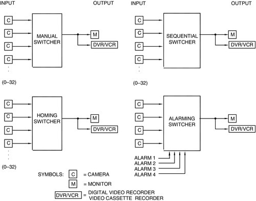
The manual switcher connects one camera at a time to the monitor, recorder, or printer. The sequential switcher automatically switches the cameras in sequence to the output device. The operator can override the automatic sequence with the homing sequential switcher. The alarming switcher connects the alarmed camera to the output device automatically, when an alarm is received.
Microprocessor Controlled
When the security system requires many cameras in various locations with multiple monitors and other alarm input functions, a microprocessor-controlled switcher and keyboard is used to manage these additional requirements (Figure 21.24).

In large security systems, the switcher is microprocessor controlled and can switch hundreds of cameras to dozens of monitors, recorders, or video printers via an RS-232 or other communication control link. Numerous manufacturers make comprehensive keyboard-operated, computer-controlled consoles that integrate the functions of the switcher, pan/tilt pointing, automatic scanning, automatic preset pointing for pan/tilt systems, and many other functions. The power of the software-programmable console resides in its flexibility, expandability, and ability to accommodate a large variety of applications and changes in facility design. In place of a dedicated hardware system built for each specific application, this computer-controlled system can be configured via software for the application.
Quads and Multiplexers
A quad or a multiplexer is used when multiple camera scenes need to be displayed on one video monitor. It is interposed between the cameras and the monitor, accepts multiple camera inputs, memorizes the scenes from each camera, compresses them, and then displays multiple scenes on a single video monitor. Equipment is available to provide 2, 4, 9, 16, and up to 32 separate video scenes on one single monitor. Figure 21.25 shows a block diagram of quad and multiplexer systems.

The most popular presentation is the quad screen showing four pictures. This presentation significantly improves camera-viewing ability in multicamera systems, decreases security guard fatigue, and requires three fewer monitors in a four-camera system. There is a loss of resolution when more than one scene is presented on the monitor with resolution decreasing as the number of scenes increases. One-quarter of the resolution of a full screen is obtained on a quad display (half in horizontal and half in vertical). Quads and multiplexers have front panel controls so that: (1) a full screen image of a camera can be selected, (2) multiple cameras can be displayed (quad, 9, etc.), or (3) the full screen images of all cameras can be sequentially switched with dwell times for each camera, set by the operator.
Monitors
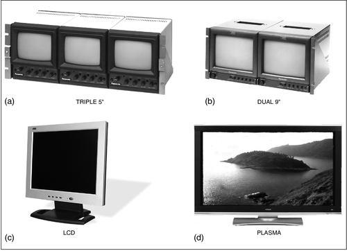
Video monitors can be divided into several categories: (1) monochrome, (2) color, (3) CRT, (4) LCD, (5) plasma, and (6) computer display. Contrary to a popular misconception, larger video monitors do not necessarily have better picture resolution or the ability to increase the amount of intelligence available in the picture. All U.S. NTSC security monitors have 525 horizontal lines; therefore, the vertical resolution is about the same regardless of the CRT monitor size. The horizontal resolution is determined by the system bandwidth. With the NTSC limitation, the best picture quality is obtained by choosing a monitor with resolution equal to or better than the camera or transmission link bandwidth. With the use of a higher-resolution computer monitor and corresponding higher-resolution camera and commensurate bandwidth to match, higher-resolution video images are obtained. Figure 21.26 shows representative examples of video monitors.
Monochrome
Until the late 1990s, the most popular monitor used in CCTV systems was the monochrome CRT monitor. It is still used and is available in sizes ranging from a 1-inch diagonal viewfinder to a large 27-inch diagonal CRT. By far, the most popular monochrome monitor size is the 9-inch diagonal that optimizes video viewing for a person seated about 3 feet away. A second reason for its popularity is that two of these monitors fit into the standard EIA 19-inch wide rack-mount panel. Figure 21.26b shows two 9-inch monitors in a dual rack-mounted version. A triple rack-mount version of a 5-inch diagonal monitor is used when space is at a premium. The triple rack-mounted monitor is popular, since three fit conveniently into the 19-inch EIA rack. The optimum viewing distance for the triple 5-inch diagonal monitor is about 1.5 feet.
Color
Color monitors are now in widespread use and range in size from a 3- to 27-inch diagonal and have required viewing distances and capabilities similar to those of monochrome monitors. Since color monitors require three different colored dots to produce one pixel of information on the monitor, they have lower horizontal resolution than monochrome monitors. Popular color monitor sizes are 13, 15, and 17 inch diagonal.
CRT, LCD, Plasma, HD, Displays
The video security picture is displayed on three basic types of monitor screens: (1) CRT, (2) LCD, and most recently, (3) the plasma display. The analog CRT has seen excellent service from the inception of video and continues as a strong contender providing a low-cost, reliable security monitor. The digital LCD monitor is growing in popularity because of its smaller size (smaller depth)—2-3 inches versus 12-20 inches for the CRT. The LCD is an all solid-state display that accepts the VGA computer signal. Most small (3-10 inch diagonal) and many large (10-17 inch diagonal) LCD monitors also accept an analog video input. The most recent monitor entry into the security market is the digital plasma display. This premium display excels in resolution and brightness and viewing angle and produces the highest quality image in the industry. It is also the most expensive. Screen sizes range from 20 to 42 inches diagonal. Overall depths are small and range in size from 3 to 4 inches. They are available in 4:3 and HDTV 16:9 format.
Audio/Video
Many monitors have built-in audio channel with speakers to produce audio and video simultaneously.
Recorders
The video camera, transmission means, and monitor provide the remote eyes for the security guard, but as soon as the action or event is over, the image disappears from the monitor screen forever. When a permanent record of the live video scene is required, a VCR, DVR, network recorder, or optical disk recorder is used (Figure 21.27).

The video image can be recorded in real time, near real time, or TL. The VCRs record the video signal on a magnetic tape cassette with a maximum real-time recording time of 6 hours and near real time of 24 hours. When extended periods of recording are required (longer than the 6-hour real-time cassette), a TL recorder is used. In the TL process, the video picture is not recorded continuously (real time) but rather “snapshots” are recorded. These snapshots are spread apart in time by a fraction of a second or even seconds so that the total elapsed time for the recording can extend for hundreds of hours. Some present TL systems record over an elapsed time of 1280 hours.
The DVR records the video image on a computer magnetic hard drive (HD) and the optical disk storage on optical disk media. The DVR and optical disk systems have a significant advantage over the VCR with respect to retrieval time of a particular video frame. VCRs take many minutes to fast forward or fast rewind the magnetic tape to locate a particular frame on the tape. Retrieval times on DVRs and optical disks are typically a fraction of a second. The VCR cassette tape is transportable and the DVR and optical disk systems are available with or without removable disks. This means that the video images (digital data) can be transported to remote locations or stored in a vault for safekeeping. The removable DVR and optical disks are about the same size as VHS cassettes.
VCR
Magnetic storage media have been used universally to record the video image. The VCR uses the standard VHS cassette format. The 8-mm Sony format is used in portable surveillance equipment because of its smaller size. Super VHS and Hi-8 formats are used to obtain higher resolution. VCRs can be subdivided into two classes: real time and TL. The TL recorder has significantly different mechanical and electrical features permitting it to take snapshots of a scene at predetermined (user-selectable) intervals. It can also record in real time when activated by an alarm or other input command. Real-time recorders can record up to 6 hours in monochrome or color. TL VCRs are available for recording TL sequences up to 720 hours.
DVR
The DVR has emerged as the new generation of magnetic recorder of choice. A magnetic HD like those used in a microcomputer can store many thousands of images and many hours of video in digital form. The rapid implementation and success of the DVR has resulted from the availability of inexpensive digital magnetic memory storage devices and the advancements made in digital signal compression techniques. Present DVRs are available in single channel and 4 and 16 channels and may be cascaded to provide many more channels.
A significant feature of the DVR is the ability to access (retrieve) a particular frame or recorded time period anywhere on the disk in a fraction of a second. The digital technology also allows many generations (copies) of the stored video images to be made without any errors or degradation of the image.
Optical disk
When very large volumes of video images need to be recorded, an optical disk system is used. Optical disks have a much larger video image database capacity than magnetic disks given the same physical space they occupy. These disks can record hundreds of times longer than their magnetic counterparts.
Hard-Copy Video Printers
A hard-copy printout of a video image is often required as evidence in court, as a tool for apprehending a vandal or thief, or as a duplicate record of some document or person. The printout is produced by a hard-copy video printer, which is a thermal printer that “burns” the video image onto coated paper or an ink-jet or laser printer. The thermal technique used by many hard-copy printer manufacturers produces excellent quality images in monochrome or color. Figure 21.28 shows a monochrome thermal printer and a sample of the hard-copy image quality it produces. In operation, the image displayed on the monitor or played back from the recorder is immediately memorized by the printer and printed out in less than 10 seconds. This is particularly useful if an intrusion or unauthorized act has occurred and been observed by a security guard. An automatic alarm or a security guard can initiate printing the image of the alarm area or of the suspect and the printout can then be given to another guard to take action. For courtroom uses, time, date, and any other information can be annotated on the printed image.

Ancillary Equipment
Most video security systems require additional accessories and equipment, including: (1) camera housings, (2) camera pan/tilt mechanisms and mounts, (3) camera identifiers, (4) VMDs, (5) image splitters/inserters, and (6) image combiners. The two accessories most often used with the basic camera, monitor, and transmission link are camera housings and pan/tilt mounts. Outdoor housings are used to protect the camera and lens from vandalism and the environment. Indoor housings are used primarily to prevent vandalism and for aesthetic reasons. The motorized pan/tilt mechanisms rotate and point the system camera and lens via commands from a remote control console.
Camera Housings
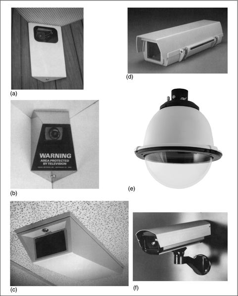
Indoor and outdoor camera housings protect cameras and lenses from dirt, dust, harmful chemicals, the environment, and vandalism. The most common housings are rectangular metal or plastic products, formed from high-impact indoor or outdoor plastic, painted steel, or stainless steel (Figure 21.29). Other shapes and types include cylindrical (tube), corner-mount, ceiling-mount, and dome housings.
Standard rectangular
The rectangular type housing is the most popular. It protects the camera from the environment and provides a window for the lens to view the scene. The housings are available for indoor or outdoor use with a weatherproof and tamper-resistant design. Options include heaters, fans, and window washers.
Dome
A significant part of video surveillance is accomplished using cameras housed in the dome-housing configuration. The dome camera housing can range from a simple fixed monochrome or color camera in a hemispherical dome to a “speed-dome” housing having a high-resolution color camera with remote-controlled pan/tilt/zoom/focus. Other options include presets and image stabilization. The dome-type housing consists of a plastic hemispherical dome on the bottom half. The housing can be clear, tinted, or treated with a partially transmitting optical coating that allows the camera to see in any direction. In a freestanding application (e.g., on a pole, pedestal, or overhang), the top half of the housing consists of a protective cover and a means for attaching the dome to the structure. When the dome housing is mounted in a ceiling, a simpler housing cover is provided and mounted above the ceiling level to support the dome.
Specialty
There are many other specialty housings for mounting in or on elevators, ceilings, walls, tunnels, pedestals, hallways, and so forth. These special types include explosion proof, bullet proof, and extreme environmental construction for arctic and desert use.
Plug and Play
In an effort to reduce installation time for video surveillance cameras, manufacturers have combined the camera, lens, and housing in one assembly ready to be mounted on a ceiling, wall, or pole and plugged into the power source and video transmission cable. These assemblies are available in the form of domes, corner mounts, ceiling mounts, and so forth, making for easy installation in indoor or outdoor applications.
Pan/Tilt Mounts
To extend the angle of coverage of a CCTV lens/camera system a motorized pan/tilt mechanism is often used. Figure 21.30 shows three generic outdoor pan/tilt types: top-mounted, side-mounted, and dome camera.

The pan/tilt motorized mounting platform permits the camera and lens to rotate horizontally (pan) or vertically (tilt) when it receives an electrical command from the central monitoring site. Thus, the camera lens is not limited by its inherent FOV and can view a much larger area of a scene. A camera mounted on a pan/tilt platform is usually provided with a zoom lens. The zoom lens varies the FOV in the pointing direction of the camera/lens from a command from the central security console. The combination of the pan/tilt and zoom lens provides the widest angular coverage for video surveillance. There is one disadvantage with the pan/tilt/zoom configuration compared with the fixed camera installation.
When the camera and lens are pointing in a particular direction via the pan/tilt platform, most of the other scene area the camera is designed to cover is not viewed. This dead area or dead time is unacceptable in many security applications; therefore, careful consideration should be given to the adequacy of their wide FOV pan/tilt design. Pan/tilt platforms range from small, indoor, lightweight units that only pan, up to large, outdoor, environmental designs carrying large cameras, zoom lenses, and large housings. Choosing the correct pan/tilt mechanism is important since it generally requires more service and maintenance than any other part of the video system.
VMD
Another important component in a video surveillance system is a VMD that produces an alarm signal based on a change in the video scene. The VMD can be built into the camera or be a separate component inserted between the camera and the monitor software in a computer. The VMD electronics, analog or digital, store the video frames, compare subsequent frames to the stored frames, and then determine whether the scene has changed. In operation, the VMD digital electronics decides whether the change is significant and whether to call it an alarm to alert the guard or some equipment, or declare it a false alarm.
Screen Splitter
The electronic or optical screen splitter takes a part of several camera scenes (two, three, or more), combines the scenes, and displays them on one monitor. The splitters do not compress the image. In an optical splitter, the image combining is implemented optically at the camera lens and requires no electronics. The electronic splitter/combiner is located between the camera output and the monitor input.
Camera Video Annotation
Camera ID
When multiple cameras are used in a video system, some means must be provided to identify the camera. The system uses a camera identifier component that electronically assigns an alphanumeric code and/or name to each camera displayed on a monitor, recorded on a recorder, or printed on a printer. Alphanumeric and symbol character generators are available to annotate the video signal with the names of cameras, locations in a building, and so forth.
Time and date
When time and date is required on the video image, a time/date generator is used to annotate the video picture. This information is mandatory for any prosecution or courtroom procedure.
Image reversal
Occasionally, video surveillance systems use a single mirror to view the scene. This mirror reverses the video image from the normal left-to-right to a right-to-left (reversed image). The image reversal unit corrects the reversal.
Summary
Video surveillance serves as the remote eyes for management and the security force. It provides security personnel with advance notice of breaches in security, hostile, and terrorist acts, and is a part of the plan to protect personnel and assets. It is a critical subsystem for any comprehensive security plan. In this chapter, an introduction to most of the current video technology and equipment has been described.
Lighting plays an important role in determining whether a satisfactory video picture will be obtained with monochrome and color cameras and LLL ICCD cameras. Thermal IR cameras are insensitive to light and only require temperature differences between the target and the background.
There are many types of lenses available for video systems: FFL, varifocal, zoom, pinhole, panoramic, and so forth. The varifocal and zoom lenses extend the FOV of the FFL lens. The panoramic 360° lens provides entire viewing of the scene. The proper choice of lens is necessary to maximize the intelligence obtained from the scene.
Many types of video cameras are available, such as color, monochrome (with or without IR illumination), LLL intensified, thermal IR, analog and digital, simple and full featured, and daytime and nighttime. There are cameras with built-in VMD to alert security guards and improve their ability to detect and locate personnel and be alerted to activity in the scene.
An important component of the video system is the analog or digital video signal transmission means from the camera to the remote site and to the monitoring and recording site. Hard wire or fiber optics is best if the situation permits. Analog works for short distances and digital for long distances. The Internet works globally.
In multiple camera systems, the quad and multiplexers permit multicamera displays on one monitor. Fewer monitors in the security room can improve guard performance.
The CRT monitor is still a good choice for many video applications. The LCD is the solid-state digital replacement for the CRT. The plasma display provides an all solid-state design that has the highest resolution, brightness, and largest viewing angle, but at the highest cost.
Until about the year 2000, the only practical means for recording a permanent image of the scene was the VCR real-time or TL recorder. Now, new and upgraded systems replace the VCR with the DVR recorder with its increased reliability and fast search and retrieval capabilities to distribute the recorded video over LAN, WAN, intranet, or Internet or wirelessly with WiFi using one of the 802.11 protocols.
Thermal, ink-jet, and laser hard-copy printers produce monochrome and color prints for immediate picture dissemination and permanent records for archiving.
All types of camera/lens housings are available for indoor and outdoor applications. Specialty cameras/housings are available for elevators, stairwells, dome housings for public facilities, casinos, shopping malls, extreme outdoor environments, and so forth.
Pan/tilt assemblies for indoor and outdoor scenarios significantly increase the overall FOV of the camera system. Small, compact speed domes have found widespread use in many indoor and outdoor video surveillance environments.
Plug-and-play surveillance cameras permit quick installation and turn-on and are available in almost every housing configuration and camera type.
The video components summarized above are used in most video security applications including: (1) retail stores, (2) manufacturing plants, (3) shopping malls, (4) offices, (5) airports, (6) seaports, (7) bus and rail terminals, (8) government facilities, and (9) schools and universities.
There is widespread use of small video cameras and accessories for temporary covert applications. The small size and ease of deployment of many video components and the flexibility in transmission means over short and long distances has made rapid deployment equipment for portable personnel protection systems practical and important. It is clear that the direction the video security industry is taking is the integration of the video security function with digital computing technology and the other parts of the security system: access control, intrusion alarms, fire, and two-way communications. Video security is rapidly moving from the legacy analog technology to the digital automatic video surveillance technology.
Keep in mind also that recording should be kept for 30 days unless your standards or guidelines are different.
Appendix Glossary of Terms
Many terms and definitions used in the security industry are unique to CCTV surveillance; others are derived from the electrooptical-optical and information-computer industries. This comprehensive glossary will help the reader better understand the literature, interpret manufacturers’ specifications, and write bid specifications and requests for quotation. These terms encompass the OCTV, physical computer and communications industries, basic physics, electricity, mechanics, and optics.
Access control Used to control overall access, people’s assets to a building complex, schools, and even transportation companies.
Analog signal Representation of data by continuously variable quantities in digital format as opposed to a finite number of discrete quantities. The electrical signal that varies continuously and does not have discrete values.
Analog television The “standard” television broadcast. Analog signals vary continuously representing fluctuations in color and brightness of a visual scent.
Aperture Opening that will pass light, electrons, or other forms of radiation. In an electron gun, the aperture determines the size of, and has an effect on, the shape of the electron beam. In television optics, the aperture is the effective diameter of the lens that controls the amount of light reaching the image sensor.
Automatic-iris control Electrooptic accessory to a lens that measures the video level of the camera and opens and closes the iris diaphragm to compensate for light changes.
Automatic light control Process by which the illumination incident upon the face of a pickup device is automatically adjusted as a function of scent brightness.
Bandwidth Data-carrying capacity of a device or network connection. The number of hertz (cycles per second) expresses the difference between the lower and upper limiting frequencies of a frequency band. Also the width of a band of frequencies.
Cable A number of electrical conductors (wires) bound in a common sheath. These may be video, data, control, or voice cables. They may also take the form of coaxial or fiber optic cables.
Camera format Video cameras have 1/6-, 1/4-, 1/3-, 1/2-, and 2/3-inch sensor image formats. The actual scanned areas used on the sensors are 3.2 h × 2.4 mm vertical for the 1/4 inch, 4.8 h × 3.6 mm v for the 1/3 inch, 6.4 horizontal × 4.8 mm vertical for the 1/2 inch, and 8.8 h × 6.6 mm v for the 2/3 inch.
Camera housing Enclosure designed to protect the video camera from tampering or theft when indoors or outdoors or from undue environmental exposure when placed outdoors.
Camera, television Electronic device containing a solid-state sensor or an electronic image tube and processing electronics. The image formed by a lens ahead of the sensor is clocked out for a solid-state sensor or rapidly scanned by a moving electron beam in a tube camera. The sensor signal output varies with the local brightness of the image on the sensor. These variations are transmitted to a CRT, LCD, or other display device, where the brightness of the scanning spot is controlled. The scanned location (pixel) at the camera and the scanned spot at the display are accurately synchronized.
Camera tube Electron tube that converts an optical image into an electrical current by a scanning process. Also called a pickup tube or television camera tube.
Candle power (cp) Light intensity expressed in candles. One foot-candle (fc) is the amount of light emitted by a standard candle at a 1-foot distance.
Closed-circuit television (CCTV) Closed television system used within a building or used on the exterior of a building or complex to visually monitor a location or activity for security or industrial purposes. CCTV does not broadcast consumer TV signals, but transmits in analog or digital form over a closed circuit via an electrically conducting cable, fiber optic cable, or wireless transmission. CCTV monitor is part of the CCTV system that receives the picture from the CCTV camera and displays it. CCTV’s role in security (psychological) includes:
2. Records as a witness to various events
3. Recognition and detection
4. Connect active usage
5. Capable of watching many areas at same time
6. Records and transmits
7. Camera can pan and tilt, zoom, and be in color
8. ROI makes it worthwhile
Covert surveillance In television security, the use of camouflaged (hidden) lenses and cameras for the purpose of viewing a scene without being seen.
Digital 8 Sony format that uses Hi-8 or 8-mm tapes to store digital video.
Digital signal Video signal that is comprised from bits of binary data, otherwise known as ones and zeros (1, 0). The video signal travels from the point of its inception to the place where it is stored, and then on to the place where it is displayed as an analog or digital presentation.
Fiber optic bundle, coherent Optical component consisting of many thousands of hair-like fibers coherently assembled so that an image is transferred from one end of the bundle to the other. The length of each fiber is much greater than its diameter. The fiber bundle transmits a picture from one end of the bundle to the other, around curves, and into otherwise inaccessible places by a process of total internal reflection. The positions of all fibers at both ends are located in an exact one-to-one relationship with each other.
Fiber optic transmission Process in which light is transmitted through a long, transparent, flexible fiber, such as glass or plastic, by a series of internal reflections. For video, audio, or data transmission over long distances (thousands of feet, many miles), the light is modulated and transmitted over a single fiber in a protective insulating jacket. For light image transmission, closely packed bundles of fibers can transmit an entire coherent image where each single fiber transmits one component of the whole image.
Fiberscope Bundle of systematically arranged fibers that transmits a monochrome or full-color image that remains undisturbed when the bundle is bent. By mounting an objective lens on one end of the bundle and a relay or magnifying lens on the other, the system images remote objects onto a sensor.
Foot-candle (fc) Unit of illuminance on a surface 1 square foot in area on which there is incident light of 1 lumen. The illuminance of a surface placed 1 foot from a light source that has a luminous intensity of 1 candle.
Foot-lambert A measure of reflected light in a 1-foot area. A unit of luminance equal to 1 candela per square foot or to the uniform luminance at a perfectly diffusing surface emitting or reflecting light at the rate of 1 lumen per square foot.
H.264 Powerful MPEG compression algorithm standard developed through the combined effort of the ITU and MPEG organizations providing excellent compression efficiency and motion detection attributes.
Internet Protocol (IP) Method by which data are sent from one computer to another over the Internet. Each computer, known as a host on the Internet, has one address that uniquely identifies it from all other computers on the Internet. A Web page or an e-mail is sent or received by dividing it into blocks called packets. Each packet contains both the sender’s Internet address and the receiver’s address. Each of these packets can arrive in an order different from the order from which they were sent in. The IP just delivers them and the Transmission Control Protocol (TCP) puts them in the correct order. The most widely used version of the IP is IP Version 4 (IPv4).
IP address On the Internet, each computer and connected appliance (camera switcher, router, etc.) must have a unique address. This series of numbers functions similarly to a street address, identifying the location of both sender and recipient for information dispatched over the computer network. The IP address has 32 bits in an 8-bit quad format. The four groups in decimal format are separated by a period (.). The quad groups represent the network and the machine or host address. An example of an IP address is 124.55.19.64.
Iris Adjustable optical-mechanical aperture built into a camera lens to permit control of the amount of light passing through the lens.
Iris diaphragm Mechanical device within a lens used to control the size of the aperture through which light passes. A device for opening and closing the lens aperture to adjust the f-stop of a lens.
ISO Worldwide federation of national standards bodies from over 130 countries to promote the worldwide standardization of goods and services. The ISO has international agreements that are published as international standards. The scope of ISO covers all technical fields except electrical and electronic engineering, which is the responsibility of IEC. Among well-known ISO standards is the ISO 9000 business standard that provides a framework for quality management and quality assurance.
Joint Photographic Experts Group (JPEG) Standard group that defined a compression algorithm commonly called JPEG that is used to compress data in portrait or still video images. The JPEG file format is the ISO standard 10918 that includes 29 distinct coding processes. Not all must be used by the implementer. The JPEG file type used with the GIF format is supported by the WWW protocol, usually with the file suffix “jpg.”
Lens Transparent optical component consisting of one or more optical glass elements with surfaces curved (usually spherical) so that they converge or diverge the transmitted rays of an object, thus forming a real or virtual image of that object.
Lens, Fresnel Figuratively, a lens that is cut into narrow rings and flattened out. In practice, it is a thin plastic lens that has narrow concentric rings or steps, each acting to focus radiation into an image.
Lens system Two or more lenses arranged to act in conjunction with one another.
Local Area Network (LAN) Digital network or group of network segments confined to one building or campus. Consists of a series of PCs that have been joined together via cabling so that resources can be shared, including file and print services.
Liquid Crystal Display (LCD) Solid-state video display created by sandwiching an electrically reactive substance between two electrodes. LCDs can be darkened or lightened by applying and removing power. Large numbers of LCD pixels group closely together act as pixels in a flat-panel display.
Motion J-PEG (M-JPEG) Digital video compression format developed from JPEG, a compression standard for still images. When JPEG is extended to a sequence of pictures in the video stream, it becomes M-JPEG.
Monitor CRT-based monochrome or color display for viewing a television picture from a camera output. The monitor does not incorporate a VHF or UHF tuner and channel selector and displays the composite video signal directly from the camera, DVR, VCR, or any special effects generator. Monitors take the form of a CRT, LCD, or plasma.
Multiplexer High-speed electronic switch that combines two or more video signals into a single channel to provide full-screen images up to 16 or 32 displayed simultaneously in split image format. Multiplexers can play back everything that happened on any one camera without interference from the other cameras on the system.
Pan and tilt Camera-mounting platform that allows movement in both the azimuth (pan) and the elevation (tilt) planes.
Pan, panning Rotating or scanning a camera around a vertical axis to view an area in a horizontal direction.
Pixel Short for Picture element. Any segment of a scanning line, the dimension of which along the line is exactly equal to the nominal line width. A single imaging unit that can be identified by a computer.
Radio frequency (RF) Frequency at which coherent electromagnetic radiation of energy is useful for communication purposes. The entire range of such frequencies includes the AM and FM radio spectra and the VHF and UHF television spectra.
Time-lapse recorder VCR that extends the elapsed time over which it records by recording user-selected samples of the video fields or frames instead of recording in real time. For example, recording every other field produces a 15 field per second recording and doubles the elapsed time recorded on the tape. Recording every 30th field produces a 1 field per second recording and provides 30 times the elapsed recording time.
WiFi wireless, fidelity The Institute of Electrical and Electronic Engineers (IEEE) 802.11 wireless standard for transmitting video images and other data over the airwaves between computers, access points, routers, or other digital video devices.