
10
Plant-Wide Control
The fundamental questions in plant-wide control are whether the feed rates can simply be set for a process and left unattended and whether the process is meeting the desired purity and quality specifications [1,2]. What happens when common disturbances occur such as feed composition changes, production rate changes, product mix or purity specification changes and ambient temperature changes or measurement sensors either fail or are in error? This chapter covers some of the most common problem areas encountered when designing a plant-wide control scheme.
10.1 Short-Term versus Long-Term Control Focus
When applying a plant-wide control scheme, it is important to be aware of the propagation of variation and the transformation that each control system performs. Management of that variation is the key to good plant-wide operation and control. A healthy variation management strategy should have both a short-term and a long-term focus. The short-term focus is to use control strategies to transform the variation to less harmful locations in the plant. The long-term focus should concentrate on improvements which reduce or eliminate either the variations or the problems caused by variations.
To better illustrate the idea of short- and long-term control focus, consider an acid recovery plant [3,4]. An example of a short-term-focused control scheme for the plant is shown in Figure 10.1. In this system acid feeds of varying concentrations are pumped to four storage tanks. Tank A contains high-concentration acid that varies greatly in concentration. Tank B is fed with slightly less concentrated acid and a feed which varies noisily. Tank C is fed by streams which are similar to tank B but vary to a lesser amplitude. Tank D is fed by a stream that has a much gentler, but increasing, variance.
Figure 10.1 Acid recovery plant control scheme (Reproduced from [3]. Copyright © 1991 by Greenwood Publishing Group, Inc., Wesport, CT. Reproduced with permission of ABC-CLIO, LLC).
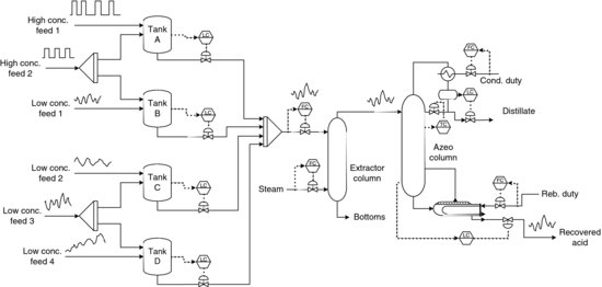
The acid feed is then sent from the tanks to a separation system. This separation system removes water and other impurities to produce the final anhydrous grade product.
The control scheme shown in Figure 10.1 attempts to minimize variance but unfortunately passes along much of the disturbance to the extraction column and the azeotropic column. Consequently, the desired product, which is the bottoms of the azeotropic column, varies significantly in quality.
The long-term focus strategy for the plant involves redesigning the feed inventory system to filter out the high-frequency variations. Figure 10.2 shows the same acid recovery system with a different configuration that helps achieve this long-term focus. All the high-concentration feeds are collected in tank A, while tank B gathers the low-concentration feeds. The feed from tank A is then sent to tank B at a constant rate, thus eliminating some of the problems in variation seen in the short-term focus scheme.
Figure 10.2 Revised acid recovery plant control scheme (Reproduced from [3]. Copyright © 1991 by Greenwood Publishing Group, Inc., Wesport, CT. Reproduced with permission of ABC-CLIO, LLC).

The other major change to the control scheme is in the control systems used for the feed inventory. Level controllers are used on tanks B and C. These level controllers use the capacitance of the tanks to attenuate the fluctuations in feed flow. The feeds to the extraction column and azeotropic column are considerably dampened, resulting in a much more consistent end product.
10.2 Cascaded Units
The dynamics and control of continuous process units that operate as a cascade of units, either in parallel or in series, have been studied extensively for many years [5–7]. A wealth of knowledge is available to help design effective control systems for a large number of unit operations when these units are run independently [6, 8]. This knowledge can be directly applied to the plant-wide control problem if a number of process units are linked together as a sequence of units. Each downstream unit simply sees the disturbances coming from its upstream neighbour.
The design procedure was proposed almost three decades ago [5] and has since been widely used in industry. The first step of the procedure is to lay out a logical and consistent ‘material balance’ control structure that handles the inventory controls, that is, levels and pressures. This hydraulic structure provides gradual and smooth flow rate changes from unit to unit. Thus, flow rate disturbances are filtered so that they are attenuated and not amplified as they work their way down through the cascade of units. Slow-acting, proportional-only level controllers provide the simplest and most effective way to achieve this flow smoothing.
Then product quality control loops are closed on each of the individual units. These loops typically use fast proportional integral controllers to hold product streams as close as possible to specification values. Since these loops are considerably faster than the slow inventory loops, interaction between the two is generally not a problem. Also, since the manipulated variables used to hold product qualities are often streams that are internal to each individual unit, changes in these manipulated variables have little effect on the downstream process. The manipulated variables frequently are utility streams that are provided by the plant utility system, that is, cooling water, steam, refrigerant and so on. Thus, the boiler house will be disturbed, but the other process units in the plant will not see disturbances coming from upstream process units. Of course, this is only true when the plant utilities systems have effective control systems that can respond quickly to the many disturbances that they see coming in from units all over the plant.
As an example of a cascade system, consider a sequence of distillation columns in which the bottoms of the first column feeds the downstream column, shown in Figure 10.3.
Figure 10.3 Cascade system with two distillation columns in series.

Figure 10.3 shows the column with the inventory loops closed. Now that the inventory loops have been closed the product quality loops can be chosen. Each column has two degrees of freedom remaining, reflux and vapour boilup, so some combination of two variables can be controlled in each column, that is, two compositions, two temperatures or one temperature and one flow. Vapour boilup changes require changes in steam flow to the reboiler and also in cooling water flow indirectly through the pressure controller. Both vapour boilup and reflux changes affect the two liquid levels and, therefore, the distillate and bottoms flow rates, but proportional level controllers usually provide effective filtering of these disturbances. Based on these guidelines and the information provided in Chapter 8, the product quality loops can be closed with the specifics of the loops depending on the control objectives.
Since the propagation of the disturbances in such a system is sequential down the flow path, the use of feedforward control on each unit can also help to improve product quality control [7].
It should be noted that the inventory controls can be in the direction of the flow, that is, products come off due to level control, or in the opposite direction, that is, feed is brought in on level control. The same design procedure applies.
10.3 Recycle Streams
If recycle streams exist in the plant, the procedure for designing an effective plant-wide control scheme becomes more complicated. Processes with recycle streams are quite common, but their dynamics are poorly understood at present.
The typical approach in the past for plants with recycle streams has been to install large surge tanks. This isolates the sequences of units and permits the use of conventional cascade process design procedures. However, this practice can be very expensive in terms of capital costs and working capital investment. In addition and increasingly more important, the large inventories of chemicals can greatly increase safety and environmental hazards if dangerous or environmentally unfriendly chemicals are involved.
To demonstrate the principles of plant-wide control for a recycle system, consider the ethylene glycol plant shown in Figure 10.4. Equivalent amounts of water and ethylene oxide are fed to a reactor, as dictated by the reaction stoichiometry, to produce ethylene glycol. The liquid product stream is sent to a distillation column to separate unreacted water and ethylene oxide from ethylene glycol. The unreacted feed is sent back through a recycle loop to the reactor.
Figure 10.4 Ethylene glycol plant.
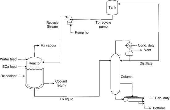
The reactor control problem is a problem of heat management. The reactor is modelled as a continuously stirred tank reactor (CSTR) with a cooling jacket. As such, the reactor temperature can be measured and controlled by adjusting the rate of cooling flow through the jacket until a desired reactor operating temperature is reached.
The problem of distillation control was addressed in Chapter 8. The issue now is how to control the reactor liquid level, the recycle tank liquid level, the recycle flow rate, the ethylene oxide feed flow rate and the water feed flow rate.
The biggest danger in the operation of the whole plant is the ‘snowball effect’ in the recycle [9]. This effect occurs when material accumulates within the recycle loops and cannot be removed. As a result, the plant shuts down. A comparison of two plant-wide control schemes will be made to demonstrate their respective advantages and disadvantages.
The first control scheme involves controlling the level of the reactor by manipulating the flow rate of the reactor effluent. The flow rates of the reactor feed streams are controlled through a ratio controller to meet the required feed ratio. Finally, manipulating the flow rate of the stream to the recycle pump controls the level of the recycle tank. This control scheme is shown in Figure 10.5.
Figure 10.5 Ethylene glycol plant control scheme 1.

To test the weakness or robustness of this first control scheme, a measurement error is introduced to the flow controller manipulating the water feed flow rate. The water feed flow controller receives a signal that is too low. It adjusts the flow to meet the current set point, when in fact it is supplying excess water. The ethylene oxide flow controller moves to match the water feed flow rate through a cascaded ratio controller. The ratio is 1:1 to supply equal amounts of water and ethylene oxide to the reactor.
When excess water is added to the system, the level of the reactor increases. The level controller increases the liquid flow rate leaving the reactor to compensate. Assuming the distillation column separates the ternary mixture almost perfectly, the unreacted ethylene oxide and the excess water are driven overhead into the distillate stream. This stream feeds the recycle tank and thus increases the level. The flow rate of the stream to the recycle pump is increased to compensate. This increased flow is recycled to the reactor and increases the level. The cycle begins again which results in accumulation of water in the system. The recycle stream ‘snowballs’.
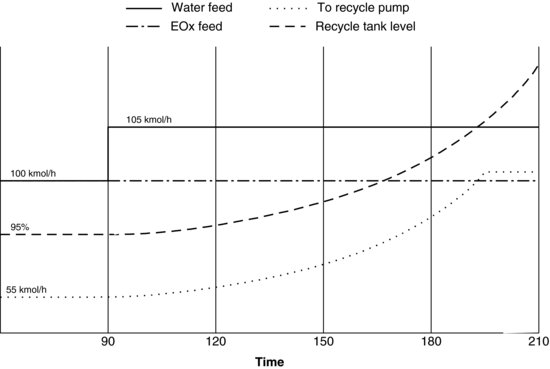
To better illustrate this concept of snowballing, a strip chart was recorded for the appropriate variables in the plant using dynamic simulation (see Figure 10.6). The ethylene glycol plant was set with a recycle tank level of 95% and with a valve size on the stream to the recycle pump which results in almost saturated flow, that is, the valve is almost fully open. The excess water increases the level in the recycle tank, thus opening the valve on the stream to the recycle pump even further until it saturates. The recycle tank then continues to increase, past the 100% point where the tank begins to overflow. The plant must shut down.
Figure 10.6 Control scheme 1 response to a measurement error.
If a positive measurement error is supplied, the flow sensor transmits a flow that is too large. Since the ethylene oxide controller is set up so that the set point is in a 1:1 ratio to the water feed flow rate due to the reaction stoichiometry, too much ethylene oxide enters the system. If this is the case, the excess ethylene oxide reacts with the surplus water in the recycle loop, thus consuming the water and producing ethylene glycol. This reduces the material inventory within the plant until there is only ethylene oxide remaining.
While there are a number of different ways to control this plant, it is helpful to keep in mind two fundamental rules of plant-wide control. These are affectionately known as ‘Luyben's rules’, referring to the original author [10].
With these rules in mind, a new control scheme can be proposed, illustrated in Figure 10.7. This time the stream to the recycle pump is under flow control. In order to control the level of the recycle tank, it is necessary to manipulate the water feed rate. However, with the water feed introduced to the reactor, a considerable amount of dead time is unnecessarily introduced to the system. To overcome this dead time, the water feed is introduced directly into the recycle tank and is used to control the liquid percent level.
Figure 10.7 Ethylene glycol plant control scheme 2.

In order to introduce a similar transmitter error used in the previous control scheme, the recycle tank level controller output is cascaded to provide a set point for a flow controller on the water feed stream. The water feed flow controller uses the measured flow, complete with an error. The ethylene oxide stream is controlled using a composition controller that manipulates the ethylene oxide flow rate to meet a specified composition in the liquid stream leaving the reactor. The liquid level of the reactor will be controlled using the same controller manipulating the flow rate of the liquid leaving the reactor. With these controllers in place, the process flow schematic has been modified. The updated schematic is shown in Figure 10.7.
This control scheme is more robust in the event of a disturbance. The flow rate of the stream to the recycle pump is controlled, preventing any increases in the recycle flow rate. The recycle tank level is controlled by the water feed flow rate. The reactor is still under level control by manipulating the flow rate of the liquid stream leaving the reactor. The ethylene oxide feed flow rate is also manipulated by a composition controller, which measures the exit composition of ethylene oxide from the reactor. This control scheme does not allow for excess ethylene oxide or for excess water in the system, and hence this system cannot snowball.
To demonstrate this system's robustness, the same measurement error can be introduced to the water feed flow rate. The following strip chart (Figure 10.8) shows an introduction of −5 kmol/h error into the sensor transmitting a flow measurement to the water feed flow controller.
Figure 10.8 Control scheme 2 response to measurement error.

With an increase in the amount of water fed to the recycle tank, the level controller adjusts the set point of the water feed flow controller and reduces the amount of water being introduced to the plant. The recycle tank level attains a new operating level. Remember, there will always be offset from the set point due to using only proportional control for the level control. More importantly, notice that there is no accumulation within the system.
10.4 General Considerations for Plant-Wide Control
When considering plant-wide control, a number of questions must be answered:
- What are the primary objectives of the plant?
- Where are the production bottlenecks and constraints?
- Where should the production rate be set?
- Where are the bulk inventories and how should they be controlled?
- Will additional inventory improve the operation and control?
- Will changes in the process design improve the operation and control?
- Where should recycle streams be placed?
- How are the component inventories controlled in these recycle systems?
- Will small changes in a feed cause a very large change in the recycle rate around the system (‘snowball effect’)?
- What are the primary sources of variation?
- What can be done to reduce or eliminate variation at the source?
- How does variation propagate through a plant-wide system?
- What can be done to transfer the variation to less harmful locations?
- How much of the plant-wide operation should be automated and how much should be left for the operator?
Plant-wide design, operation and control is a continually developing area for research. As such, it cannot be summarized simply in one paragraph. For a more in-depth discussion of this topic, refer to the series of papers authored by W.L. Luyben and B.D. Tyreus [9, 11–14] and the book entitled Plant Wide Process Control by W.L. Luyben, B.D Tyreus and M.L. Luyben [10]. More recently Skogestad and co-workers [15,16] have developed a systematic plant-wide control design procedure inspired by Luyben's approach which explicitly incorporates economics in a seven-step procedure that starts with a top-down approach to steady-state economics followed by a bottom-up approach dealing with stabilization and loop pairing. A practical article providing guidelines to ensure smooth plant operation is given by Lieberman [17], and a book on Plantwide Process Control is presented by Erickson and Hedrick [18].
References
1. Downs, J.J. (1993) Plant wide control fundamentals – analysis of material balance systems. Presented at Plant Wide Control Course, Lehigh University, 3–7 May 1993.
2. Vogel, E.F. (1992) Plant wide process control, in Practical Distillation Control (ed. W.L. Luyben), Van Nostrand Reinhold, New York, p. 86.
3. Moore, C.F. (1991) A new role for engineering process control focused on improving quality, in Competing0020Globally Through Customer Value: The Management of Strategic Super Systems (eds M. Stahl and G. Bounds), Greenwood Publishing Group, Westport, CT.
4. Vogel, E.F. (1991) An industrial perspective on dynamic flowsheet simulation. Proceedings of CPC IV, Padre Island, Texas, 17–22 February 1991, CAChE, AIChE, New York, pp. 181–208.
5. Buckley, P.S. (1964) Techniques of Process Control, John Wiley & Sons, New York.
6. Shinskey, F.G. (1996) Process Control Systems: Application, Design, and Tuning, 4th edn, McGraw-Hill, New York.
7. Wilson, H.W. and Svrcek, W.Y. (1971) Development of a column control scheme: case history. Chemical Engineering Progress, 67(2), 45.
8. Considine, D.M. (ed.) (1993) Process Industrial Instrument and Controls Handbook, 4th edn, McGraw-Hill, New York.
9. Luyben, W.L. (1993) Dynamics and control of recycle streams. 1. Simple open-loop and closed-loop systems. Industrial and Engineering Chemistry Research, 32, 466–475.
10. Luyben, W.L., Tyreus, B.D. and Luyben, M.L. (1998) Plant Wide Process Control, McGraw-Hill, New York.
11. Luyben, W.L. (1993) Dynamics and control of recycle streams. 2. Comparison of alternative process designs. Industrial and Engineering Chemistry Research, 32, 476–486.
12. Luyben, W.L. (1993) Dynamics and control of recycle streams. 3. Alternative process designs in a ternary system. Industrial and Engineering Chemistry Research, 32, 1142–1153.
13. Tyreus, B.D. and Luyben, W.L. (1993) Dynamics and control of recycle streams. 4. Ternary systems with one or two recycle streams. Industrial and Engineering Chemistry Research, 32, 1154–1162.
14. Luyben, M.L., Tyreus, B.D. and Luyben, W.L. (1997) Plant wide control design procedure. AIChE Journal, 43(12), 3161–3174.
15. Larsson, T. and Skogestad, S. (2000) Plantwide control: a review and a new design procedure. Modeling, Identification and Control, 21, 209–240.
16. Skogestad, S. (2004) Control structure design for complete chemical plants. Computers and Chemical Engineering, 28(1–2), 219–234.
17. Lieberman, N. (1977) Instrumenting a plant to run smoothly. Chemical Engineering, 84(19), 140–154.
18. Erickson, K.T. and Hedrick, J.L. (1999) Plantwide Process Control, John Wiley & Sons, New York.