
5 Securing the network: The virtual private cloud
- Using virtual private clouds (VPCs) and related resources to configure network access for your AWS resources
- Using network routing and virtual firewalls to protect resources from network-based attacks
- Separating resources into multiple VPCs to isolate them from any misconfigurations or vulnerabilities
- Using services like VPC peering and site-to-site VPN to connect resources in different private networks, without routing traffic over the public internet
In the last three chapters we talked about how to securely configure logical access to your AWS resources through IAM. In this chapter we’re going to move on to controlling network access, primarily through a virtual private cloud, or VPC, and its associated networking resources. Many of the concepts in IAM and VPC are similar. We want to create rules that determine who has what kind of access to our AWS resources. In IAM the rules are policies, which specify actions that can be performed in the API or the console, and these rules are applied to IAM entities (users, groups, etc.) that are authenticated using AWS credentials. In the networking sphere, the rules are concerned with what kind of traffic is permitted into your network and, further, to specific resources within your network. For example, a rule might only permit HTTPS traffic into your network and only on port 443. Rather than being applied to authenticated entities, these rules are, instead, applied based on the source of the traffic. As an example, you might apply the previous HTTPS traffic rule to any traffic originating outside of your network but allow any kind of traffic originating inside your network. While the concepts are similar, the mechanisms for creating and configuring these access rules are completely different. In this chapter we’ll go over the primary VPC networking resources and how to set them up.
Before we dive in, we should talk about why securing your network is important. While there are many different kinds of attacks against network-accessible resources, we’ll look at three of the most common. These are attacks that can be easily prevented by applying the basic principles outlined later in this chapter.
The first type of attack involves an attacker finding and exfiltrating information from a publicly accessible database. Why are these databases left vulnerable? One reason is that setting up secure networks can involve creating a lot of resources, and this is not always done correctly. For example, if you create a web server and a database and don’t create your own security groups, they will both be in the default security group. When you allow public network access to the web server, you will expose your database as well. Later in this chapter we’ll walk through solving this problem by creating secure network rules with security groups and network ACLs.
Another common attack is denial of service. You might have heard of it as DoS or DDoS (distributed denial of service). The usual form of a denial of service attack is flooding your application with tons of fake requests to overload your system and prevent you from fulfilling the real requests. We’ll show in this chapter how you can use AWS networking resources to mitigate certain kinds of denial of service attacks. In the following chapter we’ll look at how to prevent more sophisticated denial of service attacks using next-gen and web application firewalls.
A third attack covered in this chapter is getting SSH access to a web server. When you run a website, you generally open up traffic to the public internet on purpose. But when you do so, you want to make sure you haven’t exposed anything private that might be running on the same server. Often, an EC2 instance is running a web server, and the operator opens up all network traffic to the instance. This allows everyone to view the website, but it also allows everyone to send other kinds of traffic as well, including SSH connections. If you were to run SSH on the default port, use a default user for the operating system, and use a password for authentication, rather than an SSH key, then it would only be a matter of time before an attacker would gain access to the server. In this chapter we’ll see how you can easily create rules that allow public access to your website but don’t allow other kinds of traffic, including SSH.
5.1 Working with a virtual private cloud
The rules we create for controlling network access in AWS apply to various networking resources. To understand how those rules work, we first need to understand the primary networking resources available to us. At the highest level we have the VPC. A VPC represents an isolated network. Within a VPC we have subnets, or individual subnetworks. Most networked resources, like EC2 instances, are attached to a subnet. These subnets can be either public or private, which refers to whether or not resources within the subnet are accessible over the public internet. Traffic between resources within a VPC will be routed through the VPC. That means the traffic does not leave the VPC and is not vulnerable to the same kinds of snooping and man-in-the-middle attacks as if it had gone over the public internet. For this reason it is generally better to keep traffic within a VPC when possible and not route traffic over the public internet. This is such an important concept that several networking resources exist for specifically this purpose, including VPC peering, PrivateLink, and Transit Gateways, which we’ll cover in this and the following chapter.
In addition to VPCs and subnets, there are other networking primitives you should be familiar with:
-
Elastic network interface (ENI)—A virtual equivalent of a network card
-
Elastic IPs (EIP)—A public IPv4 address assigned to your account
-
Internet gateway (IGW)—A resource that allows your network to communicate with the public internet
-
NAT gateway—A resource that allows initiating connections to the public internet from within your network but not the other way around
-
Egress-only internet gateway—The IPv6 equivalent of a NAT gateway
In this section we’ll dive deeper into each of these resources and create a network in our AWS account that looks like figure 5.1. In the following section we’ll expand on that diagram, filling in the faded resources in the diagram, which are the rules that dictate how traffic flows through the network.

Figure 5.1 Many VPCs are composed of public and private subnets. Resources are attached to these subnets via elastic network interfaces and addressable by their elastic IP address.
5.1.1 VPCs
Let’s start with VPCs. As we’ve said, a VPC is a virtual network. If you want to create any networked resources in AWS, you’re going to first have to create a VPC. This is a relatively easy task, as a VPC has only a couple of options. The main one is the CIDR block. This is the range of IP addresses that will be available for use in your network. CIDR stands for classless inter-domain routing, and for our purposes, we’re interested in CIDR blocks, which are a compact notation for describing a range of sequential IP addresses. Here are some example CIDR blocks:
A CIDR block consists of an IP address followed by a slash and a number between 0 and 32. The IP address refers to the smallest IP in the block, and the number after the slash refers to the size of the network. The size of the network is 232 - n IP addresses, where n is the number after the slash. Note that larger numbers correspond to smaller network sizes. A CIDR block ending in /32 would result in only 1 IP address, and a block ending in /24 would result in 256 addresses. Table 5.1 contains the ranges of IP addresses that correspond to the previous sample CIDR blocks.
Table 5.1 Sample CIDR block–to–IP range mapping
Note that the table describes CIDR blocks in terms of IPv4 addresses, but IPv6 addresses can also be used. The difference is that the number after the slash is between 0 and 128, rather than 0 and 32.
There are two important things to consider when choosing a CIDR block for your VPC. The first is that each networked resource that you put into your VPC will be assigned its own private IP address within the CIDR block of the VPC. If you create a VPC with a /24 CIDR block, which has 256 addresses, you won’t be able to put more than 256 resources into that VPC. In fact, AWS actually reserves 5 IP addresses within each subnet, so even if you only had one subnet, you could only put 251 resources into a VPC of size /24. While there is a way to associate an additional CIDR block to your VPC, you should choose a network size large enough to support all of the resources that you plan to put in the VPC. The second point to consider is that overlapping IP ranges create routing issues. For example, Google uses the IP addresses in the block 64.233.160.0/24. If you create a VPC with that same block, then you will end up with hosts that have the same IP address as the Google servers. This makes it very difficult to determine where traffic should be routed. For this reason you should stick to the ranges that have been reserved for private networks, such as 10.0.0.0/8 (10.0.0.0–10.255.255.255) and 172.16.0.0/12 (172.16.0.0–172.31.255.255). In addition, you should not use overlapping ranges for any two VPCs if you plan to route traffic between them.
AWS automatically creates a VPC for you in your account, called the default VPC. A default VPC is created in every region, except in China and GovCloud regions. This default VPC is configured with the CIDR range: 172.31.0.0/16. It is initialized with public subnets and an internet gateway. This makes it easy to get started with many AWS services like EC2, since you can just launch an instance and access it without worrying about setting up these network resources. However, the configuration of the default VPC is likely not the most secure for whatever you’re doing. We won’t use the default VPC and will instead create all of the resources ourselves.
Let’s create our VPC now. We’ll use the AWS CLI create-vpc command, as shown in the following listing.
Listing 5.1 Creating a new VPC
That command creates our VPC. Right now there’s nothing in it, and our network is just a container with a range of IP addresses. The next thing to do is to put subnets inside of our VPC.
5.1.2 Subnets
A subnet is a smaller network within a VPC that contains a partial range of the IP addresses in the VPC. While VPCs reside within an AWS region, subnets reside within a specific availability zone. Subnets are where you can actually place your networked resources. If you have an EC2 instance, you cannot just launch it in a VPC. You must launch it within a specific subnet in that VPC. So if we want to actually do something with our VPC, we should create some subnets. We can use the create-subnet AWS CLI command to do so.
Listing 5.2 Creating two new subnets in an existing VPC
$ aws ec2 create-subnet
   --vpc-id vpc-1234             ①
   --cidr-block 10.0.0.0/26      ②

$ aws ec2 create-subnet
   --vpc-id vpc-1234
   --cidr-block 10.0.0.64/26     ③
① This is the ID of the VPC created earlier.
② This CIDR block covers IP addresses 10.0.0.0–10.0.0.63.
③ This CIDR block covers IP addresses 10.0.0.64–10.0.0.127.
We just created two subnets in our VPC. Our network should now look like figure 5.2.

Figure 5.2 Subnets are composed of CIDR blocks that are subsets of the VPC’s CIDR block. The CIDR blocks of the subnets are nonoverlapping.
We named these subnets Public Subnet and Private Subnet. As previously mentioned, public subnets are ones that can be accessed over the public internet, while private subnets are ones that cannot be. Right now both of the subnets we created are private, as by default there is no connection between a subnet and the public internet. Turning a private subnet into a public subnet requires creating an internet gateway and a route table, which we will do shortly. For right now we’ll leave them both private.
We only created two subnets, and we placed them both in the same availability zone (AZ). This means that if you want to put a resource in this VPC, it will have to go into the same AZ as well. This is fine for our example network, but for production applications it is recommended to create subnets in multiple AZs. Distributing resources across multiple AZs prevents outages in your application in the event of an issue with an availability zone.
5.1.3 Network interfaces and IPs
We mentioned in section 5.1 that instances are attached to subnets. This is done by first attaching an elastic network interface (ENI) to the instance and then attaching that ENI to the subnet. The process of creating and attaching the ENI is abstracted in the process of creating an instance. When you create an instance through the AWS CLI or console, AWS will automatically create the ENI, attach it to the new instance, and attach it to the subnet you specify. So what exactly is an elastic network interface? Elastic network interfaces are the virtual equivalent of an NIC or network card on a physical machine. These ENIs are the connection between networked resources like EC2 instances and your virtual network. In fact, you can attach additional ENIs to your instances, and those ENIs can be in two different subnets. This creates what are called dual-homed instances, which can be visualized in figure 5.3.

In practice, you generally do not need to worry about creating ENIs. Unless you are doing some more advanced networking, ENIs will be created for you with standard settings. For example, when you create an EC2 instance, AWS automatically creates an ENI for the instance and names it eth0. This is the primary network interface for the instance. The primary network interface will be associated with the subnet you chose when creating the EC2 instance.
ENIs are also the mechanism by which IP addresses are associated with networked resources. You can associate an additional IP address with a resource by attaching another elastic IP address to the ENI. The IP addresses are actually their own resource called elastic IPs, or EIPs. As with ENIs, you generally don’t need to create EIPs. When you create an EC2 instance, AWS automatically creates an EIP that is the private IP address for the instance. The EIP is attached to the ENI, which is attached to the instance. The difference with EIPs is that you do not have access to the ones created by AWS. You cannot disassociate the EIP from the network interface and reuse it somewhere else. If you terminate the instance, the EIP will be released. This is important if you want to keep a public IP address, even when an instance is terminated. To do that, you would create a new EIP manually, and then attach that EIP to the elastic network interface on the desired instance. Then, you have the flexibility of moving the EIP around wherever you choose.
Note that the default limit for manually created elastic IPs in your account is five, unless you bring your own IP range. If you want to hold onto more than five IP addresses, you will have to contact AWS support. Getting back to our virtual network, let’s add an EC2 instance to each subnet.
Listing 5.3 Starting an EC2 instance in each of two subnets
$ aws ec2 run-instances
--instance-type t2.micro
--subnet-id subnet-1234     ①
--image-id ami-1234         ②

$ aws ec2 run-instances
--instance-type t2.micro
--subnet-id subnet-5678     ③
--image-id ami-1234 #B
① Replace with the ID of the public subnet.
② Replace with the ID of the AMI you want to use.
③ Replace with the ID of the private subnet.
What appears to be happening is that the instance is being created in the specified subnet. However, we know that behind the scenes, ENI and EIP addresses are being created for us. Check out figure 5.4 for what our network looks like now that we have added all of these resources.

Figure 5.4 Instances are added to subnets. The ENI is the resource that is connected to both the instance and the subnet. Note that the subnet labeled as public is still technically private, as the public internet routing has not been configured yet.
5.1.4 Internet and NAT gateways
Earlier in section 5.1, we defined a public subnet as a subnet that could be accessed from the public internet. By default, our VPC and all of the subnets inside of it are isolated from the public internet. To allow connections between our VPC and the internet, we need a gateway. We’ll talk about a couple of gateways in this section. The first is the internet gateway. An internet gateway, sometimes called an IGW, is a resource that is created in a VPC. When an internet gateway is attached to a VPC, then traffic can be routed from inside the VPC to the internet through that IGW, and vice versa. We can create an internet gateway for our VPC using the create-internet-gateway command, as shown in the following listing.
Listing 5.4 Creating and attaching an internet gateway to a subnet
$ aws ec2 create-internet-gateway      ①
$ aws ec2 attach-internet-gateway     ②
--internet-gateway-id igw-1234        ③
--vpc-id vpc-1234                      ④
① Creates a new internet gateway
② Puts the newly created internet gateway in our VPC
③ The ID of the internet gateway created in the first command
④ The ID of the VPC created earlier
This creates an internet gateway in our VPC. We can see our new network architecture in figure 5.5.

The last step in connecting an instance in our VPC to the public internet is to tell our VPC how to route traffic to the public internet. We’ll see how to do that in the next section.
The default VPC in your account that is created by AWS comes with an internet gateway as well. Additionally, the routing for the internet gateway is preconfigured. This is why you can create an instance in the AWS console and SSH to it immediately without having to configure any network resources.
Another gateway resource is a NAT gateway. A NAT gateway allows you to send traffic out of your VPC to the internet—but not the other way around. This is useful if you have hosts that need to call out to external services, but you do not want anyone to be able to initiate a connection with those hosts. An example could be a build server that pulls from a public GitHub repository and puts build artifacts in S3. The server needs internet access to read from GitHub, but we don’t have a need for access to the build server from the internet. In this case a NAT gateway would work nicely.
A NAT gateway is not an alternative to an internet gateway; they actually work in tandem. If you have an instance that needs internet access, you have two choices. You could route internet-bound traffic to the VPC’s internet gateway, in which case traffic can go in both directions. Or you could route internet-bound traffic to the NAT gateway, in which traffic will be sent to the VPC’s internet gateway and out to the public internet. But traffic cannot go in the other direction. Either way, the internet-bound traffic will go through the internet gateway. Let’s add a NAT gateway to our network, as shown in the following listing.
Listing 5.5 Creating a NAT gateway in an existing subnet
$ aws ec2 allocate-address           ①
    --domain vpc
    --network-border-group us-east-1

$ aws ec2 create-nat-gateway         ②
    --subnet-id subnet-1234          ③
    --allocation-id eipalloc-1234     ④
③ Use the ID of the public subnet.
④ This is the allocation ID returned in the allocate-address call.
There are two important elements to note in that command. The first is that NAT gateways are attached to subnets. This differs from internet gateways, which are attached to VPCs. The second is that we added the NAT gateway to the public subnet. This seems counterintuitive at first, as the public subnet was intended to be for instances that are publicly accessible. If traffic in that subnet was routed through the NAT gateway, then they would not be publicly accessible. Instead, what happens is we route internet-bound traffic in the public subnet to the internet gateway and internet-bound traffic in the private subnet to the NAT gateway residing in the public subnet. The reason we put the NAT gateway in the public subnet is that the NAT gateway needs access to the internet gateway, which we expose in the public subnet but not in the private one. We’ll dive further into this in the next section on network rules and routing. At this point our network looks like figure 5.6.

5.2 Traffic routing and virtual firewalls
In the previous section, we created several networked resources, but we haven’t specified how traffic can actually flow within the network. We’ve said that public subnets need to route traffic to an internet gateway. That routing is done with route tables, and in this section we will look at how this is done. We will also configure two types of virtual firewalls that give us finer-grained control over what traffic is allowed. The two firewalls we’ll use in this section are security groups, which are applied to network interfaces, and network ACLs, which are applied to subnets. In this section we are going to expand the network we’ve been working on in this chapter to include the highlighted items in figure 5.7.

At the end of the section, we will have a common networking setup. You can place instances in the public subnet, and they will be available over the internet. You can place instances in the private subnet, and those instances will not be accessible over the public internet, but they can still call out to the internet if needed. Firewalls will be configured so that if you want to SSH into one of the hosts in the private subnet, you must first SSH into an instance in the public subnet (called a bastion host), and then from there you can SSH into any of the others.
5.2.1 Route tables
A route table defines how traffic is routed throughout your VPC. It is a set of rules that say where traffic should be directed based on the IP address it was sent to. Each of these rules is aptly called a route. Every route consists of two parts: a destination and a target. An example route table with two routes is shown in table 5.2.
Table 5.2 A route table, directing intra-VPC traffic within the VPC. All other traffic is routed to an internet gateway.
The destination of a route is a CIDR block. If traffic is being sent to an IP address within the destination CIDR block, then that traffic is directed to the route’s target. There are many options for the target of a route. One option is a gateway like an internet or NAT gateway. Another option is local, which means the traffic is routed within the same VPC or subnet. There are other possible targets for a route, shown in the following list, but these are the only ones we will talk about in this chapter:
In the example routes in table 5.2, traffic sent to addresses between 10.0.0.0 and 10.0.0.63 is directed to local, which means it is sent somewhere in the same VPC. The second route matches all traffic (recall that 0.0.0.0/0 is all IPv4 addresses) and directs it to an internet gateway.
In our example route table, traffic could potentially match both routes. In that case, traffic is directed to the more specific route (i.e., the one with the larger number after the slash in the CIDR block). So if traffic was sent to the IP address 10.0.0.1, it would match both routes but would be sent to the target of route 1 because that route is more specific.
Whenever you create a VPC, a route table is automatically created and attached to that VPC for you. This route table is called the main route table. It is created with a single route with a destination CIDR block that matches the CIDR block of the VPC, and the target is local. This means that, by default, resources within a VPC can communicate with each other without having to configure additional routing. When you create a new route table, that same local route will automatically be created as well.
Let’s now try setting up the routing resources that will connect our public subnet to the internet gateway. Right now, all traffic in all of our subnets is controlled by the main route table. We could add a route to the main route table that goes to the internet gateway, but that would also apply it to our private subnet, which we do not want to do. Instead, we will create a new route table and associate it with our public subnet. Then, the public subnet will route according to the new route table, and the private subnet will still be routing based on the main route table.
Once we have our route table and it is associated with our subnet, we can add the route to the internet gateway. Recall that a route table is initialized with a local route within the VPC. So there will be two routes. The route table essentially says
At this point, our network looks like figure 5.8, where a route table mapping the public subnet to the internet gateway is created.

Figure 5.8 Using a route table to connect a subnet to an internet gateway. The route table has a default route that directs local traffic within the VPC, and a custom route that directs all other traffic through the IGW.
We also need to create a route to connect our private subnet to the NAT gateway. The process for that is similar. We will create a new route table and associate it with the private subnet. Then, we add a route with a destination of 0.0.0.0/0 and our NAT gateway as the target. This will send all nonlocal traffic to the NAT gateway. And that’s it. Now, the instance in the private subnet can reach the public internet. However, you will not be able to SSH into the instance because the NAT gateway does not allow traffic in that direction. We can visualize the addition of this new route table in our network architecture in figure 5.9.

The last step allowed instances in the private subnet to send traffic to the public internet. However, with the many resources needed to make that happen, it can be hard to see what exactly is happening that allows traffic to flow from the private instance to the public internet. The diagram in figure 5.10 highlights the path through which traffic is routed when a private instance makes a request to a public internet address like 8.8.8.8.
The process by which the traffic is routed is as follows, with each step labeled in fig-ure 5.10:
-
The instance in the private subnet makes a request to 8.8.8.8.
-
The request is routed based on the route table associated with the private subnet.
-
The private subnet’s route table directs the traffic to the NAT gateway.
-
The NAT gateway performs the address translation and forwards the traffic.
-
The NAT gateway is in the public subnet, so the forwarded traffic is routed based on the route table associated with the public subnet.
-
The public subnet’s route table directs the traffic to the internet gateway.
-
The internet gateway handles routing the traffic to the 8.8.8.8 destination over the public internet.

Figure 5.10 The path of traffic as it flows between an instance in a private subnet to a server in the public internet, leveraging NAT and internet gateways
5.2.2 Security groups
A security group is a set of rules that determine what network traffic is allowed in and out of an instance. They are a bit like the networking equivalent of IAM policies. In IAM you might create a policy that allows s3:PutObject and attach that policy to a user. That user can then call the s3:PutObject action. Here you can create a security group that allows outbound TCP traffic on port 443, and you can assign that security group to an instance. That instance is then allowed to initiate TCP connections on port 443.
There are two kinds of rules in a security group, inbound and outbound, and each is made up of three key elements. For outbound rules, these are the destination, protocol, and port range. An example TCP outbound rule might look like what is shown in table 5.3.
Table 5.3 Outbound security group rule allowing TCP traffic on port 443 to anywhere
This rule says that traffic destined for any IP address, using the TCP protocol, on port 443 is allowed. Like IAM, anything not explicitly allowed is disallowed. The destination field can be a CIDR block, like in the example, or it can be a security group. It can refer to its own security group. This is useful if you have a group of instances you want to allow to communicate with each other only. You can put all of the instances in the same security group and create a security group rule that only allows traffic within the security group. The protocol field can be any protocol that has a standard number based on RFC-5237 (see https://tools.ietf.org/html/rfc5237). The most common is TCP, but other frequently used protocols are ICMP (1) and UDP (17). The port range field refers to the receiving port on the destination.
Inbound rules are the same, except instead of a destination they have a source field. The source field again can be a CIDR block or a security group. If you want to allow SSH access to your instance, you can create an inbound rule in your security group that looks like table 5.4.
Table 5.4 Inbound security group rule allowing TCP traffic on port 22 from anywhere
This allows traffic to your instance coming from anywhere, using the TCP protocol (which is what SSH uses), on port 22 (the default SSH port).
When you create a VPC, a default security group is created. The default security group rules are shown in table 5.5.
Table 5.5 Default security group rules
The inbound rule allows all traffic within the default security group. The outbound rule allows all traffic to any destination. If you want to SSH into your instances, you’ll need to add a new inbound rule to your default security group. You can do this by running the AWS CLI commands shown in the following listing.
Listing 5.6 Adding a new outbound rule to a security group
$ aws ec2 authorize-security-group-ingress     ①
      --group-id sg-1234                       ②
      --cidr "0.0.0.0/0"                       ③
      --port 22
      --protocol 6
① This command creates a new inbound rule on a security group.
② This is the ID of the default security group.
③ This CIDR block matches all IPs. This is necessary if you want to be able to SSH in over the internet, and you don’t know what IP you will be calling from.
With this change you can SSH into any instances that are using the default security group.
Let’s go back to the network that we’ve been working on throughout this chapter. We want to allow public access to our instance in the public subnet. The routes and networking resources are all there, but the default security group is preventing us from connecting. One thing we could do is update the default security group to allow inbound access. However, this is not ideal because the default security group is also being used by the instance in the private subnet. We don’t want to modify the existing firewall rules on the instance in the private subnet. Instead, we’ll create a new security group and apply it to the instance in the public subnet.
Listing 5.7 Creating a new security group and applying it to an existing instance
$ aws ec2 create-security-group
   --vpc-id vpc-1234                  ①
   --group-name "PublicAccessSecurityGroup"
   --description "AllowsPublicAccess"
$ aws ec2 modify-instance-attribute
   --instance-id i-1234               ②
   --groups sg-1234 sg-5678            ③
① The ID of the VPC created at the beginning of the chapter
② The ID of the instance in the public subnet
③ The IDs of the default security group and the one created in the first command
Now, both the new security group and the default security group are attached to the instance. An instance can have up to five security groups. The next step is to add an inbound security group rule that allows SSH access from the public internet. The rule was shown in table 5.4 and is repeated in table 5.6.
Table 5.6 Inbound security group rule allowing TCP traffic on port 22 from anywhere
The AWS CLI command to create that is shown in the following listing.
Listing 5.8 Adding a new outbound rule to a security group
$ aws ec2 authorize-security-group-ingress
   --group-id sg-1234
   --cidr "0.0.0.0/0"
   --port 22
   --protocol 6
Now, we should be able to SSH to our instance in the public subnet. We can see how this looks in our network diagram in figure 5.11.

That is everything we need for our network. All of the resources are configured in the way that we prescribed at the beginning of the chapter. We have a public subnet in which we can put instances that are accessible to the public and a private subnet for instances that should be isolated. With the security group rules we just set up, we can use the instance in the public subnet as a bastion to the instance in the private subnet. This just means we cannot SSH into the private instance directly, but we can first connect to the public instance and, from there, connect to the private one. The SSH connection from the instance in the public subnet to the instance in the private subnet is allowed due to the firewall rules on the default security group, which is currently applied to both instances. The default security group rule allows all outbound access and allows inbound requests from any instance that is also using the default security group.
Common attack: SSH access to a web server
Let’s look at one way that we can use security group rules to prevent a common attack. Suppose you have an EC2 instance that is running a web server. The security group for the instance allows all inbound traffic, so anyone can view your website. While checking the logs on the server you notice there are tons of failed attempts to SSH to your instance from IP addresses you do not recognize. This is likely from an attacker trying to brute force access to your server. How can you prevent this?
This can be easily prevented with security groups. The existing security group has the inbound rule shown in table 5.7.
Table 5.7 Permissive inbound security group rule allowing all TCP traffic from all IP addresses
Opening up public access like this is important for allowing people to visit your website, but it is overly permissive. It is like the wildcard policies in IAM that grant excessive permissions. What we can do here is restrict this rule to only the traffic that is necessary for the website. That is typically just TCP traffic on ports 80 (HTTP) and 443 (HTTPS). We can remove the existing rule and replace it with two new ones that look like the ones shown in table 5.8.
Table 5.8 More restrictive inbound security group allowing only web traffic.
Now, everyone can still use your website, but attackers will no longer be able to attempt to SSH into your server. One thing to note is this will remove your SSH access as well. If you need it, you can configure a separate bastion instance for connecting to the web server, as we did earlier in the chapter.
5.2.3 Network ACLs
Network ACLs are virtual firewalls like security groups, but they apply to entire subnets, rather than just to specific instances. Network ACLs can be used instead of security groups when you want to apply the same rules to all instances within a subnet. They can also be used in addition to security groups to provide defense in depth, an additional layer of security in case something goes wrong.
The configuration of network ACL rules is slightly different from security group rules. The order of security group rules does not matter. If there is a security group rule that matches some traffic, then it is allowed. Network ACL rules, on the other hand, are ordered. The rules are evaluated in order, and the first rule that matches the traffic is the one that gets applied. For example, take a look at a sample network ACL inbound rule set in table 5.9.
Table 5.9 Network ACL rules allowing HTTPS traffic into a subnet
The first rule allows HTTPS traffic, while the second denies all TCP traffic. If an HTTPS connection were to be initiated, it would be allowed, since rule #100 is evaluated first, and it allows the traffic.
Another difference between security groups and network ACLs is that network ACLs are stateless, while security groups are stateful. This refers to how responses are handled. Let’s look at a security group, in table 5.10, and a network ACL, in table 5.11, that appear to do the same thing.
Table 5.10 Security group rule allowing outbound HTTPS traffic
Table 5.11 Network ACL rules allowing outbound HTTPS traffic
What both of these virtual firewall configurations amount to are rules that say that all inbound connections are denied, and the only outbound connections that should be allowed are the TCP connections over port 443. With a stateful firewall, like the security group, the response to a permitted outbound request is permitted. In a stateless firewall, like the network ACL, the response is only permitted if there is a rule that permits it. So in the case of this network ACL, you might be able to make an HTTPS request to a website, but the connection will time out, as you will never get a response. That is because the response is being dropped due to the inbound rule of the network ACL. If you want to allow HTTPS traffic originating from your instance with a network ACL, you need to configure both an inbound and an outbound rule that allows it.
Common attack: Exfiltration from a publicly accessible database
Let’s go through an example of using a network ACL to secure an existing network from a common attack. Suppose you have a public subnet with two instances. One runs a web server, and the other runs an open MongoDB database. The database instance has a public IP address assigned to it and is available over the public internet. If someone were to run a port scan on that public IP address, they could find your database and read all of its contents. That attack can be prevented by restricting access, such that only the web server can communicate with the database. Let’s see how we can accomplish that using network ACLs. Suppose the subnet was using a wide-open network ACL with the rules listed in table 5.12.
Table 5.12 Network ACL rules allowing all traffic into and out of a subnet
The easiest way to fix this is to restrict it to allow only the necessary traffic. That necessary traffic is HTTPS on port 443, where the web server is listening. We also need to open up TCP traffic on port 27017, where the MongoDB server is listening, but only within the subnet. We can update the network ACL to use the rules in table 5.13 instead.
Table 5.13 Network ACL rules allowing web traffic originating outside the VPC and traffic to a MongoDB server from within the VPC
These rules lock down our subnet much further. The only traffic allowed in from the public internet is HTTPS traffic on port 443 (by rules #100 and #300). TCP traffic on port 27017 is allowed (by rules #200 and #400) but only to and from 10.0.0.0/24, which is the CIDR block of our subnet. The asterisk rules are catchalls that apply only if none of the other rules applied. These reject all traffic we didn’t specify with an allow rule. Those rules are automatically added. We can update the network ACL in the AWS Console. Open the VPC console, and select Network ACLs under the Security tab. Click the network ACL you want to update, and you can update the inbound and outbound rules. Figure 5.12 shows the network ACL rule-editing screen. Once you’ve made this change, the MongoDB database is no longer available on the public internet.

Common attack: Denial of service
Network ACLs can also be used to defend against simple denial of service attacks. These attacks involve an attacker sending a very large number of requests to your server from a small number of sources. If you notice that traffic is spiking, and most of the traffic is coming from a couple of IP addresses, you can block those IPs using network ACL rules. This has the effect of blocking all traffic coming from those IPs at the subnet level, and those requests will never reach your server. Requests from all other source IP addresses will be allowed. To create the network ACL rule for this, you just have to create an inbound deny rule with a low number on all traffic. For the source of the rule, put the IP address of the attacker in CIDR block format.
There are many kinds of denial of service attacks, and they can be much more sophisticated than this. One variant is a DDOS attack, which involves sending the malicious requests from a very large number of sources. This kind of attack cannot be easily blocked with network ACLs or security groups, as you won’t know what IPs to block, or you won’t be able to block them all. In the next chapter we’ll introduce more sophisticated firewalls and tools like AWS Shield that are better suited for mitigating these types of attacks.
5.3 Separating private networks
So far everything in this chapter has been discussed in the context of a single VPC. While you could manage all of your resources in one VPC, many organizations choose to separate their infrastructure into several VPCs. In this section we’ll discuss the primary reason for using multiple VPCs: network isolation. We’ll also discuss how to create secure connections between resources in different VPCs. If you have a private network outside of AWS, like the LAN in your office or datacenter, at the end of this section we’ll go over a couple of ways to create secure connections between a VPC and your private network.
5.3.1 Using multiple VPCs for network isolation
Recall from chapter 3 that multiple AWS accounts can be used to provide a logical separation between unrelated resources. While you could create the same logical separation just using IAM in a single account, the policies could be complicated and prone to mistakes. Using multiple VPCs for unrelated networking resources is the same. Take a look at figure 5.13, depicting a network using two VPCs.
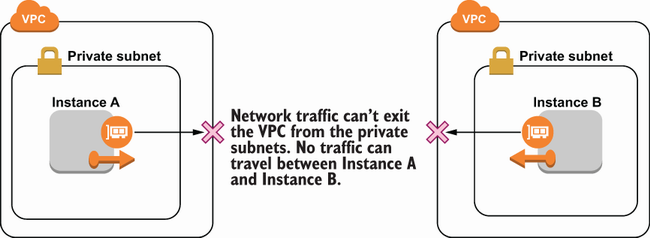
There is a network separation between the two instances in the diagram. Instance A cannot communicate with Instance B. This is beneficial for reducing the blast radius or the potential impact of an attack. Suppose an attacker compromised Instance A. If network access is allowed between the two instances, then the attacker may be able to leverage their position on Instance A to compromise Instance B as well. Since that network access is not allowed due to being in separate VPCs, the attacker’s position on Instance A doesn’t make it any easier to access Instance B.
The same network separation could have been achieved with security groups or network ACLs instead of multiple VPCs. In the case of only two instances, it might have even been easier to use a security group rule. But as networks grow larger, using multiple VPCs becomes a very convenient way to separate resources without the risk of a mistake. See figure 5.14, which compares preventing access between instances using a single VPC versus multiple VPCs.

Figure 5.14 Comparison of blocking traffic between instances using multiple VPCs and security groups only. It can be achieved by either method, but multiple VPCs provide an additional level of security.
5.3.2 Connections between VPCs
While using two VPCs is a good way to prevent access between resources, there are times in which you need resources in separate VPCs to communicate. One reason is that a VPC can only be in a single region. If you have resources in several regions, then they’ll have to be separate VPCs. VPCs are also specific to a single AWS account. If you use multiple accounts and need connectivity between them, you can’t just put all of the resources from each of the accounts in the same VPC.
One way to achieve connectivity between two VPCs is by routing traffic over the public internet, using the tools we’ve already discussed in this chapter. You could follow the steps in section 5.1.4 to create an internet gateway in both VPCs. Then, use the information from section 5.2 to configure the routing and firewall rules to allow the networked resources to send and receive traffic from the internet gateway. Figure 5.15 shows how this network setup might look. However, this is not the ideal situation. If certain firewall rules aren’t configured correctly, you risk allowing access to your resources to anyone on the public internet. Additionally, public internet traffic between resources in separate regions is not guaranteed to stay within the AWS network. That introduces its own security and availability concerns.

Figure 5.15 Connecting instances in different VPCs over the public internet. All traffic from the public internet is allowed into the VPC and is only blocked at the security group or network ACL level.
A better way to connect between resources in separate VPCs is through VPC peering connections. A VPC peering connection is a resource that allows you to route traffic between resources as if they were in the same VPC. A basic VPC peering setup is shown in figure 5.16.
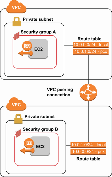
Figure 5.16 VPC peering connections allow network communication between resources in separate VPCs without the need for exposing public internet access.
Using a VPC peering connection, we can connect between VPCs without having to allow public internet traffic in and out of our VPC. Let’s walk through setting up a VPC peering connection. Before we get started, we need two VPCs to peer. Let’s create two VPCs, each with a single subnet and a single instance.
Listing 5.9 Creating two new VPCs with nonoverlapping CIDRs to be peered
① Create two VPCs for peering.
② Use nonoverlapping CIDR ranges for the VPCs.
To create a peering connection between two VPCs, they must not have overlapping CIDR blocks.
Listing 5.10 Creating a subnet in each of the two VPCs that will be peered
$ aws ec2 create-subnet
   --vpc-id vpc-1234          ①
   --cidr-block 10.0.0.0/24

$ aws ec2 create-subnet
   --vpc-id vpc-5678          ②
   --cidr-block 10.0.1.0/24
① Replace with the ID of the first VPC.
② Replace with the ID of the second VPC.
Listing 5.11 Starting an EC2 instance in each of the two newly created subnets
$ aws ec2 run-instances
      --instance-type t2.micro
      --vpc-id vpc-1234             ①
      --subnet-id subnet-1234        ②
$ aws ec2 run-instances
      --instance-type t2.micro
      --vpc-id vpc-5678             ③
      --subnet-id subnet-5678        ④
① Replace with the ID of the first VPC.
② Replace with the ID of the first subnet.
③ Replace with the ID of the second VPC.
④ Replace with the ID of the second subnet.
Once we have those resources, we can create the peering connection between them. This involves the following steps:
Start by navigating to the VPC console. From there, select Peering Connections from the sidebar, and click Create Peering Connection. You will be prompted for the IDs of the VPCs you just created, as seen in the screenshot of the Create Peering Connections UI in figure 5.17.

The next step is to accept the newly created peering connection. In the VPC console, you can do this by clicking the peering connection request and selecting Actions. From the Actions menu, choose Accept Request, and confirm the action. These actions could also have been completed using the CLI instead of the management console. VPC peering connection requests can be created with the create-vpc-peering- connection command under the EC2 service. You can then accept those requests with the accept-vpc-peering-connection command.
The final step is to create the routes that direct traffic between the VPCs. We’re going to add a route in the first VPC with a peering connection as a target and the CIDR block of the second VPC as a destination. We’ll do the same thing in the second VPC with a route that has the first VPC’s CIDR block as the destination. This can be done through the VPC console or using the AWS CLI. The routes we need to create are shown in table 5.14.
Table 5.14 Routes to create for a VPC peering connection
Once these routes are created, then traffic can flow between the VPCs privately. You can verify this by trying to ping the private IP address of an instance in the second VPC, using an instance in the first VPC.
At the beginning of the section, we mentioned that common reasons for needing connections between VPCs were due to using multiple regions or accounts. Peering connections can be created for VPCs in different regions (called inter-region peering connections) or different accounts. This solves the issue of running connections over the public internet in these situations. Inter-region VPC peering connections also guarantee that traffic stays within the AWS network as it goes between your cross-region resources.
5.3.3 Connecting VPCs to private networks
VPC peering connections primarily solve the problem of routing traffic privately, rather than over the public internet. But peering connections only work for VPCs. What if you have servers running in your garage, office, or datacenter? The idea still holds that routing those connections privately is better than routing them through the public internet. If some of your servers aren’t in AWS, you can’t use peering connections for that, but there are other tools you can use. The easiest one to use is AWS Site-to-Site VPN.
Site-to-site VPN is a service that lets you create a VPN tunnel between your non-AWS network and a VPC in your AWS account. When you set up site-to-site VPN for your VPC, you create a virtual private gateway in your VPC. The virtual private gateway is similar to an internet gateway, but the traffic going in and out is restricted to going only through the VPN tunnel between your VPC and your private network. To enable the site-to-site VPN on your private network, you need to configure your router with the VPN settings. The steps to configure the VPN will vary based on your routing device, but AWS provides examples for the most common devices. Once you’ve set up the virtual private gateway and configured your private network, the site-to-site VPN is ready to go. You can route traffic through your virtual private gateway to your private network using route tables the same way you would for an internet gateway. The virtual firewall settings for security groups and network ACLs will behave the same as well. For an overview of how traffic flows between your private network and a VPC with site-to-site VPN, see figure 5.18.
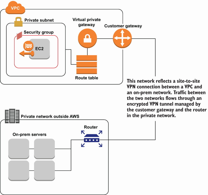
Figure 5.18 Sample diagram of a site-to-site VPN connection between an on-premises network and a VPC
Another option for privately connecting an on-premises network to a VPC is AWS Direct Connect. Direct Connect is a service that allows you to create a direct line between your on-premises network and the AWS network. As opposed to using a VPN, traffic is sent straight to AWS without any hops in between. Direct Connect is more expensive and difficult to set up than site-to-site VPN, but it can be a better option when you are transferring large amounts of data quickly, and you are limited by the bandwidth of your VPN connection. For more information on setting up AWS Direct Connect, see the documentation at https://aws.amazon.com/directconnect.
Summary
-
Network access controls in VPCs are similar to the logical access controls of IAM, but they are configured in completely different ways.
-
Using VPCs and other networking resources allows you to control network access to and from your AWS resources.
-
Configuring built-in virtual firewalls like security groups and network ACLs allows you to lock down your network and protect against unauthorized access to your resources.
-
Putting resources into separate VPCs isolates them from each other and prevents a compromised resource from accessing other resources.
-
Setting up a peering connection between VPCs allows you to isolate resources in separate VPCs, while still allowing for private connections between them.
-
Using VPC peering, site-to-site VPN, or Direct Connect allows you to connect to a resource without residing in the same VPC and also avoids the risks associated with sending traffic over the public internet.