
16
Video Noise and Compression Artifacts
Chapter Outline
Video or image data can contain noise: this can be introduced by the sensor, during transmission or during storage. Imperfections on old film can cause noise when it’s converted to digital video form – this tends to be a random type of noise. Noise reduction processing or filtering is a process that can reduce or eliminate this effect.
16.1 Salt-and-pepper Noise
Salt-and-pepper noise occurs when individual pixels or small areas of the image have high contrast, or are very different in color or intensity from their surrounding pixels or areas. This pixel or area is visually noticeable and means that the image contains dark and white dots – which is why it’s referred to as salt-and-pepper noise. Sources include particles of dust inside the camera and defective CCD elements.
Filtering can be employed to counter this type of noise. A linear filter with a low-pass characteristic can be employed to smooth sharp transitions in both vertical and horizontal directions. This type of filtering is very effective, but it will remove, or at least reduce the amount of, all high-frequency spatial content. Thus sharp edges will also be smoothed out with the resultant blurring, or loss of sharpness of the image.
Alternatively, another type of filter, known as the median filter, is often used. A conventional digital filter is a linear combination, or weighting of nearby pixels, for the new adjusted value for a given pixel. The right combination of weighting, or coefficients, results in a smoothing, or low pass, effect.
The median filter is a non-linear filter, and, unlike a conventional digital filer, does not require any multipliers. The median filter operates by taking a group of pixels in a certain area, for example a 3 × 3 pixel area. The new pixel value in the center of that area is the median, or middle value, of the nine pixel values. There is no weighting or linear combination. The entire image is processed by shifting the 3 × 3 pixel area in vertical and horizontal increments. If a single pixel is very different from all surrounding pixels, it will never be the median value, and will be filtered out by the median filter. This is shown in the black and white pixel image in Figure 16.1.

Figure 16.1 Median filter of random noise.
However, consider a sharp vertical edge: this will be smoothed or softened by a low pass digital filter. But with a median filter, the same sharp transition can be preserved, as shown in Figure 16.2.

Figure 16.2 Median filter with sharp edge.
Alternate pixel areas can be used for median filtering, as shown in Figure 16.3. The operations are the same – the output pixel value at the center of the pixel area is the median, set equal to the value of the pixel value in the middle after all the pixels have been sorted by value. As the median filter is shifted across the image, it always operates on the original pixel data. The output of the median filter forms a new image, built up pixel by pixel using the median filter. The median filter is but one type of filter that can be used. There are other types of more complex filtering that can be applied.
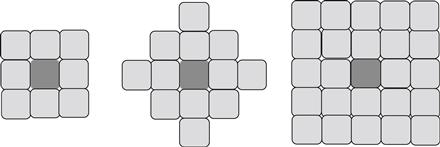
Figure 16.3 Examples of median filter area.
Removal of salt-and-pepper noise also has a beneficial effect upon subsequent video compression. This type of noise creates high frequency, which needs to be encoded using high-frequency DCT coefficients, requiring portions of the compressed bit-stream to be wasted in representing this noise.
16.2 Mosquito Noise
Video compression and decompression can result in other types of video distortion or artifacts. One common distortion happens near sharp or crisp edges of objects in MPEG and other video frames that use the discrete cosine transform (DCT). It occurs during decompression when the decoding engine has to approximate the discarded data by inverting the transform model. Known as mosquito noise, it manifests as random aliasing in these areas and appears as ringing around sharp edges. It is caused by the removal of high-frequency coefficients during compression quantization, as shown in Figure 16.4. As TVs and monitors get larger, mosquito noise and other artifacts become more prominent.

Figure 16.4 Mosquito noise example.
Mosquito noise tends to occur around text or letters in an image, or with computer-generated video objects with very sharp transitions. Mosquito noise looks like a cloud around the edges of text and computer generated graphics.
Reducing this artifact requires spatial image analysis. Each region, or even each pixel, must be classified into categories such as edge, texture, flat and artifact regions. Across the temporal dimension, or sequential video frames, motion prediction can also be used to help distinguish moving edges due to objects in motion. A combination of this analysis is used to identify artifact regions and apply filtering techniques to reduce in those regions. This tends to be an adaptive process.
Sometimes the only choice may be to accept the noise, or to filter and have blurring occur. When motion is very rapid, filtering may be the better choice, even if blurring is introduced, as the blurring is often not as obvious in fast motion scenes. And on some occasions, the motion is too rapid for the temporal rate (frame per second), violating the sampling theorem, so that some form of degradation due to the aliasing is inevitable.
16.3 Block Artifacts
Block artifacts are a discernable visual blocking effect on the video which can occur at the 8 × 8 boundaries used in the DCT. This is due to several effects, one of which is differing DC coefficients. In some cases, this effect can become visually objectionable, as shown on the left side of Figure 16.5. Each block can also have varying amounts of quantization, depending upon how many AC coefficients have significant amplitude. When high quantization is used, the DCT averages each 8 × 8 block approximately, making it roughly appear like a group of pixels, each of size 8 × 8. These effects can become even more pronounced in scenes with high motion, such as sports broadcasts.
A common solution is to filter at the block edges, to smooth the transition between blocks. This filter must by necessity be of short order, and apply to only one or two pixels at the 8 × 8 boundary. This filter is adaptively applied and is part of the H.264 decoder in some profiles. One of the factors driving it is the quantization level: at high quantization levels, blocking artifacts are more predominant, and deblocking filtering is needed. Another factor is video content: a smooth region will have a stronger blocking effect compared to an area with a high-activity video level. The smoother region will require more aggressive deblocking filtering.
The H.264 deblocking filter is designed to avoid the requirement for multipliers, instead choosing coefficients that can be implemented using shift and adds, reducing the hardware requirements.
Figure 16.5 shows the image prior to deblocking, and then after application of the deblocking filter. All of these processes can be applied to individual color planes, or to luma and chroma planes.

Figure 16.5 Deblocking filter example.