12.3. MFSM: An Architectural Middleware
This section is an example-based, code-level tutorial on the use of the MFSM architectural middleware for implementing image-stream manipulation applications designed in the SAI style. It begins with a brief overview of the MFSM project and its implementation of SAI. Design and implementation of applications for image-stream manipulation is then explained in detail using simple examples based on those used in the online MFSM user guide. A first example illustrates application setup and cleanup, and application graph elements instantiation and connection. The development of specialized nodes is explained with a study of the implementation of a generic image data structure (object of an open source module). The use of this node type in a specialized process is explained with a study of the implementation of a custom cell used in the first example. Finally, a more complex example illustrates shared memory access for incremental computations along the time dimension.
This section constitute an image-oriented, self-contained complement to the online user guide [12].
Disclaimer
The code appearing in this section was developed by the author and is part of open source modules and examples released under the GNU Lesser General Public License [1]. They are available for download on the MFSM Web site [12]. This code is provided here in the hope that it will be useful, but without any warranty—without even the implied warranty of merchantability or fitness for a particular purpose. Complete license information is provided in the downloadable packages.
12.3.1. MFSM overview
MFSM [12] is an architectural middleware implementing the core elements of the SAI style. MFSM is an open source project, released under the GNU Lesser General Public License [1]. The goal of MFSM is to support and promote the design, analysis, and implementation of applications in the SAI style. This goal is reflected in the different facets of the project.
- The FSF library is an extensible set of implementation-level classes representing the key elements of SAI. They can be specialized to define new data structures and processes or encapsulate existing ones (e.g., from operating system services and third-party libraries).
- A number of software modules regroup specializations implementing specific algorithms or functionalities. They constitute a constantly growing base of open source, reusable code, maintained as part of the MFSM project. Related functional modules may be grouped into libraries.
- An evolving set of example applications illustrates the use of FSF and specific modules.
- An evolving set of documents provides reference and example material. These include a user guide, a reference guide and various tutorials.
Figure 12.20 shows the overall system architecture suggested by MFSM. The middleware layer provides an abstraction level between low-level services and applications, in the form of SAI software elements. At the core of this layer is the Flow Scheduling Framework (FSF) [13, 17], an extensible set of foundation classes that implement SAI style elements. The generic extensible data model allows encapsulation of existing data formats and standards, as well as low-level service protocols and APIs, and makes them available in a system where they can interoperate. The hybrid shared repository and message-passing communication and parallel processing model supports control and asynchronous, concurrent processing and synchronization of data streams. The application layer can host a data-stream processing software system, specified and implemented as instances of SAI components and their relationships.

In its current implementation, the FSF library contains a set of C++ classes implementing SAI elements: the source, the nodes and pulses, the cells, the filters, the handles. It also contains classes for two implementation-related object types: the factories and the System. A brief overview of each object type is proposed below. An online reference guide [12] provides detailed interface description and implementation notes for all the classes defined in the FSF library.
Source
The source class is fairly simple. It holds a single passive pulse and keeps a list of pointers to connected cells. Note that connectors are not implemented as objects, but simply lists of pointers in the components. This results from the simplicity of the role played by connectors in the SAI style. In particular, they do not perform any computation. Sources also perform garbage collecting on their passive pulse when notified of a structural change by a connected cell.
Nodes and pulses
The FSF library contains a base node class that implements connectivity elements for building hierarchical structures. Specialized node classes, encapsulating or implementing specific data structures, are derived from the base class. In FSF, from the base node class are derived two specific classes for active and passive pulse respectively. These serve as root nodes for active and passive pulse, which are node hierarchies. Another node specialization is provided in FSF that implements nodes holding atomic type values (integer, floating point, boolean, string, etc.). These are called TypeNodes, and are implemented as template instances of a template class, itself derived from a non-template TypeNodeBase class (to allow undetermined pointers to a TypeNode object).
Cells
The FSF library contains a base cell class that implements cell-cell and cell-source connectivity mechanisms (lists of pointers). It also implements all the computation associated with the parallel processing of active pulses. In MFSM, in each cell, each active pulse is processed in a separate thread. Each passive filtering operation is also carried in a separate thread. As a result, some precautions must be taken for concurrent data access. Thanks to inheritance and virtual functions, when implementing a specialized cell derived from the base cell, only the specific computation must be coded, in an overloaded process, virtual-member function. All the events leading to the call to this process function, including filtering, will be automatically performed. A cell can be active or inactive. For efficiency purposes, passive filtering occurs only when the cell is activated (activation fails if passive filtering fails) and when explicitly notified by the source after a cell notified the source of a structural change in the passive pulse.
Filters
Two sets of classes are implemented for active and passive filters respectively. For each, a template class derived from a non-template base class provides support for instantiating filters corresponding to any node type. The non-template base class allows pointers to undetermined filters (e.g., in cells). The filter objects also implement the filtering functionality. Active filtering instantiates and returns a list of active handles and passive filtering instantiates and returns a list of passive handles.
Handles
Two sets of classes are implemented for active and passive handles respectively. Active handles simply provide a pointer to a node in an active pulse. An optional handle ID, inherited during the filtering operation, allows identification of the node with respect to the filter. Passive handles play the additional role of locks for node deletion and garbage collecting (not required in active pulses). When a cell removes a node, it does not destroy it, but marks it as deleted so it is not used in subsequent filtering operations. The cell must notify the source, which in turn notifies all connected cells to refilter the passive pulse, and initiates a garbage-collecting process, which physically deletes the node when is it free of handles from ongoing process.
Factories
Class factories are used to instantiate objects at runtime, whose type is not known at compile time. Since cells and nodes constitute extensible sets of specialized object types derived from respective base classes, Cell and Node factories are necessary for instantiating cells and nodes at runtime and modifying application graphs dynamically. Node factories also allow instantiation of filters for the corresponding node type.
System
By convention, any application using FSF must have a single instance of the System type, a pointer to which is available as a global variable, defined in the FSF library. This object provides the reference clock and holds the lists of node and cell factories available for building application graphs. In order to use a module in an application, its node and cell factories must be declared and registered with the system instance.
12.3.2. A first image manipulation example
The online MFSM user guide [12] describes a simple program (called ex1) that generates a stream at a given frame rate and displays the timestamp of each pulse in both ms and h/m/s formats. The example in this section performs a similar task, but instead of being written to the standard output, each formatted timestamp string is written into a newly created image (using Intel's OpenCV [2]). This first example is called eximg1.
Application design and specifications
Before building a design and after identifying the system requirements, it is useful to know what building elements are available. This simple application involves a (single) stream, so the first concern is the origin of the stream. FSF contains a fundamental cell type that generates empty pulses at a given frame rate. It is called Pulsar, and Table 12.2 shows its specifications. It does not have any input. It has one parameter, of integral type, whose value is the time delay between two consecutive output pulses.
| fsf::CPulsar (fsf::CCell) | FSF_PULSAR |
|---|---|
| Active filter | (no input) |
| Passive filter | [FSF_INT32_NODE "Pulse delay"] |
| Output | (FSF_ACTIVE_PULSE "Root") |
In this section, it is assumed that a cell is available that is capable of looking up the timestamp of each incoming active pulse, creating an image, and printing the formatted timestamp in the image. The actual implementation of this cell is addressed later, in the Section 12.3.3. Table 12.3 shows the cell specifications.
| myspace::CMyCellImg (fsf::CCell) | MY_CELL_IMG |
|---|---|
| Active filter | [FSF_ACTIVE_PULSE "Root"] |
| Passive filter | [FSF_PASSIVE_PULSE "Root"] |
| Output | (IMAGE_IMAGE "Image") |
The open source Display Module defines and implements a cell that can display an image into a window. Table 12.4 shows the ImageDisplay cell specifications.
| display::CImageDisplay (fsf::CCell) | IMAGE_DISPLAY |
|---|---|
| Active filter | [IMAGE_IMAGE "Image"] |
| Passive filter | [FSF_FLOAT32_NODE "Display zoom"] |
| Output | (no output) |
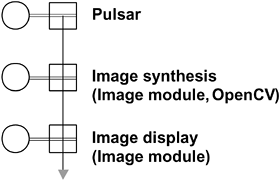
Given these elements, it is now straightforward to formulate a design for eximg1 from one instance of Pulsar, one instance of MyCellImg, and one instance of ImageDisplay. Figure 12.21 shows the resulting conceptual application graph.
Figure 12.21. Conceptual level graph for the first image manipulation example, eximg1.
The next few sections explain in detail how to code the simple application in C++: setting up the system, building and running the application graph, and cleaning up the objects allocated.
Getting started
The first mandatory step in using the FSF library is to allocate the unique system object that provides the reference clock and holds the node and cell factories available. The nodes and cells defined in each module used must be registered. Factories can be registered in any order. They are not necessary for preceded application graphs, although they are used by the scripting module functions (see below). Factories are necessary for dynamic, runtime application graph building and/or modification, which is out of the scope of this introduction. Each module is required to declare and implement a function called RegisterFactories for registering factories in the system for all nodes and cells implemented in the module.
// create the system
fsf:: AllocateSystem() ;

// register system factories
fsf::RegisterFactories();

// register module factories
image::RegisterFactories();
display::RegisterFactories();

// register myspace factories
myspace::RegisterFactories();
Building the graph
A scripting module (namespace scripting) provides shortcut functions to instantiate sources and cells, instantiate nodes and place them in source pulses, and connect cells to other cells and to sources. The convention followed in the parameter order for stream connections is to plug a downstream cell into an upstream cell. The name "scripting" comes from the fact that the functions provided by this module are coding equivalents of user actions in an interactive system. In particular, the scripting module uses aspects of the MFSM implementation that are related to dynamic system evolution, such as class factories. Note that the scripting module itself does not implement any node or cell class and thus does not register any factory (there is no scripting::RegisterFactories).
The code for building an application graph instantiates and connects all the elements of the conceptual graph. In this simple example, the graph can be divided into three functional parts: the pulsing unit built around the Pulsar instance, the image synthesis unit built around the MyCellImg instance, and the display unit built around the ImageDisplay instance. Each subgraph in this case corresponds to one source and one cell (minimal computing units).
Each minimal unit, consisting of one cell and one source whose pulse contains the cell's parameters, can be coded following these steps:
- – Instantiate the source.
- – Instantiate the parameter node(s). Each node is placed in the source's passive pulse hierarchy. Optional steps for each node include setting its name and data member initial values.
- – Instantiate the cell. Optional steps include setting the output base name, the active and passive filters. The cell is then connected to its source and to the cell directly upstream on the active stream, if any.
These principles can be used as guidelines and adapted to code any graph. The following code builds the graph for the example, first the pulsar unit, then the image synthesis unit, and finally the image display unit. Successful instantiation of all graph elements is checked, as failure to register the appropriate factories will result in the failure to instantiate a given cell or node.
// build graph
bool bSuccess=true;

/////////////////
// Pulsar unit //
/////////////////

// create the source
fsf::CSource *pPSource=new fsf::CSource;
bSuccess &= (pPSource!=NULL);

// parameter node: pulse delay
fsf::Int32Node *pPulseDelay =
  static_cast<fsf::Int32Node*>(scripting::CreateNode(
    std::string("FSF_INT32_NODE"),pPSource->GetPulse()));
bSuccess &= (pPulseDelay!=NULL);
if(bSuccess)
{
  // set name
  pPulseDelay->SetName(std::string("Pulse delay"));
  // set parameter values
  long nPulseDelay=static_cast<long>((1000.0f/fPulseRate)-l);
  pPulseDelay->SetData(nPulseDelay);
}

// cell
fsf::CCell *pPcell =
  static_cast<fsf::CCell*>(scripting::CreateCell(
   std::string("FSF_PULSAR")));
bSuccess &= (pPcell!=NULL);
if(bSuccess)
{
  // connect with source
  scripting::ConnectSource(pPcell,pPSource);
}

//////////////////////////
// Image synthesis unit //
//////////////////////////

// create the source
fsf::CSource *pMySource=new fsf::CSource;
bSuccess &= (pMySource!=NULL);

// cell
fsf::CCell *pMyCell =
  static_cast<fsf::CCell*>(scripting::CreateCell(
   std::string("MY_CELL_IMG")));
bSuccess &= (pMyCell!=NULL);
if(bSuccess)
{
  // connect with source
  scripting::ConnectSource(pMyCell,pMySource);

  // connect with Pcell
  scripting::ConnectUpstreamCell(pMyCell,pPcell);
}

//////////////////
// Display unit //
//////////////////

// create the source
fsf::CSource *pDisplaySource=new fsf::CSource;
bSuccess &= (pDisplaySource!=NULL);

// parameter node: display zoom
fsf::Float32Node *pDisplayZoom=static_cast<fsf::Float32Node*>(
  scripting::CreateNode(
    std::string("FSF_FLOAT32_NODE"),pDisplaySource->GetPulse()));
bSuccess &= (pDisplayZoom!=NULL);
if(bSuccess)
{
  // set name
  pDisplayZoom->SetName(std::string("Display zoom"));
  // set parameter values
  pDisplayZoom->SetData(1.0f);
}

// cell
fsf::CCell *pDisplayCell =
  static_cast<fsf::CCell*>(scripting::CreateCell(
    std::string("IMAGE_DISPLAY")));
bSuccess &= (pDisplayCell!=NULL);
if(bSuccess)
{
  // connect with source
  scripting::ConnectSource(pDisplayCell,pDisplaySource);

  // connect with Pcell
  scripting::ConnectUpstreamCell(pDisplayCell,pMyCell);
}

// Check everything went OK...
if(bSuccess==false)
{
  cout << "Some elements in the graph could not be instantiated."
       << endl;
  return (-1);
}
Running the graph
Once the graph is completed, the cells must be activated. The Pulsar instance is the origin of the active stream and starts generating empty pulses as soon as it is activated. The MyCellImg instance, once activated, will process incoming pulses in parallel, asynchronously. The ImageDisplay instance will render the images produced by the MyCellImg instance on the screen. The cells can be started in any order.
// run the cells
pMyCell->On();
pPcell->On();
pDisplayCell->On();
Although this aspect is not evident in this simple example, cells can be turned on and off at any time during the execution of the application, elements (sources and cells) can be connected and disconnected at any time, and new ones can be created and existing ones destroyed at any time.
Because the Display Module relies on the Microsoft Windows operating system to display images on the screen, the console application must explicitly provide for a mechanism to dispatch and process messages for the display window. The following code serves this purpose. At the same time, the GetAsyncKeyState function is used to check whether the Q key is pressed to exit the loop.
// message loop for windows
// + check for 'Q' key (VK_Q id 0x51) pressed
MSG msg;
while(((GetAsyncKeyState(Ox51)&0x1)==0)
      &&::GetMessage( &msg, NULL, 0, 0))
{
  ::TranslateMessage( &msg );
  ::DispatchMessage( &msg );
}
This is the only MS Windows specific code in the application.
Clean-up
The following code stops the cells, disconnects and destroys the different elements instantiated when building the graph, and finally deallocates the unique global FSF system instance. The scripting module provides high-level functions to disconnect cells and source.
// Stop the cells
pPcell->Off();
pMyCell->Off();
pDisplayCell->Off();
// Clean up
scripting::DisconnectSource(pPcell);
scripting::DisconnectStream(pPcell);
delete pPcell;
delete pPSource;

scripting::DisconnectSource(pMyCell);
scripting::DisconnectStream(pMyCell);
delete pMyCell;
delete pMySource;

scripting::DisconnectSource(pDisplayCell);
scripting::DisconnectStream(pDisplayCell);
delete pDisplayCell;
delete pDisplaySource;

// Deallocate system
fsf::FreeSystem();
Running the program
The example implementation allows specification of the pulse rate on the command line (the default rate is 15 Hz). Figure 12.22 shows a screen shot of the display window.
12.3.3. Custom elements
If one of the goals of MFSM is to allow rapid design and development of applications from existing modules, one of its main strengths is to allow easy specification and implementation of custom elements that will interoperate seamlessly with existing or third-party components.
12.22. Screen shot of the display window for eximg1.

The example developed in the previous section, eximg1, makes use of an instance of a cell type called myspace::MyCellImg, whose task is to look up the timestamp of each incoming active pulse, format it, and print the resulting string into a newly created image. In this section, the design and implementation of specialized SAI elements (nodes and cells) is illustrated on the customized elements of eximg1. First, the generic image node image::CImage implemented in the open source Image Module is described. Then, the design and implementation of the myspace::MyCellImg cell type, which makes use of the image::CImage, are detailed step by step.
A custom node type: image::CImage
One solution when designing the image node was to encapsulate an existing image structure. Unfortunately, each image processing library comes with its own image structure. Committing to a given library might prevent access to other libraries and prove restrictive in the long term. The image node defined in the Image Module provides a minimum representation to ensure its compatibility with existing image structures (in particular, that used in OpenCV). However, the image node does contain any field specific to particular image formats to ensure the widest compatibility. When needed, more specific image nodes may be derived from this base image node for leveraging specific library features. Because of inheritance properties, these specialized image nodes will be usable with all processes defined for the base image node.
Any node type specialization must be derived from the base node fsf::CNode or a derived node. A node type is characterized by an identification string (used to link it to its factory). A complete node type description includes a list of data members and member functions, and a short description of its semantics.
The image node is derived from the character buffer node defined in the FSF library. An image buffer is indeed a character buffer. The smallest set of parameters needed to make the character buffer usable as an image buffer are the image width and height, the number of channels, and the pixel depth. Since some libraries require data-line alignment for optimal performance, the actual aligned width (width step) must also be stored. A utility-protected member function is used to compute the aligned width.
class CImage : public fsf::CCharBuffer
{
protected:
  int m_nNbChannels; // Number of channels
  int m_nDepth; // Pixel depth IMAGE_DEPTH_*

  int m_nWidth; // Image width
  int m_nHeight; // Image height
  int m_nWidthStep; // Aligned width (in bytes)

  // utility protected member function
  int ComputeWidthStep(bool bNoAlign=false);
Any custom node class must implement a number of constructors: the default constructor, all the constructors defined in the the base node class (these must define default values for the local data members), additional constructors for specifying local data members' initial values, and the copy constructor. When necessary, the virtual destructor must also be overloaded.
public:
  // Default constructor
  CImage() : CCharBuffer(),
    m_nNbChannels(3), m_nDepth(IMAGE_DEPTH_8U),
    m_nWidth(0), m_nHeight(0), m_nWidthStep(0) {}

  // Constructors with default values for local data members
  CImage(fsf::CNode *pParent, DWORD dwTime=0)
    : CCharBuffer(pParent,dwTime),
      m_nNbChannels(3), m_nDepth(IMAGE_DEPTH_8U),
      m_nWidth(0), m_nHeight(0), m_nWidthStep(0) {}

CImage(const string &strName,
       fsf::CNode *pParent=NULL, DWORD dwTime=0)
  : CCharBuffer(strName,pParent,dwTime),
    m_nNbChannels(3), m_nDepth(IMAGE_DEPTH_8U),
    m_nWidth(0), m_nHeight(0), m_nWidthStep(0) {}

// Constructors with local data members initial values input
CImage(int nWidth, int nHeight,
       int nNbChannels=3, int nDepth=IMAGE_DEPTH_8U,
       fsf::CNode *pParent=NULL, DWORD dwTime=0)
  : CCharBuffer(pParent,dwTime),
    m_nNbChannels(nNbChannels), m_nDepth(nDepth),
    m_nWidth(nWidth), m_nHeight(nHeight), m_nWidthStep(0) {}

CImage(const string &strName, int nWidth, int nHeight,
       int nNbChannels=3, int nDepth=IMAGE_DEPTH_8U,
       fsf::CNode *pParent=NULL, DWORD dwTime=0)
  : CCharBuffer(strName,pParent,dwTime),
    m_nNbChannels(nNbChannels), m_nDepth(nDepth),
    m_nWidth(nWidth), m_nHeight(nHeight), m_nWidthStep(0) {}

// Copy constructor
CImage(const CImage&);
No destructor overload is needed here, since the destructor for the character buffer parent class takes care of deallocating the buffer if needed.
The custom node class must also overload a number of virtual functions that characterize the node:
- -
operator=:
assignment operator.
- -
Clone:
returns a copy of the node. This virtual function is necessary for runtime polymorphism. It allows allocation of an instance of a specialized node class without knowledge of the specific type at compile time.
- -
GetTypeID:
returns the factory mapping key.
// Assignment operator
CImage& operator=(const CImage&);

// Cloning: necessary for runtime polymorphism
virtual fsf::CNode *Clone() { return new CImage(*this); }

// Factory mapping key
virtual void GetTypeID(string &str)
{ str.assign("IMAGE_IMAGE"); }
A set of member functions provides basic access to local data members (set and get operations). A memory allocation function and high-level parameter and image data (buffer content) copy functions complete the set of tools offered by the image node.
  void CopyParameters(const CImage&);
  void CopyImageData(const CImage&);

  // Image parameters setting
  void SetWidth(int nWidth) { m_nWidth=nWidth; }
  void SetHeight(int nHeight) { m_nHeight=nHeight; }
  void SetNbChannels(int nNbChannels) { m_nNbChannels=nNbChannels; }
  void SetPixelDepth(int nDepth) { m_nDepth=nDepth; }
  void SetWidthStep(int nWidthStep) { m_nWidthStep=nWidthStep; }

  // Image parameters access
  int Width() const { return m_nWidth; }
  int Height() const { return m_nHeight; }
  int NbChannels() const { return m_nNbChannels; }
  int PixelDepth() const { return m_nDepth; }
  int WidthStep() const { return m_nWidthStep; }

  // Memory allocation
  void Allocate(bool bNoAlign=false);
};
When an image node instance is created, its parameters must be set. Constructors provide default values; set functions allow the values to be explicitly changed. The corresponding buffer must then be allocated by a call to the Allocate function. The image node instance can then be used for processing.
Any module must define a RegisterFactories function that registers its node and cell factories with the system. Following is the code for the image::RegisterFactories function. Apart from the image node image::CImage, the module also implements a number of cells that provide access to its various data members. Their description can be found in the module documentation, available online [12]. Since an example of cell factory registration is provided in the next section, the code for cell factory registration has been omitted below.
void image::RegisterFactories()
{
  using namespace fsf;
  using namespace image;

  if(g_pSystem==NULL) return;

  // Node factories
  g_pSystem->RegisterNodeFactory(std::string("IMAGE_IMAGE"),
    new CNodeFactory<CImage>(std::string("Image node"),
    strAlex("Alexandre R.J. Francois")));

  // Cell factories
  ...
}
A custom cell type: myspace::MyCellImg
The MyCellImg cell type was introduced in Section 12.3.2, when it was used in the design of eximg1. Table 12.3 presents its logical definition.
Any cell type specialization must be derived from the base cell fsf::CCell or a derived cell. A cell type is characterized by an identification string (used to link it to its factory). A complete cell type description includes the active and passive filters, the process output, a list of data members and member functions, and a short description of the process.
Any custom cell must implement the default constructor and overload a number of virtual functions that characterize the cell:
- GetTypeID: returns the factory mapping key.
- Process: the Process function is the only one requiring significant coding, as it is the place to specialize the behavior of the cell.
- When the function is called, the binding has already succeeded, and it is executed in a separate thread.
- For the cell to be useful, the process function must be described carefully. In particular, the way the input is processed and any output generated should be carefully documented.
The following code is the declaration for the corresponding class myspace::CMyCellImg, derived from fsf::CCell.
class CMyCellImg : public fsf::CCell
{
public:
  CMyCellImg();

  // factory mapping key
  virtual void GetTypeID(std::string &str)
  { str.assign("MY_CELL_IMG"); }

  // specialized processing function
  virtual void Process(fsf::CPassiveHandle *pPassiveHandle,
    fsf::CActiveHandle *pActiveHandle,
    fsf::CActivePulse *pActivePulse);
};
The constructor sets the default output name base and instantiates both passive and active filters from the corresponding template classes.
CMyCellImg::CMyCellImg()
: CCell()
{
  // default output name
  m_strOutputName.assign("Image");
  // set the filters
  m_pPassiveFilter =
    new fsf::CPassiveFilter<fsf::CPassivePulse>(
      std::string("Root"));
  m_pActiveFilter =
    new fsf::CActiveFilter<fsf::CActivePulse>(
      std::string("Root"));
}
The specific behavior of a cell type is encoded in its overloaded process function. When the process function is executed, filtering of passive and active streams has succeeded. The active and passive handles are thus bound to the nodes satisfying the filters. When the filters are complex (i.e., hierarchies of filters), the passive and active handles point to their respective roots.
void CMyCellImg::Process(fsf::CPassiveHandle *pPassiveHandle,
                         fsf::CActiveHandle *pActiveHandle,
 fsf::CActivePulse *pActivePulse)
{
First, a pointer to the target node in the active pulse (in this case, the root) is retrieved from the active handle. In this simple example, the process does not use any persistent data: the passive filter is defined such that the passive handle points to the root of the passive pulse. There is no need to get an explicit pointer to this node.
fsf::CNode *pNode =
  static_cast<fsf::CNode*>(pActiveHandle->GetNode());
The node timestamp is retrieved using the fsf::CNode::GetTime function. In this implementation, the timestamp is expressed in milliseconds. The equivalent time in hour/minute/second format is computed as follows:
long h=(pNode->GetTime()/3600000);
long m=((pNode->GetTime()-h*3600000)/60000);
long s=(pNode->GetTime()-h*3600000-m*60000)/1000;
The data to be output has been computed and must now be placed into an image. The output image, of type image::CImage, is created by a call to one of the constructors. The constructor sets the parent pointer in the newly created node instance but does not place the node in the parent's list of subnodes. This is done after all computations on the node have been completed. This ensures that eventual concurrent filtering processes not take into account nodes that are not ready for use outside of the context in which they were created. Note that the default output base name defined in fsf::CCell is a string object and requires locking (using the associated CriticalSection object) to avoid problems during concurrent access. After a call to the image node constructor, the image buffer is allocated and initialized with the value 0.
// Create image
m_csOutputName.Lock();
image::CImage *pImage =
  new image::CImage(m_strOutputName,320,240,
    3,image::IMAGE_DEPTH_8U,
    pNode,fsf::g_pSystem->GetTime());
m_csOutputName.Unlock();

// Allocate buffer
pImage->Allocate();
// Fill in with 0
memset(pImage->Data(),0,pImage->Size());
Once the image node instance is ready, it must be made available to the OpenCV functions, through an appropriate header. The code below creates an OpenCV image header corresponding to the image node parameters and links the header to the actual image buffer.
// Use OpenCV

CvSize size;
size.width=pImage->Width();
size.height=pImage->Height();

// Create IPL image header
IplImage *pIplImage =
  cvCreateImageHeader(size,IPL_DEPTH_8U,pImage->NbChannels());
// Link image data
pIplImage->imageData=pImage->Data();
pIplImage->origin=IPL_ORIGIN_BL;
The various results are placed into formatted character strings, which are printed in the image using the OpenCV cvPutText function.
CvFont font; cvInitFont(&font,CV_FONT_VECTORO,0.8,0.8,0.0,2.0); char str [255] ; sprintf(str,"Pulse time stamp:"); cvPutText(pIplImage,str,cvPoint(15,200),&font, CV_RGB(255,255,255)); sprintf(str,"%d ms",pNode->GetTime()); cvPutText(pIplImage,str,cvPoint(15,150),&font,
When done with using OpenCV, the image header can be deleted. Note that only the header is deleted, as the image node (including its image buffer) is the product of the process function.
cvReleaseImageHeader(&pIplImage);
Finally, all computations on the image node being completed, the node can be registered in its parent's list of subnodes.
pNode->AddComponent(pImage);
}
At this point, the newly created image node is part of the active pulse. When the process function returns, a number of operations are then carried by the cell, resulting in the transmission of the augmented active pulse to all downstream cells.
In order for the cell to be usable in the system, a corresponding cell factory must be registered. Following is the code for the myspace::Register Factories function.
void myspace::RegisterFactories()
{
  using namespace fsf;
  using namespace myspace;

  g_pSystem->RegisterCellFactory(std::string("MY_CELL_IMG"),
    new CCellFactory<CMyCellImg>(
      std::string("My cell: image"),
      std::string("Alexandre R.J. Francois"));
}
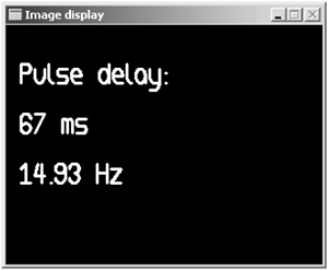
12.3.4. A shared memory access example
This section describes a slightly more complex example, eximg2, an image version of the user guide example ex2, which computes and displays the pulse frequency on the stream. The application graph (see Figure 12.23) is very similar to that of eximg1. They only differ by their image synthesis unit, which is now built around an instance of a cell type called myspace::MyCellImg2.
Figure 12.23. Conceptual graph for slightly more complex image manipulation example.

Computing a pulse frequency requires computing the time delay between two consecutive pulses. Some data must therefore be shared between the threads processing each pulse: the timestamp of the last pulse processed is saved in a node on the passive pulse. It serves as the reference time from which to compute the time delay when the next pulse is processed. The following code instantiates and connects the elements of the image synthesis unit for eximg2. Thanks to the modularity of SAI, this image synthesis unit directly replaces that of the previous example without any modification to the rest of the application graph.
//////////////////////////
// Image synthesis unit //
//////////////////////////

// create the source
fsf::CSource *pMySource=new fsf::CSource;
bSuccess &= (pMySource!=NULL);

// last time stamp
fsf::Int32Node *pLastTime =
  static_cast<fsf::Int32Node*>(scripting::CreateNode(
    std::string("FSF_INT32_NODE"),pMySource->GetPulse()));
bSuccess &= (pLastTime!=NULL);
if(bSuccess)
{
  // set name
  pLastTime->SetName(std::string("Last time"));
}

// cell
fsf::CCell *pMyCell =
  static_cast<fsf::CCell*>(scripting::CreateCell(
    std::string("MY_CELL_IMG2")));
bSuccess &= (pMyCell!=NULL);
if(bSuccess)
{
  // connect with source
  scripting::ConnectSource(pMyCell,pMySource);

  // connect with Pcell
  scripting::ConnectUpstreamCell(pMyCell,pPcell);
}
The myspace::MyCellImg2 cell type is in appearance quite similar to myspace::MyCellImg. Table 12.5 shows its logical definition.
| myspace::CMyCellImg2 (fsf::CCell) | MY CELL IMG2 |
|---|---|
| Active filter | [FSF_ACTIVE_PULSE "Root"] |
| Passive filter | [FSF_INT32_NODE "Last time"] |
| Output | (IMAGE_IMAGE "Image") |
The difference in the passive filter is reflected in the constructor code, as follows.
CMyCellImg2::CMyCellImg2()
: CCell()
{
  // default output name
  m_strOutputName.assign("Image");
  // set the filters
  m_pPassiveFilter =
    new fsf::CPassiveFilter<fsf::Int32Node>(
      std::string("Last time"));
  m_pActiveFilter =
    new fsf::CActiveFilter<fsf::CActivePulse>(
      std::string("Root"));
}
The overloaded process function encodes the specific behavior of the myspace::MyCellImg2 cell type.
void CMyCellImg2::Process(fsf::CPassiveHandle *pPassiveHandle,
                          fsf::CActiveHandle *pActiveHandle,
                          fsf::CActivePulse *pActivePulse)
{
First, a pointer to the target node in the passive pulse is retreived from the passive handle. In this case, it is a node of type fsf::Int32Node, which contains the value of the last timestamp read. Initialization of this value is handled in the reset case described below.
fsf::Int32Node *pLastTime =
  static_cast<fsf::Int32Node*>(pPassiveHandle->GetNode());
A pointer to the target node in the active pulse, in this case the root of the pulse, is also retrieved from the active handle.
fsf::CNode *pNode =
  static_cast<fsf::CNode*>(pActiveHandle->GetNode());
The first time this process function is executed, the passive node containing the last timestamp value must be set to the value of the timestamp of the current active pulse, and no significant time difference can be produced. This section is executed each time the m_bReset flag, data member of the fsf::CCell class, is set to true.
if(m_bReset)
{
  pLastTime->SetData(pNode->GetTime());
  m_bReset=false;
}
When the reset flag is not set, the regular processing is carried as follows.
else
{
First and foremost, the value of the last timestamp is collected from the passive node. The value in the node is updated immediately with the current timestamp value so that it is available as soon as possible for eventual parallel processes. In a strict parallel implementation, this read/write sequence should be placed in a critical section. In this simple example, the possible side effect is neglected. It can be made apparent by increasing the requested throughput until it becomes too high for the system on which the application is running. The throughput computed by this cell then becomes an integer fraction of the actual throughput because the reading and the updating sequence of the timestamp values is no longer in effect atomic.
DWORD dwLastTime=pLastTime->GetData();
pLastTime->SetData(static_cast<long>(pNode->GetTime()));
The remainder of the function code is quite similar to that of CMyCell Img::Process. The output image is created, and its data buffer is allocated and set to 0.
m_csOutputName.Lock();
image::CImage *pImage =
  new image::CImage(m_strOutputName,320,240,
                    3,image::IMAGE_DEPTH_8U,
                    pNode,fsf::g_pSystem->GetTime());
m_csOutputName.Unlock();

pImage->Allocate();
memset(pImage->Data(),0,pImage->Size());
A corresponding OpenCV header is created and linked to the image data buffer.
// Use OpenCV

CvSize size;
size.width=pImage->Width();
size.height=pImage->Height();

// Create IPL image header
IplImage *pIplImage =
  cvCreateImageHeader(size,IPL_DEPTH_8U,pImage->NbChannels());
// Link image data
pIplImage->imageData=pImage->Data();
pIplImage->origin=IPL_ORIGIN_BL;
Computed values are placed in a string, which is then written in the image buffer using the OpenCV cvPutText function.
CvFont font;
cvInitFont(&font,CV_FONT_VECTORO,0.8,0.8,0.0,2.0);

char str [255];
sprintf(str,"Pulse delay:");
cvPutText(pIplImage,str,cvPoint(15,200),&font,
          CV_RGB(255,255,255));

sprintf(str,"%d ms",pNode->GetTime()-dwLastTime);
cvPutText(pIplImage,str,cvPoint(15,150),&font,
          CV_RGB(255,255,255));

sprintf(str,"%.2f Hz", 1000. Of/ (pNode->GetTime()-dwLastTime));
cvPutText(pIplImage,str,cvPoint(15,100),&font,
          CV_RGB(255,255,255));
When all OpenCV-related operations are completed, the image header can be deleted.
cvReleaseImageHeader(&pIplImage);
Finally, the output image node is added to its parent's list of subnodes.
    pNode->AddComponent(pImage);
  }
}
The example implementation allows specification of the pulse rate on the command line (the default rate is 15 Hz). Figure 12.24 show a screen shot of the image display window.
Figure 12.24. Screen shot of the image display window for eximg2.