
This chapter covers the following subjects:
The oldest of the distance vector IP routing protocols still in widespread use, RIP currently exists in two versions. This chapter deals with version 1 of RIP. Chapter 6, “RIPv2, RIPng, and Classless Routing,” covers Version 2, which adds several enhancements to RIPv1. Most notably, RIPv1 is a classful routing protocol, whereas RIPv2 is classless. This chapter introduces classful routing, and Chapter 6 introduces classless routing. Chapter 6 also introduces RIPng, which is an adaptation of RIPv2 for support of IPv6.
Distance vector protocols, based on the algorithms developed by Bellman,[1] Ford, and Fulkerson,[2] were implemented beginning in 1969 in networks such as ARPANET and CYCLADES. In the mid-1970s Xerox developed a protocol called PARC[3] Universal Protocol, or PUP, to run on its 3-Mbps experimental predecessor to modern Ethernet. PUP was routed by the Gateway Information Protocol (GWINFO). PUP evolved into the Xerox Network Systems (XNS) protocol suite; concurrently, the Gateway Information Protocol became the XNS Routing Information Protocol. In turn, XNS RIP has become the precursor of such common routing protocols as Novell’s IPX RIP, AppleTalk’s Routing Table Maintenance Protocol (RTMP), and, of course, IP RIP.
The 4.2 Berkeley Software Distribution of UNIX, released in 1982, implemented RIP in a daemon called routed; many more recent versions of UNIX are based on the popular 4.2BSD and implement RIP in either routed or gated.[4] Oddly enough, a standard for RIP was not released until 1988, after the protocol was in extensive deployment. That was RFC 1058, written by Charles Hedrick, and it remains the only formal standard of RIPv1.
Depending on the literature you reads, RIP is either unjustly maligned or undeservedly popular. Although it lacks the capabilities of many of its successors, its simplicity and widespread use mean that compatibility problems between implementations are rare. RIP was designed for smaller networks in which the data links are fairly homogeneous. Within these constraints, and especially within many UNIX environments, RIP continues to be a popular routing protocol.
The RIP process operates from UDP port 520; all RIP messages are encapsulated in a UDP (User Datagram Protocol) segment with both the Source and Destination Port fields set to that value. RIP defines two message types: Request messages and Response messages. A Request message is used to ask neighboring routers to send an update. A Response message carries the update. The metric used by RIP is hop count, with 1 signifying a directly connected network of the advertising router and 16 signifying an unreachable network.
On startup, RIP broadcasts a packet carrying a Request message out each RIP-enabled interface. The RIP process then enters a loop, listening for RIP Request or Response messages from other routers. Neighbors receiving the Request send a Response containing their route table.
When the requesting router receives the Response messages, it processes the enclosed information. If a particular route entry included in the update is new, it is entered into the route table along with the address of the advertising router, which is read from the source address field of the update packet. If the route is for a network that RIP has already entered in the table, the existing entry will be replaced only if the new route has a lower hop count. If the advertised hop count is higher than the recorded hop count and the update was originated by the recorded next-hop router, the route will be marked as unreachable for a specified holddown period. If at the end of that time the same neighbor is still advertising the higher hop count, the new metric will be accepted.[5]
After startup, the router gratuitously sends a Response message out every RIP-enabled interface every 30 seconds, on average. The Response message, or update, contains the router’s full route table with the exception of entries suppressed by the split horizon rule. The update timer initiating this periodic update includes a random variable to prevent table synchronization.[6] As a result, the time between individual updates from a typical RIP process might be from 25 to 35 seconds. The specific random variable used by Cisco IOS, RIP_JITTER, subtracts up to 15 percent (4.5 seconds) from the update time. Therefore, updates from Cisco routers vary between 25.5 and 30 seconds (Figure 5-1). The destination address of the update is the all-hosts broadcast 255.255.255.255.[7]
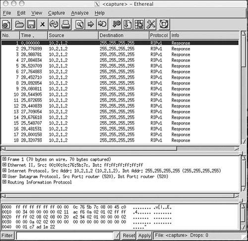
Figure 5-1. RIP adds a small random variable to the update timer at each reset to help avoid route table synchronization. The RIP updates from Cisco routers vary from 25.5 to 30 seconds, as shown in the delta times of these updates.
Several other timers are employed by RIP. Recall from Chapter 4 the invalidation timer, which distance vector protocols use to limit the amount of time a route can stay in a route table without being updated. RIP calls this timer the expiration timer, or timeout. The Cisco IOS calls it the invalid timer. The expiration timer is initialized to 180 seconds whenever a new route is established and is reset to the initial value whenever an update is heard for that route. If an update for a route is not heard within that 180 seconds (six update periods), the hop count for the route is changed to 16, marking the route as unreachable.
Another timer, the garbage collection or flush timer, is set to 240 seconds—60 seconds longer than the expiration time.[8] The route will be advertised with the unreachable metric until the garbage collection timer expires, at which time the route will be removed from the route table. Example 5-1 shows a route table in which a route has been marked as unreachable but has not yet been flushed.
Example 5-1. This router has not heard an update for subnet 10.3.0.0 for more than six update periods. The route has been marked unreachable but has not yet been flushed from the route table.
Mayberry#show ip route
Codes: C - connected, S - static, I - IGRP, R - RIP, M - mobile, B - BGP
       D - EIGRP, EX - EIGRP external, O - OSPF, IA - OSPF inter area
       E1 - OSPF external type 1, E2 - OSPF external type 2, E - EGP
       i - IS-IS, L1 - IS-IS level-1, L2 - IS-IS level-2, * - candidate default
Gateway of last resort is not set
     10.0.0.0 255.255.0.0 is subnetted, 4 subnets
C     10.2.0.0 is directly connected, Serial0
R     10.3.0.0 255.255.0.0 is possibly down,
        routing via 10.1.1.1, Ethernet0
C     10.1.0.0 is directly connected, Ethernet0
R     10.4.0.0 [120/1] via 10.2.2.2, 00:00:00, Serial0
Mayberry#
The third timer is the holddown timer, although RFC 1058 does not call for the use of holddowns. The Cisco implementation of RIP does use them. An update with a hop count higher than the metric recorded in the route table will cause the route to go into holddown for 180 seconds (again, six update periods).
These four timers can be manipulated with the command:
timers basic update invalid holddown flush
This command applies to the entire RIP process. If the timing of one router is changed, the timing of all the routers in the RIP domain must be changed. Therefore, these timers should not be changed from their default values without a specific, carefully considered reason.
RIP employs split horizon with poison reverse and triggered updates. A triggered update occurs whenever the metric for a route is changed and, unlike regularly scheduled updates, might include only the entry or entries that changed. Also unlike regular updates, a triggered update does not cause the receiving router to reset its update timer; if it did, a topology change could cause many routers to reset at the same time and thus cause the periodic updates to become synchronized. To avoid a “storm” of triggered updates after a topology change, another timer is employed. When a triggered update is transmitted, this timer is randomly set between one and five seconds; subsequent triggered updates cannot be sent until the timer expires.
Some hosts might employ RIP in a “silent” mode. These so-called silent hosts do not generate RIP updates, but listen for them and update their internal route tables accordingly. As an example, using routed with the -q option enables RIP in silent mode on a UNIX host.
The RIP message format is shown in Figure 5-2. Each message contains a command and a version number and can contain entries for up to 25 routes. Each route entry includes an address family identifier, the IP address reachable by the route, and the hop count for the route. If a router must send an update with more than 25 entries, multiple RIP messages must be produced. Note that the initial portion of the message is 4 octets, and each route entry is 20 octets. Therefore, the maximum message size is 4 + (25 × 20) = 504 octets. Including an eight-byte UDP header will make the maximum RIP datagram size (not including the IP header) 512 octets.
Command will always be set to either one, signifying a Request message, or two, signifying a Response message. There are other commands, but they are all either obsolete or reserved for private use.
Version will be set to one for RIPv1.
Address Family Identifier is set to two for IP. The only exception to this is a request for a router’s (or host’s) full route table, as discussed in the following section.
IP Address is the address of the destination of the route. This entry might be a major network address, a subnet, or a host route. The section titled “Classful Routing” examines how RIP distinguishes among these three types of entries.
Metric is, as previously mentioned, a hop count between 1 and 16.
An analyzer decode of a RIP message is shown in Figure 5-3.
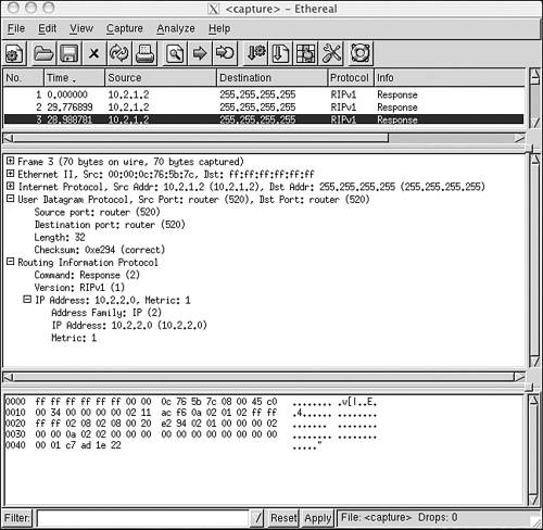
Figure 5-3. An Ethereal decode of a RIPv1 message shows the values in the message fields of this specific Response message.
Several historical influences contributed to the inelegant format of the RIP message in which far more bit spaces are unused than are used. These influences range from RIP’s original development as an XNS protocol, and the developer’s intentions for it to adapt to a large set of address families, to the influence of BSD, and its use of socket addresses, to the need for fields to fall on 32-bit word boundaries. Whatever the original motivations, you will see in Chapter 6 that these unused fields have since been put to good use.
A RIP Request message might request either a full route table or information on specific routes only. In the former case, the Request message will have a single route entry in which the address family identifier is set to zero, the address is all zeros (0.0.0.0), and the metric is 16. A device receiving such a request responds by unicasting its full route table to the requesting address, honoring such rules as split horizon and boundary summarization (discussed in “Classful Routing: Summarization at Boundary Routers,” later in this chapter).
Some diagnostic processes might need to know information about a specific route or routes. In this case, a Request message might be sent with entries specifying the addresses in question. A device receiving this request will process the entries one by one, building a Response message from the Request message. If the device has an entry in its route table corresponding to an address in the request, it will enter the metric of its own route entry into the metric field. If not, the metric field will be set to 16. The response will tell exactly what the router “knows,” with no consideration given to split horizon or boundary summarization.
As noted previously, hosts might run RIP in silent mode. This approach allows them to keep their route tables up to date by listening to RIP updates from routers without having to send RIP Response messages uselessly on the network. However, diagnostic processes might need to examine the route table of these silent hosts. Therefore, RFC 1058 specifies that if a silent host receives a request from a UDP port other than the standard RIP port of 520, the host must send a response.
The route table in Example 5-2 contains RIP-derived routes, which are recognized from the key to the left of each entry. Of significance in these entries are the bracketed tuples; as discussed in Chapter 3, “Static Routing,” the first number is the administrative distance, and the second number is the metric. It is readily seen that RIP has an administrative distance of 120, and as already stated, the metric for RIP is hop count. Therefore, network 10.8.0.0 is two hops away, via either E0 or S1. If more than one route exists to the same destination with equal hop counts, equal-cost load balancing will be performed. The route table of Example 5-2 contains several multiple, equal-cost routes.
Example 5-2. This route table contains subnets of networks 10.0.0.0 and 172.25.0.0. All networks not directly connected were derived by RIP.
MtPilate#show ip route
Codes: C - connected, S - static, I - IGRP, R - RIP, M - mobile, B - BGP
       D - EIGRP, EX - EIGRP external, O - OSPF, IA - OSPF inter area
       E1 - OSPF external type 1, E2 - OSPF external type 2, E - EGP
       i - IS-IS, L1 - IS-IS level-1, L2 - IS-IS level-2, * - candidate default
Gateway of last resort is not set
    10.0.0.0 255.255.0.0 is subnetted, 9 subnets
R    10.10.0.0 [120/3] via 10.5.5.1, 00:00:20, Serial1
               [120/3] via 10.1.1.1, 00:00:21, Ethernet0
R    10.11.0.0 [120/3] via 10.5.5.1, 00:00:21, Serial1
               [120/3] via 10.1.1.1, 00:00:21, Ethernet0
R    10.8.0.0 [120/2] via 10.1.1.1, 00:00:21, Ethernet0
              [120/2] via 10.5.5.1, 00:00:21, Serial1
R    10.9.0.0 [120/2] via 10.5.5.1, 00:00:21, Serial1
              [120/2] via 10.1.1.1, 00:00:21, Ethernet0
R    10.3.0.0 [120/1] via 10.1.1.1, 00:00:21, Ethernet0
              [120/1] via 10.5.5.1, 00:00:21, Serial1
C    10.1.0.0 is directly connected, Ethernet0
R    10.6.0.0 [120/1] via 10.1.1.1, 00:00:21, Ethernet0
              [120/1] via 10.5.5.1, 00:00:22, Serial1
R    10.7.0.0 [120/2] via 10.1.1.1, 00:00:22, Ethernet0
              [120/2] via 10.5.5.1, 00:00:22, Serial1
C    10.5.0.0 is directly connected, Serial1
   172.25.0.0 255.255.255.0 is subnetted, 3 subnets
R    172.25.153.0 [120/1] via 172.25.15.2, 00:00:03, Serial0
R    172.25.131.0 [120/1] via 172.25.15.2, 00:00:03, Serial0
C    172.25.15.0 is directly connected, Serial0
When a packet enters a RIP-speaking router and a route table lookup is performed, the various choices in the table are pruned until a single path remains. First, the network portion of the destination address is read and the route table is consulted for a match. It is this first step of reading the major class A, B, or C network number that defines a classful route table lookup. If there is no match for the major network, the packet is dropped and an ICMP Destination Unreachable message is sent to the packet’s source. If there is a match for the network portion, the subnets listed for that network are examined. If a match can be found, the packet is routed. If a match cannot be made, the packet is dropped and a Destination Unreachable message is sent.
Classful route lookups can be illustrated with three examples (referring to Example 5-2):
If a packet with a destination address of 192.168.35.3 enters this router, no match for network 192.168.35.0 is found in the route table, and the packet is dropped.
If a packet with a destination address of 172.25.33.89 enters the router, a match is made to class B network 172.25.0.0/24. The subnets listed for this network are then examined; no match can be made for subnet 172.25.33.0, so that packet, too, is dropped.
Finally, a packet destined for 172.25.153.220 enters the router. This time 172.25.0.0/24 is matched, then subnet 172.25.153.0 is matched, and the packet is forwarded to next-hop address 172.25.15.2.
Another look at Figure 5-2 reveals that there is no provision for RIP to advertise a subnet mask along with each route entry. And accordingly, no masks are associated with the individual subnets in the route table. Therefore, if the router whose forwarding database is depicted in Example 5-2 receives a packet with a destination address of 172.25.131.23, there is no positive way to determine where the subnet bits end and the host bits begin, or even if the address is subnetted at all.
The router’s only recourse is to assume that the mask configured on one of its interfaces attached to 172.25.0.0 is used consistently throughout the network. It will use its own mask for 172.25.0.0 to derive the subnet of the destination address. As the route tables throughout this chapter illustrate, a router that is directly connected to a network will list the network in a heading along with the subnet mask of the connecting interface and will then list all the known subnets of the network. If the network is not directly connected, there is a listing only for the major-class network and no associated mask.
Because the destination addresses of packets being routed by a classful routing protocol are interpreted according to the subnet masks locally configured on the router’s interfaces, all subnet masks within a major, class-level network must be consistent.
A question arises from the preceding discussion: How does a RIP process interpret the subnet of a major network if it has no interfaces attached to that network? Without an interface on the class A, B, or C network of the destination, the router has no way of recognizing the correct subnet mask to use and therefore no way of correctly identifying the subnet.
The solution is simple: If a router has no direct attachments to the network, it needs only a single route entry pointing toward a router that is directly attached.
Figure 5-4 shows a router that is attached at the boundary of two major networks, the class A network 10.0.0.0 and the class C network 192.168.115.0. This boundary router does not send details of the subnets of one major network into the other major network. As the illustration shows, it automatically performs summarization, or subnet hiding. It advertises only the address 10.0.0.0 into network 192.168.115.0 and advertises only the address.
Figure 5-4. This router, at the boundary of two major networks, does not advertise the subnets of one network to routers within the other network.
In this way, the route tables for routers within network 192.168.115.0 have only a single entry that directs packets for 10.0.0.0 toward the boundary router. The boundary router has an interface directly on network 10.0.0.0 and, therefore, has a subnet mask with which to derive the subnet for routing a packet within that network’s “cloud.” Example 5-3 shows what the route table of a router within 192.168.115.0 would look like with a single, subnetless entry for 10.0.0.0.
Example 5-3. This router has a single entry pointing toward network 10.0.0.0. The next-hop address is the boundary router, because the network is recorded as being one hop away.
Raleigh#show ip route
Codes: C - connected, S - static, I - IGRP, R - RIP, M - mobile, B - BGP
       D - EIGRP, EX - EIGRP external, O - OSPF, IA - OSPF inter area
       E1 - OSPF external type 1, E2 - OSPF external type 2, E - EGP
       i - IS-IS, L1 - IS-IS level-1, L2 - IS-IS level-2, * - candidate default
Gateway of last resort is not set
R    10.0.0.0 [120/1] via 192.168.115.40, 00:00:10, Ethernet1
     192.168.115.0 255.255.255.240 is subnetted, 6 subnets
C       192.168.115.32 is directly connected, Ethernet1
R       192.168.115.64 [120/1] via 192.168.115.99, 00:00:13, Ethernet0
C       192.168.115.96 is directly connected, Ethernet0
C       192.168.115.128 is directly connected, Serial0
R       192.168.115.192 [120/1] via 192.168.115.99, 00:00:13, Ethernet0
R       192.168.115.224 [120/1] via 192.168.115.130, 00:00:25, Serial0
Raleigh#
Chapter 3’s brief discussion of discontiguous subnets—subnets of a major network address separated by a different major network—notes that they present a problem for classful routing protocols such as RIP and IGRP. The problem occurs when discontiguous subnets are automatically summarized at network boundaries. A case study in the configuration section of this chapter demonstrates the problem and a solution.
The defining characteristic of a classful routing protocol is that it does not advertise an address mask along with the advertised destination address. Therefore, a classful routing protocol must first match the major class A, B, or C network portion of a destination address. For every packet passing through the router
If the destination address is a member of a directly connected major network, the subnet mask configured on the interface attached to that network will be used to determine the subnet of the destination address. Therefore, the same subnet mask must be used consistently throughout that major network.
If the destination address is not a member of a directly connected major network, the router will try to match only the major class A, B, or C portion of the destination address.
In keeping with the simple nature of RIP, configuration is an easy task. There is one command to enable the RIP process and one command for each network on which RIP is to run. Beyond that, RIP has few configuration options.
Only two steps are necessary to configure RIP:
Enable RIP with the command router rip.
Specify each major network on which to run RIP with the network command. Figure 5-5 shows a four-router network, with four major network numbers. Router Goober is attached to two subnets of network 172.17.0.0.

The commands necessary to enable RIP are displayed in Example 5-4.
Similarly, Opie has two subnets of the same network and will configure with the commands in Example 5-5.
Executing any router command puts the router into config-router mode, indicated in the prompt. The classful nature of RIP and the subnet hiding at network boundaries mean that no subnets can be specified with the network command—only major class A, B, or C network addresses. RIP can run on any interface configured with any address belonging to the network specified with the network command.
Barney is attached to two networks—10.0.0.0 and 192.168.83.0. Therefore, both networks must be specified as in Example 5-6.
Andy has one attachment to network 192.168.83.0, attachments to two subnets of 192.168.12.0, and attachments to two subnets of 172.17.0.0. Example 5-7 shows its configuration.
Example 5-7. Andy’s RIP configuration.
router rip network 172.17.0.0 network 192.168.12.0 network 192.168.83.0
In Example 5-8, the command debug ip rip has been turned on in Andy. Of particular interest here is the subnet hiding that the router is performing. The subnets 192.168.12.64 and 192.168.12.192 are advertised between interfaces E0 and E2, which are both attached to network 192.168.12.0, but the network is summarized out E1, S0, and S1, which are all attached to different networks. Likewise, networks 192.168.83.0 and 172.17.0.0 are being summarized across classful boundaries. Notice also that Andy is receiving a summary route for network 10.0.0.0 from Barney. Finally, split horizon can be observed here. For example, the advertisement to Barney out E1 contains no entries for 10.0.0.0 or 192.168.83.0.
Example 5-8. These debug messages show the RIP updates received and sent by Router Andy. The results of both network summarization and split horizon can be observed in the update entries.
Andy#debug ip rip
RIP protocol debugging is on
Andy#
RIP: sending v1 update to 255.255.255.255 via Ethernet0 (192.168.12.65)
RIP: build update entries
     subnet 192.168.12.192, metric 1
     network 10.0.0.0, metric 2
     network 192.168.83.0, metric 1
     network 172.17.0.0, metric 1
RIP: sending v1 update to 255.255.255.255 via Ethernet1 (192.168.83.1)
RIP: build update entries
     network 192.168.12.0, metric 1
     network 172.17.0.0, metric 1
RIP: sending v1 update to 255.255.255.255 via Ethernet2 (192.168.12.195)
RIP: build update entries
     subnet 192.168.12.64, metric 1
     network 10.0.0.0, metric 2
     network 192.168.83.0, metric 1
     network 172.17.0.0, metric 1
RIP: sending v1 update to 255.255.255.255 via Serial0 (172.17.1.1)
RIP: build update entries
     subnet 172.17.4.0, metric 2
     subnet 172.17.2.0, metric 1
     network 10.0.0.0, metric 2
     network 192.168.83.0, metric 1
     network 192.168.12.0, metric 1
RIP: sending v1 update to 255.255.255.255 via Serial1 (172.17.2.1)
RIP: build update entries
     subnet 172.17.1.0, metric 1
     subnet 172.17.3.0, metric 2
     network 10.0.0.0, metric 2
     network 192.168.83.0, metric 1
     network 192.168.12.0, metric 1
RIP: received v1 update from 172.17.1.2 on Serial0
     172.17.3.0 in 1 hops
RIP: received v1 update from 192.168.83.244 on Ethernet1
     10.0.0.0 in 1 hops
RIP: received v1 update from 172.17.2.2 on Serial1
172.17.4.0 in 1 hopsThe Router Floyd has been added to the network (Figure 5-6).
It is desired that no RIP advertisements be exchanged between Floyd and Andy. This is easy enough at Floyd, as displayed in Example 5-9.
By not including a network statement for 192.168.12.0, Floyd will not advertise on interface 192.168.12.66. Andy, however, has two interfaces attached to 192.168.12.0; the network must be included under RIP. To block RIP broadcasts on an interface connected to a subnet of a RIP-enabled network, add the passive-interface command to the RIP process. Andy’s RIP configuration is displayed in Example 5-10.
Example 5-10. Andy’s RIP configuration with a passive interface.
router rip
 passive-interface Ethernet0
 network 172.17.0.0
 network 192.168.12.0
 network 192.168.83.0
passive-interface is not a RIP-specific command; it might be configured under any IP routing protocol. Using the passive-interface command essentially makes a router a silent host on the data link specified. Like other silent hosts, it still listens to RIP broadcasts on the link and updates its route table accordingly. If the desired result is to prevent the router from learning routes on the link, it must be achieved by more intricate control of routing updates, namely by filtering out updates. (Route filters are discussed in Chapter 13, “Route Filtering.”) Unlike a silent host, the router does not respond to a RIP Request received on a passive interface.
Next, Router Bea is added to the Ethernet link that Andy and Floyd share (Figure 5-7). The no-RIP policy between Andy and Floyd remains in place, but now Bea and Andy, like Bea and Floyd, must exchange RIP advertisements.
Figure 5-7. No RIP updates should be exchanged between Andy and Floyd, but both should exchange updates with Bea.
The configuration of Bea is straightforward (see Example 5-11).
The addition of a neighbor command under the RIP processes of Andy enables RIP to send a unicast advertisement to Bea’s interface while the passive-interface command continues to prevent broadcast updates on the link.[9]
Andy’s configuration is displayed in Example 5-12.
Example 5-12. Andy’s RIP configuration includes a passive interface with a neighbor statement to enable unicast updates.
router rip
 passive-interface Ethernet0
 network 172.17.0.0
 network 192.168.12.0
 network 192.168.83.0
 neighbor 192.168.12.67
Because Floyd must now send advertisements to Bea, a network command for 192.168.12.0 must be added. passive-interface is also added to prevent broadcast updates, and a neighbor command is added to enable unicast updates to Bea (see Example 5-13).
Example 5-13. Floyd’s RIP configuration with unicast updates to neighbor 192.168.12.67.
router rip
passive-interface Ethernet0
network 192.168.12.0
network 192.168.100.0
neighbor 192.168.12.67
By enabling debug ip rip events at Andy, the results of the new configuration can be verified (Example 5-14). Andy is receiving updates from Bea, but not from Floyd, and is sending updates directly to Bea’s interface but is not broadcasting on its E0.
Example 5-14. The only updates Andy is sending out interface E0 are unicasts to Bea. Updates are being received from Bea but not from Floyd.
Andy#debug ip rip events
RIP event debugging is on
Andy#
RIP: received v1 update from 192.168.12.67 on Ethernet0
RIP: Update contains 1 routes
RIP: sending v1 update to 255.255.255.255 via Ethernet1 (192.168.83.1)
RIP: Update contains 4 routes
RIP: Update queued
RIP: Update sent via Ethernet1
RIP: sending v1 update to 255.255.255.255 via Ethernet2 (192.168.12.195)
RIP: Update contains 6 routes
RIP: Update queued
RIP: Update sent via Ethernet2
RIP: sending v1 update to 255.255.255.255 via Serial0 (172.17.1.1)
RIP: Update contains 7 routes
RIP: Update queued
RIP: Update sent via Serial0
RIP: sending v1 update to 255.255.255.255 via Serial1 (172.17.2.1)
RIP: Update contains 7 routes
RIP: Update queued
RIP: Update sent via Serial1
RIP: sending v1 update to 192.168.12.67 via Ethernet0 (192.168.12.65)
RIP: Update contains 4 routes
RIP: Update queued
RIP: Update sent via Ethernet0
RIP: received v1 update from 172.17.1.2 on Serial0
RIP: Update contains 1 routes
RIP: received v1 update from 172.17.2.2 on Serial1
RIP: Update contains 1 routes
RIP: received v1 update from 192.168.12.67 on Ethernet0
RIP: Update contains 1 routes
Although Bea has learned routes from both Andy and from Floyd, and is broadcasting updates on the shared Ethernet, the policy still works because split horizon prevents Bea from advertising the routes learned from those two routers back onto the Ethernet.
In Figure 5-8, another router has been added to the network with a subnet 10.33.32.0/20 on its E1 interface. The problem is that the other subnet of network 10.0.0.0, 10.33.0.0/20, is connected to Barney, and the only route between the subnets is via 192.168.83.0 and 192.168.12.0—two entirely different networks. As a result, network 10.0.0.0 is discontiguous.
Figure 5-8. Classful protocols such as RIP and IGRP cannot route a topology in which the subnets of network 10.0.0.0 are separated by different networks.
Barney will consider itself a border router between network 10.0.0.0 and network 192.168.83.0; likewise, Ernest_T will consider itself a border router between 10.0.0.0 and 192.168.12.0. Both will advertise a summary route of 10.0.0.0, and as a result Andy will be “fooled into thinking” that it has two equal-cost paths to the same network. Andy will load share on the links to Barney and Ernest_T, and there is now only a 50-50 chance that packets to network 10.0.0.0 will reach the correct subnet.
The solution is to configure subnets of network 10.0.0.0 on the same links on which 192.168.83.0/24 and 192.168.12.192/27 reside. This is accomplished with secondary IP addresses, as displayed in Example 5-15, Example 5-16, and Example 5-17.
Example 5-15. Barney is configured with secondary IP addresses.
interface e0
 ip address 10.33.55.1 255.255.240.0 secondary
Example 5-16. Andy is configured with secondary IP addresses, and a new network is added to RIP.
interface e1
 ip address 10.33.55.2 255.255.240.0 secondary
interface e2
 ip address 10.33.75.1 255.255.240.0 secondary
router rip
 network 10.0.0.0
Example 5-17. Ernest_T is configured with secondary IP addresses.
interface e0
 ip address 10.33.75.2 255.255.240.0 secondary
Because Andy did not previously have an interface on network 10.0.0.0, a network statement is added to the RIP process. The result of the configuration is shown in Figure 5-9. The existing logical network structure remains in place, and a contiguous network 10.0.0.0 is “overlaid” onto it.
Figure 5-9. Secondary addresses are used to connect the subnets of network 10.0.0.0 across the same links on which other network addresses exist.
Example 5-18 shows Ernest_T’s route table. Of interest here are the dual, equal-cost routes associated with next-hop addresses 10.33.75.1 and 192.168.12.195.
Example 5-18. The routing process in this router sees the subnets 192.168.12.192/27 and 10.33.64.0/20 as separate links, although they reside on the same physical interface.
Ernest_T#show ip route
Codes: C - connected, S - static, I - IGRP, R - RIP, M - mobile, B - BGP
       D - EIGRP, EX - EIGRP external, O - OSPF, IA - OSPF inter area
       E1 - OSPF external type 1, E2 - OSPF external type 2, E - EGP
       i - IS-IS, L1 - IS-IS level-1, L2 - IS-IS level-2, * - candidate default
Gateway of last resort is not set
    10.0.0.0 255.255.240.0 is subnetted, 4 subnets
C     10.33.32.0 is directly connected, Ethernet1
R     10.33.48.0 [120/1] via 10.33.75.1, 00:00:05, Ethernet0
R     10.33.0.0 [120/2] via 10.33.75.1, 00:00:05, Ethernet0
C     10.33.64.0 is directly connected, Ethernet0
R     192.168.83.0 [120/1] via 192.168.12.195, 00:00:05, Ethernet0
                   [120/1] via 10.33.75.1, 00:00:05, Ethernet0
      192.168.12.0 255.255.255.224 is subnetted, 2 subnets
R     192.168.12.64 [120/1] via 192.168.12.195, 00:00:05, Ethernet0
C     192.168.12.192 is directly connected, Ethernet0
R     192.168.200.0 [120/2] via 192.168.12.195, 00:00:05, Ethernet0
                    [120/2] via 10.33.75.1, 00:00:05, Ethernet0
R     172.17.0.0 [120/1] via 192.168.12.195, 00:00:06, Ethernet0
                 [120/1] via 10.33.75.1, 00:00:06, Ethernet0
Ernest_T#
Because the routing process sees secondary addresses as separate data links, caution should be used when planning them on RIP or IGRP networks. A separate RIP update will be broadcast on each subnet; if the updates are large and the bandwidth of the physical link is limited (such as on serial links), the multiple updates can cause congestion. Multiple updates on a link configured with secondary addresses can be observed in Example 5-21, later in this chapter.
Type cautiously when entering secondary addresses. If you omit the keyword secondary, the router will assume that the primary address is to be replaced with the new address. Making this mistake on an in-service interface will have serious consequences.
A serial link, to be used as a backup, has been added between Ernest_T and Barney (Figure 5-10). This link should be used only if the route via Andy fails. The problem is that the path between Barney’s 10.33.0.0 subnet and Ernest_T’s 10.33.32.0 subnet is one hop via the serial link and two hops via the preferred Ethernet links. Under normal circumstances, RIP will choose the serial link.
Figure 5-10. RIP metrics must be manipulated so that the two-hop Ethernet route between Barney and Ernest_T will be preferred over the one-hop serial route.
The route metrics can be manipulated with the offset-list command. The command specifies a number to add to the metric of a route entry and references an access list[10] to determine which route entries to modify. The syntax of the command is as follows:
offset-list {access-list-number | name} { in | out} offset [type number]
The configuration of Ernest_T is in Example 5-19.
Example 5-19. Ernest_T’s RIP configuration with an inbound offset list.
access-list 1 permit 10.33.0.0 0.0.0.0
router rip
 network 192.168.12.0
 network 10.0.0.0
 offset-list 1 in 2 Serial0
An access list is written that identifies the route to subnet 10.33.0.0. The syntax of the offset list says, “Examine RIP advertisements incoming from interface S0. For route entries matching the addresses specified in access list 1, add 2 hops to the metric.”
After Barney is configured, it will have the entries in Example 5-20 in its configuration file.
Example 5-20. Barney’s RIP configuration with an inbound offset list.
router rip
 offset-list 5 in 2 Serial0
 network 10.0.0.0
 network 192.168.83.0
!
access-list 5 permit 10.33.32.0 0.0.0.0
Example 5-21 shows the results of the configuration at Ernest_T.
Example 5-21. The addition of the hops specified in the offset list changes the hop count to subnet 10.33.0.0/20 via S0 from one to three. Now the two-hop route via E0 is used.
Ernest_T#debug ip rip
RIP protocol debugging is on
Ernest_T#
RIP: received v1 update from 192.168.12.195 on Ethernet0
     192.168.12.64 in 1 hops
     10.0.0.0 in 1 hops
     192.168.83.0 in 1 hops
     192.168.200.0 in 2 hops
     172.17.0.0 in 1 hops
RIP: received v1 update from 10.33.75.1 on Ethernet0
     10.33.48.0 in 1 hops
     10.33.0.0 in 2 hops
     192.168.83.0 in 1 hops
     192.168.12.0 in 1 hops
     192.168.200.0 in 2 hops
     172.17.0.0 in 1 hops
RIP: received v1 update from 10.33.25.1 on Serial0
     10.33.32.0 in 3 hops
     10.33.48.0 in 1 hops
     10.33.0.0 in 3 hops
     192.168.83.0 in 1 hops
     192.168.200.0 in 3 hops
     172.17.0.0 in 2 hops
RIP: sending v1 update to 255.255.255.255 via Ethernet0 (192.168.12.196)
RIP: build update entries
     network 10.0.0.0, metric 1
RIP: sending v1 update to 255.255.255.255 via Ethernet0 (10.33.75.2)
RIP: build update entries
     subnet 10.33.32.0, metric 1
     subnet 10.33.16.0, metric 1
RIP: sending v1 update to 255.255.255.255 via Ethernet1 (10.33.35.1)
RIP: build update entries
     subnet 10.33.48.0, metric 2
     subnet 10.33.0.0, metric 3
     subnet 10.33.16.0, metric 1
     subnet 10.33.64.0, metric 1
     network 192.168.83.0, metric 2
     network 192.168.12.0, metric 1
     network 192.168.200.0, metric 3
     network 172.17.0.0, metric 2
RIP: sending v1 update to 255.255.255.255 via Serial0 (10.33.25.2)
RIP: build update entries
     subnet 10.33.32.0, metric 3
     subnet 10.33.0.0, metric 3
     subnet 10.33.64.0, metric 1
     network 192.168.12.0, metric 1
     network 192.168.200.0, metric 3
     network 172.17.0.0, metric 2
Alternatively, instead of having the two routers modify incoming routes, the routers can be configured to modify their outgoing routes. The configurations in Example 5-22 and Example 5-23 will have the same effects as the previous configurations.
Example 5-22. Ernest_T’s RIP configuration uses outbound offset lists.
router rip
 offset-list 3 out 2 Serial0
 network 192.168.12.0
 network 10.0.0.0
!
access-list 3 permit 10.33.32.0 0.0.0.0
Example 5-23. Barney’s RIP configuration uses outbound offset lists.
router rip
 offset-list 7 out 2 Serial0
 network 10.0.0.0
 network 192.168.83.0
!
access-list 7 permit 10.33.0.0 0.0.0.0
Several other options are available for configuring offset lists. If no interface is identified, the list will modify all incoming or outgoing updates specified by the access list on any interface. If no access list is called (by using a zero as the access list number), the offset list will modify all incoming or outgoing updates.
Caution should be applied when choosing whether to use offset lists on incoming or outgoing advertisements. If more than two routers are attached to a broadcast network, consideration must be given to whether a single router should broadcast a modified advertisement to all its neighbors or whether a single router should modify a received advertisement.
Care must also be exercised when implementing offset lists on routes that are in use. When an offset list causes a next-hop router to advertise a higher metric than it had been advertising, the route will be marked unreachable until the holddown timer expires.
There are times when you will want to minimize network traffic caused by routing updates. Regular RIP updates, by default, occur every 30 seconds and include the full route table, in addition to the flash updates that are transmitted when there is a change in the metric of route entries. In a network with many subnets, routing updates can affect traffic, especially on low bandwidth links. You also might want to minimize routing updates if you are paying for traffic traversing a link.
Suppose utilization on the new serial link from Barney to Ernest_T, in Figure 5-10, is high. The RIP routing traffic can be reduced in two ways to minimize the traffic caused by the routing protocol: The timers can be adjusted so the updates don’t occur as frequently, but this will cause longer convergence time when the primary link fails. Or triggered extensions can be configured to eliminate periodic RIP updates.
The interface command ip rip triggered enables the triggered extensions of RIP.[11] After two routers on a serial link determine both are configured for triggered RIP, route table updates are minimized to include only the initial exchange of route tables and updates when changes to the route tables occur. This command is only available on serial links and must be configured on both ends of the link before taking affect.
The triggered extensions are configured on Barney’s serial link to Ernest_T with the configuration in Example 5-24.
Example 5-24. Barney is configured with triggered, rather then periodic, updates.
interface serial 0
 ip rip triggered
Debugging on Barney shows that Barney attempts to establish a triggered relationship with the router on the other end of the link. Barney sends polls and waits for acknowledgments. When it doesn’t receive any acknowledgments, Barney begins sending regular RIPv1 updates. Output from debug ip rip and debug ip rip trigger is shown in Example 5-25.
Example 5-25. When a router is initially configured with triggered RIP, it polls to determine if its neighbor is also configured for triggered RIP.
Barney#debug ip rip
RIP protocol debugging is
Barney#debug ip rip trigger
RIP trigger debugging is on

Barney(config)#interface serial 0
Barney(config-if)#ip rip triggered
* 13:22:10.223: RIP: sending triggered request on Serial0 to 255.255.255.255
* 13:22:10.223: RIP: Start poll timer from 10.33.25.1 on Serial0
* 13:22:15.223: RIP-TIMER: polling timer on Serial0(10.33.25.1) expired
* 13:22:15.223: RIP: sending triggered request on Serial0 to 255.255.255.255
* 13:22:15.223: RIP: Start poll timer from source 10.33.25.1 on Serial0
* 13:22:16.733: RIP: received v1 update from 10.33.25.2 on Serial0
* 13:22:16.733:      172.17.8.0 in 1 hops
* 13:22:16.733:      172.17.9.0 in 1 hops
* 13:22:16.737:      172.17.10.0 in 1 hops
* 13:22:16.737:      172.17.11.0 in 1 hops
* 13:22:19.466: RIP-TIMER: sending timer on Serial0 expired
* 13:22:20.223: RIP-TIMER: polling timer on Serial0(10.33.25.1) expired
* 13:22:20.223: RIP: sending triggered request on Serial0 to 255.255.255.255
* 13:22:20.223: RIP: Start poll timer from source 10.33.25.1 on Serial0
* 13:22:25.223: RIP-TIMER: polling timer on Serial0(10.33.25.1) expired
* 13:22:25.223: RIP: sending triggered request on Serial0 to 255.255.255.255
* 13:22:25.223: RIP: Start poll timer from source 10.33.25.1 on Serial0
* 13:22:30.224: RIP-TIMER: polling timer on Serial0(10.33.25.1) expired
* 13:22:30.224: RIP: sending triggered request on Serial0 to 255.255.255.255
* 13:22:30.224: RIP: Start poll timer from source 10.33.25.1 on Serial0
* 13:22:35.224: RIP-TIMER: polling timer on Serial0(10.33.25.1) expired
* 13:22:35.224: RIP: sending triggered request on Serial0 to 255.255.255.255
* 13:22:35.224: RIP: Start poll timer from source 10.33.25.1 on Serial0
* 13:22:40.224: RIP-TIMER: polling timer on Serial0(10.33.25.1) expired
* 13:22:40.224: RIP: Poll 6 times on Serial0 thru 10.33.25.1 without any ack
* 13:22:46.126: RIP: received v1 update from 10.33.25.2 on Serial0
* 13:22:46.126:      172.17.8.0 in 1 hops
* 13:22:46.126:      172.17.9.0 in 1 hops
* 13:22:46.130:      172.17.10.0 in 1 hops
* 13:22:46.130:      172.17.11.0 in 1 hops
* 13:22:49.054: RIP-TIMER: sending timer on Serial0 expired
* 13:22:49.054: RIP: sending v1 update to 255.255.255.255 via Serial0(10.33.25.1)
* 13:22:49.054: RIP: build update entries
* 13:22:49.054:   network 10.0.0.0 metric 2
* 13:22:49.054:   subnet 172.17.0.0 metric 2
* 13:22:49.054:   subnet 172.17.2.0 metric 1
* 13:22:49.058:   subnet 172.17.4.0 metric 2
* 13:22:49.058:   network 192.168.12.0 metric 1
* 13:22:49.058:   network 192.168.83.0 metric 1
* 13:23:13.070: RIP: received v1 update from 10.33.25.2 on Serial0
* 13:23:13.070:      172.17.8.0 in 1 hops
* 13:23:13.074:      172.17.9.0 in 1 hops
* 13:23:13.074:      172.17.10.0 in 1 hops
* 13:23:13.074:      172.17.11.0 in 1 hops
* 13:23:17.385: RIP-TIMER: sending timer on Serial0 expired
* 13:23:17.385: RIP: sending v1 update to 255.255.255.255 via Serial0(10.33.25.1)
* 13:23:17.385: RIP: build update entries
* 13:23:17.385:   network 10.0.0.0 metric 2
* 13:23:17.385:   subnet 172.17.0.0 metric 2
* 13:23:17.385:   subnet 172.17.2.0 metric 1
* 13:23:17.389:   subnet 172.17.4.0 metric 2
* 13:23:17.389:   network 192.168.12.0 metric 1
* 13:23:17.389:   network 192.168.83.0 metric 1
The debug output shows that the configured router sends six triggered requests. For each one, the router sets a poll timer, which expires in five seconds. If no acknowledgment is received within the five seconds, another triggered request is sent. If no acknowledgment is received after six triggered requests have been sent and the polls have expired, the router waits for the next regular update time and broadcasts a RIP update. While Barney is sending triggered requests, Ernest_T continues to broadcast its own RIP updates, which Barney processes.
Now, Ernest_T’s serial link to Barney is configured with triggered RIP. Through debugging on Ernest_T, Example 5-26 shows the initialization process between Barney and Ernest_T.
Example 5-26. Debug output shows two routers establishing a triggered RIP relationship.
* 13:35:04.612: RIP: received v1 triggered request from 172.17.1.2 on Serial0
* 13:35:04.616: RIP: Trigger rip running on network 172.17.0.0 thru Serial0
* 13:35:04.616: RIP: 172.17.1.2 change state from DOWN to INIT
* 13:35:04.616: RIP: 172.17.1.2 change state from INIT to LOADING
* 13:35:04.616: RIP: send v1 triggered flush update to 172.17.1.2 on Serial0
* 13:35:04.616: RIP: assigned sequence number 25 on Serial0
* 13:35:04.616: RIP: build update entries
* 13:35:04.620:   route 202: network 192.168.12.0 metric 1
* 13:35:04.620:   route 206: subnet 172.17.2.0 metric 1
* 13:35:04.620:   route 208: network 192.168.83.0 metric 1
* 13:35:04.620:   route 210: network 10.0.0.0 metric 2
* 13:35:04.620:   route 215: subnet 172.17.4.0 metric 2
* 13:35:04.620:   route 217: subnet 172.17.0.0 metric 2
* 13:35:04.624: RIP: Update contains 6 routes, start 202, end 226
* 13:35:04.624: RIP: start retransmit timer of 172.17.1.2
* 13:35:04.680: RIP: received v1 triggered ack from 172.17.1.2 on Serial0 flush seq# 25
* 13:35:04.684: RIP: 172.17.1.2 change state from LOADING to FULL
* 13:35:04.688: RIP: received v1 triggered update from 172.17.1.2 on Serial0
* 13:35:04.688: RIP: sending v1 ack to 172.17.1.2 via Serial0 (172.17.1.1), flush,
seq# 14
* 13:35:04.736: RIP: received v1 triggered update from 172.17.1.2 on Serial0
* 13:35:04.740: RIP: sending v1 ack to 172.17.1.2 via Serial0 (172.17.1.1), seq# 15
* 13:35:04.740:      172.17.9.0 in 1 hops
* 13:35:04.740:      172.17.8.0 in 1 hops
* 13:35:04.740:      172.17.11.0 in 1 hops
* 13:35:04.744:      172.17.10.0 in 1 hops
* 13:35:52.879: RIP-TIMER: sending timer on Serial0 expired
* 13:36:21.907: RIP-TIMER: sending timer on Serial0 expired
* 13:36:47.421: RIP-TIMER: sending timer on Serial0 expired
The triggered state goes from DOWN, through INIT and LOADING, to FULL. Route information is exchanged and updates are acknowledged. At the end of the output, you can see that the RIP update timers are expiring, but no new updates are sent, nor are updates received.
Troubleshooting RIP is relatively simple. Most difficulties with classful protocols such as RIP involve either misconfigured subnet masks or discontiguous subnets. If a route table contains inaccurate or missing routes, check all subnets for contiguity and all subnet masks for consistency.
A final command can be useful when a high-speed router is sending multiple RIP messages to a low-speed router. In such a case, the low-speed router might not be able to process updates as quickly as they are received, and routing information might be lost. output-delay delay can be used under the RIP command to set an interpacket gap of between 8 and 50 milliseconds. (The default is 0 milliseconds.)
The simplicity, maturity, and widespread acceptance of RIP ensure that it will be in service for many years to come. However, you saw in this chapter the limitations of its classful nature. The next chapter continues to examine RIP, and you see both how the protocol has been extended to support classless routing and also how it has been extended to support IPv6.
Command | Description |
|---|---|
debug ip rip [events] | Summarizes RIP traffic to and from the router |
ip address ip-address mask secondary | Configures an interface with the indicated IP address as a secondary address |
ip rip triggered | Configures triggered extensions to RIP on an interface |
neighbor ip-address | Establishes the link indicated by the IP address as a neighbor of the interface |
network network-number | Specifies the indicated network as one that will run RIP |
offset-list {access-list-number | name} {in | out} offset [type number] | Stipulates that a route entry belonging to the indicated access list will have the indicated offset number added to its metric |
output-delay delay | Sets an interpacket gap of the indicated delay length to accommodate processing delays between high-speed and low-speed routers |
passive-interface type number | Blocks RIP broadcasts on the interface indicated by type and number |
router rip | Enables RIP |
timers basic update invalid holddown flush | Manipulates the value of the indicated timer |
Write configurations for the six routers in Figure 5-11 to route to all subnets via RIP. | |
Change the configurations of Configuration Exercise 1 so that RIP updates are unicast between RTC and RTD, instead of broadcast. | |
The bandwidth of the serial link between RTC and RTD in Figure 5-11 is very limited. Configure RIP to send updates across this link every two minutes. Carefully consider what timers must be changed and on what routers the timers must be changed. | |
A policy has been established that dictates that network 192.168.4.0 should be unreachable from RTA and that network 192.168.5.0 should be unreachable from RTB. Use one or more offset lists to implement this policy. | |
According to the section, “Classful Routing: Directly Connected Subnets,” subnet masks within a major, class-level network must be consistent. The section does not, however, say that subnet masks within a major, class-level network must be identical. The RIP configuration for both routers in Figure 5-12 follows: router rip
network 192.168.20.0Will packets be routed correctly in this small network? Explain why or why not. |
In the first offset list example, the access list in Barney is changed from access-list 5 permit 10.33.32.0 0.0.0.0 to access-list 5 deny 10.33.32.0 0.0.0.0 access-list 5 permit any What is the result? | |
Figure 5-13 shows a network in which the IP address masks on one router have been misconfigured. Example 5-27 through Example 5-29 show the route tables of RTA, RTB, and RTC, respectively. Based on what you know about the way RIP advertises and receives updates, explain each entry in RTB’s route table. Explain why RTB’s entry for subnet 172.16.26.0 indicates a 32-bit mask. If any entries are missing in any of the route tables, explain why. Example 5-27. Route table of RTA in Figure 5-13. RTA#show ip route
Codes: C - connected, S - static, I - IGRP, R - RIP, M - mobile, B - BGP
D - EIGRP, EX - EIGRP external, O - OSPF, IA - OSPF inter area
E1 - OSPF external type 1, E2 - OSPF external type 2, E - EGP
i - IS-IS, L1 - IS-IS level-1, L2 - IS-IS level-2, * - candidate default,
U - per-user static route
Gateway of last resort is not set
172.16.0.0/16 is subnetted, 4 subnets
R 172.16.24.0 [120/1] via 172.16.18.3, 00:00:01, Ethernet0
R 172.16.26.0 [120/2] via 172.16.18.3, 00:00:01, Ethernet0
C 172.16.20.0 is directly connected, Ethernet1
C 172.16.18.0 is directly connected, Ethernet0
RTA#Example 5-28. Route table of RTB in Figure 5-13. RTB#show ip route
Codes: C - connected, S - static, I - IGRP, R - RIP, M - mobile, B - BGP
D - EIGRP, EX - EIGRP external, O - OSPF, IA - OSPF inter area
N1 - OSPF NSSA external type 1, N2 - OSPF NSSA external type 2
E1 - OSPF external type 1, E2 - OSPF external type 2, E - EGP
i - IS-IS, L1 - IS-IS level-1, L2 - IS-IS level-2, * - candidate default,
U - per-user static route, o - ODR
Gateway of last resort is not set
172.16.0.0/16 is variably subnetted, 4 subnets, 2 masks
R 172.16.24.0/22 [120/1] via 172.16.18.3, 00:00:20, Ethernet0
R 172.16.26.0/32 [120/2] via 172.16.18.3, 00:00:20, Ethernet0
C 172.16.20.0/22 is directly connected, Ethernet1
C 172.16.16.0/22 is directly connected, Ethernet0
RTB#Example 5-29. Route table of RTC in Figure 5-13. RTC#show ip route
Codes: C - connected, S - static, I - IGRP, R - RIP, M - mobile, B - BGP
D - EIGRP, EX - EIGRP external, O - OSPF, IA - OSPF inter area
N1 - OSPF NSSA external type 1, N2 - OSPF NSSA external type 2
E1 - OSPF external type 1, E2 - OSPF external type 2, E - EGP
i - IS-IS, L1 - IS-IS level-1, L2 - IS-IS level-2, * - candidate default,
U - per-user static route, o - ODR
Gateway of last resort is not set
172.16.0.0/23 is subnetted, 4 subnets
C 172.16.24.0 is directly connected, Serial0
R 172.16.26.0 [120/1] via 172.16.24.2, 00:00:09, Serial0
R 172.16.20.0 [120/1] via 172.16.18.5, 00:00:25, Ethernet0
C 172.16.18.0 is directly connected, Ethernet0
RTC# | |
Users on subnet 172.16.18.0/23 in Figure 5-13 are complaining that connectivity to subnet 172.16.26.0/23 is intermittent—sometimes it can be reached, sometimes it can’t. (The bad subnet masks of RTB have been corrected.) A first examination of the route tables of RTC and RTD (Example 5-30) seems to show no problems. All subnets are in both tables. Yet a minute or so later, RTC shows subnet 172.16.26.0/23 to be unreachable (Example 5-31), whereas RTD still shows all subnets. A few minutes after that, the subnet is back in RTC’s route table (Example 5-32). In each of the three figures, the route table of RTD shows no change. A careful examination of the route tables in Example 5-30 through Example 5-32 will reveal the problem. What is it? |
Example 5-30. Route tables of RTC and RTD in Figure 5-13.
RTC#show ip route
Codes: C - connected, S - static, I - IGRP, R - RIP, M - mobile, B - BGP
       D - EIGRP, EX - EIGRP external, O - OSPF, IA - OSPF inter area
       N1 - OSPF NSSA external type 1, N2 - OSPF NSSA external type 2
       E1 - OSPF external type 1, E2 - OSPF external type 2, E - EGP
       i - IS-IS, L1 - IS-IS level-1, L2 - IS-IS level-2, * - candidate default,
       U - per-user static route, o - ODR
Gateway of last resort is not set
     172.16.0.0/23 is subnetted, 5 subnets
C       172.16.24.0 is directly connected, Serial0
R       172.16.26.0 [120/1] via 172.16.24.2, 00:02:42, Serial0
R       172.16.20.0 [120/1] via 172.16.18.5, 00:00:22, Ethernet0
R       172.16.22.0 [120/1] via 172.16.18.4, 00:00:05, Ethernet0
C       172.16.18.0 is directly connected, Ethernet0
________________________________________________________________________________
RTD#show ip route
Codes: C - connected, S - static, I - IGRP, R - RIP, M - mobile, B - BGP
       D - EIGRP, EX - EIGRP external, O - OSPF, IA - OSPF inter area
       E1 - OSPF external type 1, E2 - OSPF external type 2, E - EGP
       i - IS-IS, L1 - IS-IS level-1, L2 - IS-IS level-2, * - candidate default,
       U - per-user static route
Gateway of last resort is not set
     172.16.0.0/16 is subnetted, 5 subnets
C       172.16.24.0 is directly connected, Serial0
C       172.16.26.0 is directly connected, TokenRing0
R       172.16.20.0 [120/2] via 172.16.24.1, 00:00:00, Serial0
R       172.16.22.0 [120/2] via 172.16.24.1, 00:00:00, Serial0
R       172.16.18.0 [120/1] via 172.16.24.1, 00:00:00, Serial0
Example 5-31. Route tables of RTC and RTD, examined approximately 60 seconds after Example 5-30.
RTC#show ip route
Codes: C - connected, S - static, I - IGRP, R - RIP, M - mobile, B - BGP
       D - EIGRP, EX - EIGRP external, O - OSPF, IA - OSPF inter area
       N1 - OSPF NSSA external type 1, N2 - OSPF NSSA external type 2
       E1 - OSPF external type 1, E2 - OSPF external type 2, E - EGP
       i - IS-IS, L1 - IS-IS level-1, L2 - IS-IS level-2, * - candidate default,
       U - per-user static route, o - ODR
Gateway of last resort is not set
     172.16.0.0/23 is subnetted, 5 subnets
C       172.16.24.0 is directly connected, Serial0
R       172.16.26.0/23 is possibly down,
           routing via 172.16.24.2, Serial0
R       172.16.20.0 [120/1] via 172.16.18.5, 00:00:19, Ethernet0
R       172.16.22.0 [120/1] via 172.16.18.4, 00:00:24, Ethernet0
C       172.16.18.0 is directly connected, Ethernet0
________________________________________________________________________________
RTD#show ip route
Codes: C - connected, S - static, I - IGRP, R - RIP, M - mobile, B - BGP
       D - EIGRP, EX - EIGRP external, O - OSPF, IA - OSPF inter area
       E1 - OSPF external type 1, E2 - OSPF external type 2, E - EGP
       i - IS-IS, L1 - IS-IS level-1, L2 - IS-IS level-2, * - candidate default,
       U - per-user static route
Gateway of last resort is not set
     172.16.0.0/16 is subnetted, 5 subnets
C       172.16.24.0 is directly connected, Serial0
C       172.16.26.0 is directly connected, TokenRing0
R       172.16.20.0 [120/2] via 172.16.24.1, 00:00:15, Serial0
R       172.16.22.0 [120/2] via 172.16.24.1, 00:00:15, Serial0
R       172.16.18.0 [120/1] via 172.16.24.1, 00:00:15, Serial0
Example 5-32. Route tables of RTC and RTD, examined approximately 120 seconds after Example 5-31.
RTC#show ip route
Codes: C - connected, S - static, I - IGRP, R - RIP, M - mobile, B - BGP
       D - EIGRP, EX - EIGRP external, O - OSPF, IA - OSPF inter area
       N1 - OSPF NSSA external type 1, N2 - OSPF NSSA external type 2
       E1 - OSPF external type 1, E2 - OSPF external type 2, E - EGP
       i - IS-IS, L1 - IS-IS level-1, L2 - IS-IS level-2, * - candidate default,
       U - per-user static route, o - ODR
Gateway of last resort is not set
     172.16.0.0/23 is subnetted, 5 subnets
C       172.16.24.0 is directly connected, Serial0
R       172.16.26.0 [120/1] via 172.16.24.2, 00:00:09, Serial0
R       172.16.20.0 [120/1] via 172.16.18.5, 00:00:11, Ethernet0
R       172.16.22.0 [120/1] via 172.16.18.4, 00:00:18, Ethernet0
C       172.16.18.0 is directly connected, Ethernet0
________________________________________________________________________________
RTD#show ip route
Codes: C - connected, S - static, I - IGRP, R - RIP, M - mobile, B - BGP
       D - EIGRP, EX - EIGRP external, O - OSPF, IA - OSPF inter area
       E1 - OSPF external type 1, E2 - OSPF external type 2, E - EGP
       i - IS-IS, L1 - IS-IS level-1, L2 - IS-IS level-2, * - candidate default,
       U - per-user static route
Gateway of last resort is not set
     172.16.0.0/16 is subnetted, 5 subnets
C       172.16.24.0 is directly connected, Serial0
C       172.16.26.0 is directly connected, TokenRing0
R       172.16.20.0 [120/2] via 172.16.24.1, 00:00:19, Serial0
R       172.16.22.0 [120/2] via 172.16.24.1, 00:00:19, Serial0
R       172.16.18.0 [120/1] via 172.16.24.1, 00:00:19, Serial0
[1] R. E. Bellman. Dynamic Programming. Princeton, New Jersey: Princeton University Press; 1957.
[2] L. R. Ford Jr. and D. R. Fulkerson. Flows in Networks. Princeton, New Jersey: Princeton University Press; 1962.
[3] Palo Alto Research Center.
[4] Pronounced “route-dee” and “gate-dee.”
[5] Holddowns are used by Cisco IOS, but are not part of the stability features specified in RFC 1058.
[7] Some implementations of RIP might broadcast only on broadcast media and send updates to the directly connected neighbor on point-to-point links. The Cisco RIP will broadcast on any link type unless configured to do otherwise.
[8] Cisco routers use a 60-second garbage collection timer, although RFC 1058 prescribes 120 seconds.
[9] Another use of neighbor is to enable unicast updates on nonbroadcast media such as Frame Relay.
[10] See Appendix B for a tutorial on access lists.
[11] Triggered Extensions are defined in RFC 2091 and were first introduced into IOS in release 12.0(1)T.