
When the terms link-state protocol and IP are mentioned together, almost everyone thinks of Open Shortest Path First (OSPF). Some might say, “Oh, yeah, there’s also IS-IS, but Idunnomuchaboutit.” Only a few will think of Integrated IS-IS as a serious alternative to OSPF. However, those few do exist, and there are networks—primarily ISPs and carriers—that route IP with IS-IS.
IS-IS, which stands for Intermediate System to Intermediate System, is the routing protocol for the ISO’s Connectionless Network Protocol (CLNP). It is described in ISO 10589.[1] The first production incarnation of the protocol was developed by Digital Equipment Corporation for its DECnet Phase V.
The ISO was working on IS-IS at more or less the same time that the Internet Architecture Board (IAB) was working on OSPF, and there was a proposal that IS-IS be adopted as the routing protocol for TCP/IP in place of OSPF. This proposal was driven by the opinion, popularly held in the late 1980s and early 1990s, that TCP/IP was an interim protocol suite that would eventually be replaced by the OSI suite. Adding impetus to this movement toward OSI were specifications such as the United States’ Government Open Systems Interconnection Profile (GOSIP) and the European Procurement Handbook for Open Systems (EPHOS).
To support the predicted transition from TCP/IP to OSI, an extension to IS-IS, known as Integrated IS-IS, was proposed.[2] The purpose of Integrated IS-IS, also known as Dual IS-IS, was to provide a single routing protocol with the capabilities of routing both CLNS[3] and IP. The protocol was designed to operate in a pure CLNS environment, a pure IP environment, or a dual CLNS/IP environment.
Saying that battle lines were drawn might be overly dramatic, but at the least strong pro-ISO and pro-OSPF factions developed. It can be enlightening to read and contrast the coverage of OSPF and IS-IS in the well-known books by Christian Huitema,[4] a past chairman of the IAB, and Radia Perlman,[5] the chief designer of IS-IS. In the end, the Internet Engineering Task Force (IETF) adopted OSPF as the recommended IGP. Technical differences certainly influenced the decision, but so did political considerations. ISO standardization is a slow, four-step process that depends upon the voted approval of many committees. The IETF, on the other hand, is much more freewheeling. A statement made in 1992 has been its informal motto: “We reject kings, presidents, and voting; we believe in rough consensus and running code.”[6] Letting OSPF evolve through the RFC process made more sense than adopting the more formalized IS-IS.
On the other hand, the very small but very sophisticated IS-IS user community has proven to be an advantage for both IS-IS implementers and users. Agreement on extensions tends to be reached quickly, and because the users are mostly high-end ISPs and carriers, they hold tremendous leverage over their router vendors. Having a carrier-grade IS-IS implementation is a must for any router vendor that wishes to enter the high-performance network market.
Despite the political friction, the OSPF Working Group learned from and capitalized on many of the basic mechanisms designed for IS-IS. On the surface, OSPF and IS-IS have many features in common:
They both maintain a link-state database from which a Dijkstra-based SPF algorithm computes a shortest-path tree.
They both use Hello packets to form and maintain adjacencies.
They both use areas to form a two-level hierarchical topology.
They both have the capability of providing address summarization between areas.
They both are classless protocols.
They both elect a designated router to represent broadcast networks.
They both have authentication capabilities.
Below these similarities, there are distinct differences. This chapter begins by examining those differences. Integrated IS-IS (henceforth referred to simply as IS-IS) is covered only as an IP routing protocol; CLNS is discussed only when it is relevant to using IS-IS to route IP. And as mentioned already, IS-IS is almost exclusively found in service provider networks where reliability and scalability are paramount; so an additional focus of this chapter is to look at the features of IS-IS that meet these requirements in very large networks.
The ISO often uses different terms than the IETF to describe the same entities, a fact that can sometimes cause confusion. ISO terms are introduced and defined in this section, but in most cases the more familiar IETF terminology used throughout the rest of this book is used in this chapter.[7] Some ISO terms are so fundamental that they should be discussed before getting into any specifics of the IS-IS protocol.
A router is an Intermediate System (IS), and a host is an End System (ES). Accordingly, a protocol that provides communication between a host and a router is known as ES-IS, and a protocol that routers use to speak to each other (a routing protocol) is IS-IS (Figure 10-1). Whereas IP uses router discovery mechanisms, such as Proxy ARP, IRDP, or in the case of IPv6 NDP, or simply has a default gateway configured on hosts, CLNP uses ES-IS to form adjacencies between End Systems and Intermediate Systems. ES-IS has no relevance to IS-IS for IP and is not covered in this book.

An interface attached to a subnetwork is a Subnetwork Point of Attachment (SNPA). An SNPA is somewhat conceptual because it actually defines the point at which subnetwork services are provided, rather than an actual physical interface. The conceptual nature of SNPAs fits with the conceptual nature of subnetworks themselves, which can consist of multiple data links connected by data-link switches.
A data unit passed from an OSI layer of one node to the peer OSI layer of another node is called a Protocol Data Unit (PDU). So a frame is a Data Link PDU (DLPDU), and a packet is a Network PDU (NPDU). The data unit that performs the equivalent function of the OSPF LSA is the Link State PDU (LSP).[8] Unlike LSAs, which are encapsulated behind an OSPF header and then an IP packet, an LSP is itself a packet.
Although both IS-IS and OSPF use areas to create a two-level hierarchical topology, a fundamental difference exists in the way in which the two protocols define their areas. OSPF area borders are marked by routers, as shown in Figure 10-2. Some interfaces are in one area, and other interfaces are in another area. When an OSPF router has interfaces in more than one area, it is an Area Border Router (ABR).

Figure 10-2. OSPF area borders fall within routers, and the routers that connect the areas are ABRs.
Figure 10-3 shows the same topology as shown in Figure 10-2 but with IS-IS areas. Notice that all the routers are completely within an area, and the area borders are on links, not on routers. The IS-IS “backbone area” is a Level 2 area, while non-backbone areas are Level 1 areas.
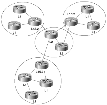
An intermediate system can be a level 1 (L1) router, a level 2 (L2) router, or both (L1/L2). L1 routers are analogous to OSPF nonbackbone Internal Routers, L2 routers are analogous to OSPF backbone routers, and L1/L2 routers are analogous to OSPF ABRs. In Figure 10-3, the L1/L2 routers are connected to L1 routers and to L2 routers. These L1/L2 routers must maintain both a level 1 link-state database and a level 2 link-state database, in much the same way that an OSPF ABR must maintain a separate database for each area to which it is attached. Cisco routers are configured as L1-only, L2-only, or L1/L2 with the command is-type. By default, they are L1/L2.
While the area topology shown in Figure 10-3 is useful for contrasting IS-IS areas with OSPF areas, it can also be slightly misleading; IS-IS areas are not quite as clear-cut as OSPF areas are. Rather than think of them as topological areas, IS-IS areas are best thought of as a set of adjacencies. An adjacency, in turn, can be either L1 or L2. So, for example, a given L1 area is actually a contiguous set of L1 adjacencies between routers with the same AID. This is especially important for understanding L2 areas, which are always defined as a set of L2 adjacencies. An L1/L2 router, then, is a router in an L1 area that has both one or more L1 adjacencies and one or more L2 adjacencies. An L2 router is one that has only L2 adjacencies.
It is also possible for both an L1 and an L2 adjacency to exist between two neighbors; because IS-IS areas are defined as a series of adjacencies, the implication of having both an L1 and an L2 adjacency between the same two neighbors is that IS-IS areas can overlap. This is in contrast to OSPF, in which area boundaries are more distinct.
As with OSPF, inter-area traffic must traverse an L2 area to prevent inter-area routing loops. Every L1 router within an area (including the area’s L1/L2 routers) maintains an identical link-state database. Unlike OSPF ABRs, L1/L2 routers do not by default advertise L2 routes to L1 routers. Therefore, an L1 router has no knowledge of destinations outside of its own area. In this sense, an L1 area is similar to an OSPF totally stubby area. To route a packet to another area, an L1 router must forward the packet to an L1/L2 router. When an L1/L2 router sends its level 1 LSP into an area, it signals other L1 routers that it can reach another area by setting a bit known as the Attached (ATT) bit[9] in the LSP.
ISO 10589 describes a procedure by which IS-IS routers can create virtual links to repair partitioned areas, just as OSPF can. This feature is not supported by Cisco or by most other router vendors and is not further described here. The primary reason vendors do not support IS-IS virtual links is simply that their customers have not asked for them, and this goes to a fundamental difference in OSPF and IS-IS application. OSPF, with its rich area utilities and feature set, is the protocol of choice for enterprise networks. Multi-area IS-IS, on the other hand, is more complex to run and so is seldom if ever found in enterprise networks. Carriers and ISPs run BGP-based networks, and their IGP is used mainly for finding BGP session endpoints. So they want their IGP to be as simple as possible—often making their entire routing domain a single IGP area. IS-IS is certainly simpler than OSPF in many aspects, and many will argue that it is more scalable in this type of “single large area” application. So when you encounter IS-IS in a service provider network, what you will usually encounter is a single L2 area.[10]
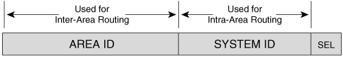
Because an IS-IS router resides completely within a single area, the Area ID (or area address) is associated with the entire router rather than an interface. A unique feature of IS-IS is that a router can have, by default, up to three area addresses, which can be useful during area transitions. Using the IOS command max-area-addresses, you can increase an area’s addresses up to 254. A configuration case study later in this chapter, “An Area Migration,” demonstrates the use of multiple area addresses. Each IS-IS router must also have a way to uniquely identify itself within the routing domain. This identification is the function of the System ID, which is analogous to the OSPF Router ID. Both the Area ID and the System ID are defined on an IS-IS router by a single address, the Network Entity Title (NET).
Even when IS-IS is used to route only TCP/IP, IS-IS is still an ISO CLNP protocol. Consequently, the packets by which IS-IS communicates with its peers are CLNS PDUs, which in turn means that even in an IP-only environment, an IS-IS router must have an ISO address. The ISO address is a network address, known as Network Entity Title (NET), described in ISO 8348.[11] The length of a NET can range from 8 to 20 octets; the NET describes both the Area ID and the System ID of a device, as shown in Figure 10-4.
The ISO designed the NET to be many things to many systems, and depending upon your viewpoint, the address format is either extremely flexible and scalable or it is a cumbersome muddle of variable fields. Figure 10-5 shows just three of the many forms an ISO NET can take. Although the fields preceding the System ID are different in each example, the System ID itself is the same. ISO 10589 specifies that the field can be from one to eight octets in length, but that the System ID of all nodes within the routing domain must use the same length. In practice, the length is always six octets[12] and is often adapted from the Media Access Control (MAC) identifier of an interface on the device. The System ID must be unique for each node within the routing domain.
![Three NET formats: A simple eight-octet Area ID/System ID format (a); an OSI NSAP format (b); and a GOSIP NSAP formatGOSIP Advanced Requirements Group, “Government Open Systems Interconnection Profile (GOSIP) Version 2.0 [Final Text],” Federal Information Processing Standard, U.S. Department of Commerce, National Institute of Standards and Technology, October 1990. (c).](http://imgdetail.ebookreading.net/system_admin/3/1587052024/1587052024__routing-tcpip-volume__1587052024__graphics__10fig05.gif)
Figure 10-5. Three NET formats: A simple eight-octet Area ID/System ID format (a); an OSI NSAP format (b); and a GOSIP NSAP format[13] (c).
Also of interest in the examples of Figure 10-5 is the NSAP Selector (SEL). In each case, this one-octet field is set to 0x00. A Network Service Access Point (NSAP) describes an attachment to a particular service at the network layer of a node. So when the SEL is set to something other than 0x00 in an ISO address the address is an NSAP address. This situation is similar to the combination of IP destination address and IP protocol number in an IP packet, which addresses a particular service at the network layer of a particular device’s TCP/IP stack. When the SEL is set to 0x00 in an ISO address, the address is a NET, the address of a node’s network layer itself.
As the variety of formats in Figure 10-5 implies, a detailed discussion of the configuration of NETs is beyond the scope of this book. A good reference for further study is RFC 1237.[14] In an IP-only environment, the NET might be assigned based on a standard such as GOSIP. If you are free to choose any NET for an IP-only environment, choose the simplest format that will serve the needs of your network.
Regardless of the format, the following three rules apply:
The NET must begin with a single octet (for example, 47.xxxx. . .).
The NET must end with a single octet, which should be set to 0x00 (. . .xxxx.00). IS-IS will function if the SEL is nonzero but a dual CLNP/IP router might experience problems.
On Cisco routers, the System ID of the NET must be six octets.
One of the primary reasons for having a layered network architecture like the OSI model is so that the functions of each layer are independent from the layer below. The network layer, for example, must adapt to many types of data links, or subnetworks. To further this adaptability, the network layer consists of two sublayers (Figure 10-6). The Subnetwork Independent sublayer provides consistent, uniform network services to the transport layer. The Subnetwork Dependent sublayer accesses the services of the data-link layer on behalf of the Subnetwork Independent sublayer. As the two names imply, the Subnetwork Dependent sublayer depends upon a specific type of data link, so that the Subnetwork Independent sublayer can be independent of the data link.
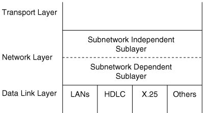
The organization of the network layer, specified in ISO 8648,[15] is actually more complex than that shown in Figure 10-6. The two basic sublayers are introduced here because ISO 10589 presents much of its description of the operation of IS-IS within the framework of the functions of these sublayers.
The subnetwork dependent functions are, of course, the functions of the Subnetwork Dependent sublayer. Their job is to hide the characteristics of different kinds of data links (subnetworks) from the functions of the Subnetwork Independent sublayer. The following subnetwork dependent functions are important to routing:
The transmission and reception of PDUs over the specific attached subnetwork
The exchange of IS-IS Hello PDUs to discover neighbors and establish adjacencies on the subnetwork
The maintenance of the adjacencies
Link demultiplexing, or the transfer of OSI PDUs to the OSI process and the transfer of IP packets to the IP process
In contrast to the four network types defined by OSPF, IS-IS defines only two: broadcast subnetworks and point-to-point or general topology subnetworks. Broadcast subnetworks are defined the same as they are under OSPF—multi-access data links that support multicasting. Point-to-point (nonbroadcast) subnetworks can be permanent, such as a T1 link, or dynamically established, such as X.25 SVCs.
IS-IS routers discover neighbors and form adjacencies by exchanging IS-IS Hello PDUs. Hellos are transmitted every 10 seconds, and on Cisco routers this interval can be changed on a per interface basis with the command isis hello-interval. Although IS-IS Hellos are slightly different for broadcast and point-to-point subnetworks, the Hellos include the same essential information, described in the section “IS-IS PDU Formats.” An IS-IS router uses its Hello PDUs to identify itself and its capabilities and to describe the parameters of the interface on which the Hellos are sent. If two neighbors are in agreement about their respective capabilities and interface parameters, they become adjacent. IS-IS is, however, less strict than OSPF in accepting adjacencies. In most cases, capabilities advertised by one neighbor but not supported by the other neighbor will not prevent an adjacency from forming; the capability is just ignored. The neighbors can even advertise different Hello intervals.
IS-IS forms separate adjacencies for L1 and L2 neighbors. L1-only routers form L1 adjacencies with L1 and L1/L2 neighbors, and L2-only routers form L2 adjacencies with L2 and L1/L2 neighbors. Neighboring L1/L2 routers can form both an L1 adjacency and an L2 adjacency. An L1-only router and an L2-only router will not establish an adjacency. As mentioned previously, Cisco routers are by default L1/L2.
While the type of router (L1-only, L2-only, or L1/L2) influences the type of adjacency that is formed, so do the area IDs configured on the two neighbors in question. The following rules apply:
Two L1-only routers form an L1 adjacency only if their AIDs match.
Two L2-only routers form an L2 adjacency, even if their AIDs are different.
An L1-only router forms an L1 adjacency with an L1/L2 router only if their AIDs match.
An L2-only router forms an L2 adjacency with an L1/L2 router even if their AIDs are different.
Two L1/L2 routers form both L1 and L2 adjacencies if their AIDs match.
Two L1/L2 routers form only an L2 adjacency if their AIDs do not match.
Once an adjacency is established, the Hellos act as keepalives. Each router sends a hold time in its Hellos, informing its neighbors how long they should wait to hear the next Hello before declaring the router dead. The default hold time on Cisco routers is three times the Hello interval and can be changed on a per interface basis with the command isis hello-multiplier. A significant difference from OSPF is that the hello intervals and hold times between two IS-IS neighbors do not have to match. Each router honors the hold time advertised by its neighbor.
Another interesting difference between OSPF and IS-IS adjacencies is when two routers become adjacent. OSPF can be a bit confusing here; two routers are considered adjacent as soon as two-way communication is established, but not fully adjacent until database synchronization is completed. IS-IS considers routers adjacent as soon as they have exchanged Hellos.
The IS-IS neighbor table can be observed with the command show clns is-neighbors (Example 10-1). The first four columns of the display show the System ID of each neighbor, the interface on which the neighbor is located, the state of the adjacency, and the adjacency type. The state will be either Init, indicating that the neighbor is known, but is not adjacent, or Up, indicating that the neighbor is adjacent. The priority is the router priority used for electing a Designated Router on a broadcast network, as described in the next section.
Example 10-1. The command show clns is-neighbors displays the IS-IS neighbor table.
Brussels#show clns is-neighbors
System Id      Interface  State  Type  Priority  Circuit Id         Format
0000.0C04.DCC0 Se0        Up     L1    0         06                 Phase V
0000.0C04.DCC0 Et1        Up     L1    64        0000.0C76.5B7C.03  Phase V
0000.0C0A.2C51 Et0        Up     L2    64        0000.0C76.5B7C.02  Phase V
0000.0C0A.2AA9 Et0        Up     L1L2  64/64     0000.0C76.5B7C.02  Phase V
Brussels#
The sixth column shows the Circuit ID, a one-octet number that the router uses to uniquely identify the IS-IS interface. If the interface is attached to a broadcast multiaccess network, the Circuit ID is concatenated with the System ID of the network’s Designated Router, and the complete number is known as the LAN ID. In this usage, the Circuit ID is more correctly called the Pseudonode ID. For example, in Example 10-1 the LAN ID of the link attached to interface E0 is 0000.0c76.5b7c.02. The System ID of the Designated Router is 0000.0c76.5b7c, and the Pseudonode ID is 02.
The last column indicates the format of the adjacency. For Integrated IS-IS the format will always be Phase V, indicating OSI/DECnet Phase V. The only other adjacency format is DECnet Phase IV.
IS-IS elects a Designated Router (or more officially, a Designated IS) on broadcast multi-access networks for the same reason OSPF does. Rather than having each router connected to the LAN advertise an adjacency with every other router on the network, the network itself is considered a router—a pseudonode. Each router, including the Designated Router, advertises a single link to the pseudonode. The DR also advertises, as the representative of the pseudonode, a zero-cost link to all of the attached routers.
Unlike OSPF, however, an IS-IS router attached to a broadcast multi-access network establishes adjacencies with all of its neighbors on the network, not just the DR. This is in keeping with the mention in the previous section that IS-IS adjacencies are established as soon as Hellos are exchanged. Each router multicasts its LSPs to all of its neighbors, and the DR uses a system of PDUs called Sequence Number PDUs (SNPs) to ensure that the flooding of LSPs is reliable. The reliable flooding process, and SNPs, are described in a later section, “Update Process.”
The IS-IS Designated Router election process is quite simple. Every IS-IS router interface is assigned both an L1 priority and an L2 priority in the range of 0 to 127. Cisco router interfaces have a default priority of 64 for both levels, and this value can be changed with the command isis priority.
The router advertises its priority in the Hellos sent from each interface—the L1 priority is advertised in L1 Hellos, and the L2 priority is advertised in L2 Hellos. Unlike OSPF, in which a priority of 0 makes the router ineligible to become the DR, an IS-IS router with a priority of 0 is merely the lowest priority, but can still become the DR. Interfaces to nonbroadcast networks, on which a DR is not elected, always have a priority of 0 (notice the priority of the serial interface in Example 10-1). The router with the highest priority becomes the DR. In a tie, the router whose attached interface has the numerically highest MAC address becomes the DR.
As the L1 and L2 priorities suggest, separate DRs are elected on a network for level 1 and level 2. This outcome is necessary because of the separate L1 and L2 adjacencies that can exist on a single LAN, as shown in Figure 10-7. Because an interface can have separate priorities for each level, the L1 DR and the L2 DR on a LAN might or might not be the same router.
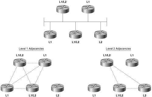
Figure 10-7. Separate adjacencies are established for level 1 and for level 2, so separate DRs must be elected for level 1 and level 2.
The DR assigns the LAN ID to the network. As discussed in the preceding section, the LAN ID is a concatenation of the DR’s System ID and its Pseudonode ID for the attached network. All other routers on the network will use the LAN ID assigned by the DR.
Example 10-2 shows the neighbor table of a router whose E0 interface is attached to the same network as the E0 interface of the router of Example 10-1. By comparing these two tables, you can see that three routers are attached to the Ethernet: 0000.0c0a.2aa9, 0000.0c0a.2c51, and 0000.0c76.5b7c. All have a priority of 64, so the one with the numerically highest MAC address is the DR. That router, 0000.0c76.5b7c, identifies the network with Circuit ID 02. Therefore, the LAN ID shown in both Example 10-1 and Example 10-2 is 0000.0c76.5b7c.02.
Appending the Circuit ID to the System ID is necessary because the same router can be the DR on more than one network. Notice in Example 10-1 that the same router is the DR on the network attached to E0 and the network attached to E1. It is the Circuit ID, 02 on E0 and 03 on E1, which makes the LAN ID unique for each network.
Example 10-2. The E0 interface of this router is attached to the same network as the E0 interface of the router in Example 10-1.
London#show clns is-neighbors
System Id       Interface  State  Type  Priority  Circuit Id         Format
0000.0C76.5B7C  Et0        Up     L2    64        0000.0C76.5B7C.02  Phase V
0000.0C0A.2AA9  Et0        Up     L2    64        0000.0C76.5B7C.02  Phase V
0000.3090.6756  Se0        Up     L1    0         02                 Phase V
London#
The IS-IS DR process is more primitive (or less complex, depending upon one’s viewpoint) than the OSPF DR process in two ways. First, IS-IS does not elect a Backup Designated Router. If the IS-IS DR fails, a new DR is elected. Second, the IS-IS DR is not as stable as the OSPF DR. If an OSPF router becomes active on a network with an existing DR, the new router will not become the DR even if its priority or Router ID is higher. As a result, the OSPF DR usually is the router that has been active on the network for the longest time. In contrast to the OSPF rules, a new IS-IS router with a higher priority than the existing DR, or an equal priority and a higher MAC address, will become the new DR. Each time the DR is changed, a new set of LSPs must be flooded. However, given that adding a new router to a broadcast link is a relatively uncommon occurrence in the operational day of a network, and that DR election happens very quickly in modern routers—on the order of microseconds—the lack of a BDR and the fact that a DR can be preempted should not be a cause for concern.
The functions of the subnetwork-independent sublayer define how CLNS delivers packets throughout the CLNP network and how these services are offered to the transport layer. The routing function itself is divided into four processes: the Update process, the Decision process, the Forwarding process, and the Receive process. As the names of the last two processes suggest, the Forwarding process is responsible for transmitting PDUs, and the Receive process is responsible for the reception of PDUs. These two processes, as described in ISO 10589, are more relevant to CLNS NPDUs than to IP packets, and so are not described further.
The Update process is responsible for constructing the L1 and L2 link-state databases. To do so, L1 LSPs are flooded throughout the area in which they are originated, and L2 LSPs are flooded over all L2 adjacencies. The specific fields of the LSPs are described in the section “IS-IS PDU Formats.”
Each LSP contains a Remaining Lifetime, a Sequence Number, and a Checksum. The Remaining Lifetime is an age. The difference between an IS-IS LSP’s Remaining Lifetime and an OSPF LSA’s Age parameter is that the LSA Age increments from zero to MaxAge, whereas the LSP Remaining Lifetime begins at MaxAge and decrements to zero. The IS-IS MaxAge is 1200 seconds (20 minutes). Like OSPF, IS-IS ages each LSP as it resides in the link-state database, and the originator must periodically refresh its LSAs to prevent the Remaining Lifetime from reaching zero. The IS-IS refresh interval is 15 minutes minus a random jitter of up to 25 percent. If the Remaining Lifetime reaches zero, the expired LSP will be kept in the link-state database for 60 seconds, known as the ZeroAgeLifetime.
An interesting and important difference from the OSPF LSA refresh process is that because the IS-IS Remaining Lifetime begins as a non-zero number and is decremented down to zero, the beginning number can be changed from its default of 1200 seconds. In fact, it can be increased up to 65,535 seconds—approximately 18.2 hours. This is a major contributing factor to IS-IS scalability in very large areas. If the area links are reasonably stable, increasing the refresh time and the Remaining Lifetime can sharply reduce the flooding load caused by LSP refreshes. The initial Remaining Lifetime (MaxAge) value that is set in locally originated LSPs is changed with the command max-lsp-lifetime, and the period between refreshes of locally originated LSPs is set with the command lsp-refresh-interval. If you change the defaults, always set the refresh interval at least a few hundred seconds less than the Remaining Lifetime so that newly refreshed LSPs arrive at all routers in the area before the old instances of the LSPs age out.
Under older IS-IS procedures, if any router receives an LSP with an incorrect checksum, the router will purge the LSP by setting the LSP’s Remaining Lifetime to zero and reflooding it. The purge causes the LSP’s originator to send a new instance of the LSP. However, the second edition of ISO 10589 does away with purging LSPs with incorrect checksums because on error-prone subnetworks, allowing receiving routers to initiate purges can significantly increase the LSP traffic.
IOS implementations before 12.0 follow the older purging procedure, but you can override this behavior with the command ignore-lsp-errors. When a router with this option enabled receives a corrupted LSP, it drops it rather than purging it. The originator of the corrupted LSP will still know that the LSP was not received through the use of SNPs, described later in this section. As of 12.0, the newer IS-IS procedures are implemented and ignore-lsp-errors is enabled by default.
A significant point about the LSP purging, however, is yet another way that IS-IS differs from OSPF, where only the originator can purge an OSPF LSA.
The Sequence Number is an unsigned, 32-bit linear number. When a router first originates an LSP, it uses a Sequence Number of one, and each subsequent instance of the LSP has its Sequence Number incremented by one. If the Sequence Number increments to the maximum (0xFFFFFFFF), the IS-IS process must shut down for at least 21 minutes (MaxAge + ZeroAgeLifetime) to allow the old LSPs to age out of all databases.
On point-to-point subnetworks, routers send L1 and L2 LSPs directly to the neighboring router. On broadcast subnetworks, the LSPs are multicast to all neighbors. Frames carrying L1 LSPs have a destination MAC identifier of 0180.c200.0014, known as AllL1ISs. Frames carrying L2 LSPs have a destination MAC identifier of 0180.c200.0015, known as AllL2ISs.
IS-IS uses SNPs both to acknowledge the receipt of LSPs, to request LSPs, and to help maintain link-state database synchronization. There are two types of SNPs: Partial SNPs (PSNP) and Complete SNPs (CSNP). On a point-to-point subnetwork, a router uses a PSNP to explicitly acknowledge each LSP it receives.[16] The PSNP describes the LSP it is acknowledging by including the following information:
The LSP ID
The LSP’s Sequence Number
The LSP’s checksum
The LSP’s Remaining Lifetime
When a router sends an LSP on a point-to-point subnetwork, it sets a timer for a period known as minimumLSPTransmissionInterval. If the timer expires before the router receives a PSNP acknowledging receipt of the LSP, a new LSP will be sent. On Cisco routers, the default minimumLSPTransmissionInterval is five seconds. It can be changed on a per interface basis with the command isis retransmit-interval. The default value is almost always the right value; the occasional exception is if a neighbor regularly struggles to process a large number of LSPs. In this case the router might not acknowledge an LSP fast enough, triggering a retransmit and just adding to its problems. In this case, increasing the minimumLSPTransmissionInterval can help; but in the long run, the real solution to such a problem is upgrading the low-powered neighbor.
On broadcast subnetworks, LSPs are not acknowledged by each receiving router. Instead, the DR periodically multicasts a CSNP that describes every LSP in the link-state database. The default CSNP period is 10 seconds, which can be changed with the command isis csnp-interval. L1 CSNPs are multicast to AllL1ISs (0180.c200.0014), and L2 CSNPs are multicast to AllL2ISs (0180.c200.0015).
When a router receives a CSNP, it compares the LSPs summarized in the PDU with the LSPs in its database. If the router has an LSP that is missing from the CSNP or a newer instance of an LSP, the router multicasts the LSP onto the network. If another router sends the updated LSP first, however, the router will not send another copy of the same LSP. If the router’s database does not contain a copy of every LSP listed in the CSNP or if the database contains an older instance of an LSP, the router multicasts a PSNP listing the LSPs it needs. Although the PSNP is multicast, only the DR responds with the appropriate LSPs.
An interesting feature of IS-IS is its ability to signal other routers if it runs out of memory and cannot record the complete link-state database. The memory overload might be due to an area that has been allowed to grow too large, a router with insufficient memory, or a transitory condition such as the failure of a DR. If a router cannot store the complete link-state database, it will set a bit in its LSP called the Overload (OL) bit.
The OL bit signals that the router might not be able to make correct routing decisions because of its incomplete database. The other routers still route packets to the overloaded router’s directly connected networks, but do not use the router for transit traffic until it has issued an LSP with the OL bit cleared. Because a set OL bit prevents the router from being used as a hop along a route, the bit is frequently called the hippity bit (as in hippity-hop, believe it or not). Memory should be allocated equally to the L1 and the L2 database, but a router can be in an overload condition at one level and normal in the other.
This overload feature is an artifact of the days when routers did not have much memory. Modern routers are unlikely to become overloaded. However, the OL bit serves another very useful purpose in modern networks, particularly in BGP networks. To understand the problem, it is necessary to understand a few basic concepts of BGP. While link-state protocols such as IS-IS converge very quickly, BGP converges slowly—sometimes taking several minutes. In the interior of a BGP network, routes have next-hop addresses that can be several router hops away. When a packet arrives, its destination is looked up in the BGP routes. The next hop of the BGP route must then be looked up in the IGP routes before the packet can be forwarded.
Now suppose that a new router is added to the network, and the IGP has converged but BGP has not yet finished. If another router determines that this new router is on the best path to a BGP next-hop, based on the converged IGP routes, it will forward packets to the router to be forwarded along to the next-hop address. But if BGP has not yet converged in the new router, the router might not have a BGP route for the packet and might drop it, resulting in black-holed traffic.
By setting the IS-IS OL bit until BGP has converged, you can avoid this problem. Other routers, if the OL bit is set, will route around the new router. Once BGP is converged, the OL bit can be cleared and packets can be forwarded through the new router.
Using the command set-overload-bit on-startup, you can specify a number of seconds by which the OL bit is set whenever IS-IS starts. When the specified seconds expire, the OL bit is automatically cleared. By setting the OL bit at around 300 to 500 seconds, you ensure that BGP will converge before the OL bit is cleared. There is an alternative command, set-overload-bit on-startup wait-for-bgp, which always clears the OL bit as soon as BGP converges. While more dynamic than using a static number of seconds, this option can have a vulnerability: If one BGP session does not come up for some reason, the OL bit will never be cleared. So it is usually best to specify seconds rather than the wait-for-bgp option.
You can also set the OL bit manually and indefinitely by using the set-overload-bit command with no other options specified. This can be useful in situations where you want the router to be attached to an IS-IS network and receive a full database, but you do not want the router to be used in any forwarding path. A lab router attached to a production network is an example of such an application.
The command show isis database displays a summary of the IS-IS link state database, as shown in Example 10-3. The router Brussels in this display is an L1/L2 router, so it has both L1 and L2 databases. The LSP ID shown in the first column consists of the System ID of the originating router, concatenated with two more octets. The first octet following the System ID is the Pseudonode ID. If this octet is nonzero, the LSP was originated by a DR. The System ID and the nonzero Pseudonode ID together make the LAN ID of a broadcast subnetwork.
Example 10-3. The IS-IS database can be observed with the command show isis database.
Brussels#show isis database
IS-IS Level-1 Link State Database
LSPID                  LSP Seq Num  LSP Checksum  LSP Holdtime  ATT/P/OL
0000.0C04.DCC0.00-00   0x00000036   0x78AE        1152          0/0/0
0000.0C0A.2AA9.00-00   0x0000011B   0x057B        416           0/0/0
0000.0C76.5B7C.00-00*  0x00000150   0xD5D4        961           1/0/0
0000.0C76.5B7C.02-00*  0x00000119   0xD9C3        407           0/0/0
0000.0C76.5B7C.03-00*  0x000000FA   0x896E        847           0/0/0
IS-IS Level-2 Link State Database
LSPID                  LSP Seq Num  LSP Checksum  LSP Holdtime  ATT/P/OL
0000.0C0A.2AA9.00-00   0x0000013E   0x319A        666           0/0/0
0000.0C0A.2C51.00-00   0x00000133   0x762D        654           0/0/0
0000.0C76.5B7C.00-00*  0x0000014C    0x4E91       886           0/0/0
0000.0C76.5B7C.02-00*  0x0000011F   0x3CC3        1174          0/0/0
0000.3090.C7DF.00-00   0x0000011A   0xDDF0        858           0/0/0
Brussels#
The last octet is the LSP Number. Occasionally, an LSP can be so large that it exceeds the MTU that can be supported by the router buffers or the data link. In this case, the LSP is fragmented—that is, the information is conveyed in multiple LSPs. The LSP IDs of these multiple LSPs consist of identical System IDs and Pseudonode IDs, and distinct LSP Numbers.
An asterisk following the LSP ID indicates that the LSP is originated by the router on which the database is being observed. For example, the database shown in Example 10-3 is taken from a router named Brussels. The L1 LSP with an ID of 0000.0c76.5bB7c.00-00 is originated by Brussels, as are four other LSPs.
The second and third columns of the database display show the Sequence Number and checksum of each LSP. The fourth column, LSP Holdtime, is the Remaining Lifetime of the LSP in seconds. If you enter the show isis database command repeatedly, you can observe the numbers decrementing. When the LSP is refreshed, the Remaining Lifetime is reset to 1200 seconds and the Sequence Number is incremented by one.
The last column indicates the state of the Attached (ATT) bit, Partition (P) bit, and Overload (OL) bit of each LSP. L2 and L1/L2 routers will set the ATT bit to one to indicate that they have a route to another area. The P bit indicates that the originating router has partition repair capability. Cisco (and most other vendors) does not support this function, so the bit is always set to zero. The OL bit is set to one if the originating router is experiencing a memory overload and has an incomplete link-state database, or if the OL bit has been manually set.
A complete LSP can be observed by using the command show isis database detail along with the level and the LSP ID, as shown in Example 10-4. The meanings of the individual fields of the LSP are given in the section “IS-IS PDU Formats.”
Example 10-4. The command show isis database detail is used to observe complete LSPs in the database.
London#show isis database detail level-2 0000.0C0A.2C51.00-00
IS-IS Level-2 LSP 0000.0C0A.2C51.00-00
LSPID                  LSP Seq Num  LSP Checksum  LSP Holdtime  ATT/P/OL
0000.0C0A.2C51.00-00*  0x0000013B   0x6635        815           0/0/0
  Area Address: 47.0001
  NLPID:      0x81 0xCC
  IP Address: 10.1.3.2
  Metric: 10 IS 0000.0C76.5B7C.02
  Metric: 10 IP 10.1.3.0 255.255.255.0
  Metric: 20 IP 10.1.2.0 255.255.255.0
  Metric: 10 IP 10.1.255.4 255.255.255.252
  Metric: 20 IP 10.1.255.0 255.255.255.0
  Metric: 30 IP 10.1.255.8 255.255.255.252
London#Once the Update process has built the link-state database, the Decision process uses the information in the database to calculate a shortest-path tree. The process then uses the shortest-path tree to construct a forwarding database (route table). Separate SPF calculations are run for the L1 database and the L2 database.
ISO 10589 specifies the following metrics (one required and three optional) to be used by IS-IS to calculate the shortest path:
Default—. This metric must be supported and understood by every IS-IS router.
Delay—. This optional metric reflects the transit delay of a subnetwork.
Expense—. This optional metric reflects the monetary cost of using the subnetwork.
Error—. This optional metric reflects the residual error probability of the subnetwork, similar to the IGRP/EIGRP reliability metric.
Each metric is expressed as an integer between 0 and 63, and a separate route is calculated for each metric. Therefore, if a system supports all four metrics, the SPF calculation must be run four times for both the L1 database and the L2 database. Because of the potential for many iterations of the SPF calculation for every destination, resulting in many different route tables, and because the optional metrics provide rudimentary Type of Service routing at best, Cisco supports only the default metric.
Cisco assigns a default metric of 10 to every interface, regardless of the interface type. The command isis metric changes the value of the default metric, and the default can be changed separately for level 1 and level 2. If the metrics are left at 10 for every interface, every subnetwork is considered equal and the IS-IS metric becomes a simple measure of hop count, where each hop has a cost of 10.
The total cost of a route is a simple sum of the individual metrics at each outgoing interface, and the maximum metric value that can be assigned to any route is 1023. This small maximum is frequently pointed out as a limitation of IS-IS because it leaves little room for metric granularity in large networks.
However, newer extensions to IS-IS allow for a much larger metric space—called wide metrics—of 32 bits. To set wide metrics, the command metric-style wide is used.
IS-IS not only classifies routes as L1 or L2 but also classifies routes as internal or external. Internal routes are paths to destinations within the IS-IS routing domain, and external routes are paths to destinations external to the routing domain. Whereas L2 routes may be either internal or external, L1 routes are normally internal; using a routing policy you can make an L1 route external, but this should only be done with good justification and with special care.
Given multiple possible routes to a particular destination, an L1 path is preferred over an L2 path. Within each level, a path that supports the optional metrics is preferred over a path that supports only the default metric. (Again, Cisco supports only the default metric, so the second order of preference is not relevant to Cisco routers.) Within each level of metric support, the path with the lowest metric is preferred. If multiple equal-cost, equal-level paths are found by the Decision process, they are all entered into the route table. The Cisco IS-IS implementation usually performs equal-cost load balancing on up to six paths.
The previous section, “Update Process,” discussed the last octet of the LSP ID, known as the LSP Number, used to track fragmented LSPs. The Decision process pays attention to the LSP Number for several reasons. First, if an LSP with an LSP Number of zero and a nonzero Remaining Lifetime is not present in the database, the Decision process will not process any LSPs from the same system that have nonzero LSP Numbers. For example, if the LSP IDs 0000.0c76.5b7c.00-01 and 0000.0c76.5b7c.00-02 exist in the database, but the database contains no LSP with an LSP ID of 0000.0c76.5b7c.00-00, the first two LSPs are not processed. This approach ensures that incomplete LSPs do not cause inaccurate routing decisions.
Also, the Decision process will accept the following information only from LSPs whose LSP Number is zero:
The setting of the Database Overload bit
The setting of the IS Type field
The setting of the Area Addresses option field
The Decision process ignores these settings in LSPs whose LSP Number is nonzero. In other words, the first LSP in a series of fragments speaks for all the fragments for these three settings.
Example 10-5 shows a route table from a Cisco IS-IS router. Notice that the L1 and L2 routes are indicated and that three destinations have multiple paths. A mask is associated with each route, indicating support for VLSM. Finally, the route table indicates that the administrative distance of IS-IS routes is 115.
Example 10-5. This route table shows both level 1 and level 2 IS-IS routes.
Brussels#show ip route
Codes: C - connected, S - static, I - IGRP, R - RIP, M - mobile, B - BGP
       D - EIGRP, EX - EIGRP external, O - OSPF, IA - OSPF inter area
       E1 - OSPF external type 1, E2 - OSPF external type 2, E - EGP
       i - IS-IS, L1 - IS-IS level-1, L2 - IS-IS level-2, * - candidate default
Gateway of last resort is not set
     10.0.0.0 is variably subnetted, 8 subnets, 3 masks
C       10.1.3.0 255.255.255.0 is directly connected, Ethernet0
i L2    10.1.2.0 255.255.255.0 [115/30] via 10.1.3.2, Ethernet0
                               [115/30] via 10.1.3.3, Ethernet0
i L1    10.1.5.0 255.255.255.0 [115/20] via 0.0.0.0, Serial0
                               [115/20] via 10.1.4.2, Ethernet1
C       10.1.4.0 255.255.255.0 is directly connected, Ethernet1
i L2    10.1.255.4 255.255.255.252 [115/20] via 10.1.3.2, Ethernet0
i L2    10.1.255.0 255.255.255.0 [115/30] via 10.1.3.2, Ethernet0
i L1    10.1.255.8 255.255.255.252 [115/20] via 10.1.3.3, Ethernet0
i L1    10.1.6.240 255.255.255.240 [115/20] via 0.0.0.0, Serial0
                                   [115/20] via 10.1.4.2, Ethernet1
Brussels#
Another duty of the Decision process in L1 routers is to calculate the path to the nearest L2 router, for inter-area routing. As previously discussed, when an L2 or L1/L2 router is attached to another area, the router will advertise the fact by setting the ATT bit in its LSP to one. The Decision process in L1 routers will choose the metrically closest L1/L2 router as the default inter-area router. When IS-IS is used to route IP, a default IP route to the L1/L2 is entered into the route table. For example, Example 10-6 shows a link-state database for an L1 router and its associated route table. LSP 0000.0c0a.2c51.00-00 has an ATT = 1. Based upon this information, the Decision process has chosen the router with System ID 0000.0c0a.2c51 as the default inter-area router. The route table shows a default route (0.0.0.0) via 10.1.255.6, with a metric of 10. Although it is not readily apparent from the information shown in Example 10-6, 10.1.255.6 and System ID 0000.0c0a.2c51 refer to the same router.
Example 10-6. Integrated IS-IS adds a default IP route to the nearest L1/L2 router whose ATT bit is set to one.
Paris#show isis database
IS-IS Level-1 Link State Database
LSPID                  LSP Seq Num  LSP Checksum  LSP Holdtime  ATT/P/OL
0000.0C0A.2C51.00-00   0x0000016D   0xA093        730           1/0/0
0000.3090.6756.00-00*  0x00000167   0xC103        813           0/0/0
0000.3090.6756.04-00*  0x0000014E   0x227F        801           0/0/0
0000.3090.C7DF.00-00   0x00000158   0x78A6        442           0/0/0
Paris#show ip route
Codes: C - connected, S - static, I - IGRP, R - RIP, M - mobile, B - BGP
       D - EIGRP, EX - EIGRP external, O - OSPF, IA - OSPF inter area
       E1 - OSPF external type 1, E2 - OSPF external type 2, E - EGP
       i - IS-IS, L1 - IS-IS level-1, L2 - IS-IS level-2, * - candidate default
Gateway of last resort is 10.1.255.6 to network 0.0.0.0
     10.0.0.0 is variably subnetted, 5 subnets, 2 masks
i L1    10.1.3.0 255.255.255.0 [115/20] via 10.1.255.6, Serial0
C       10.1.2.0 255.255.255.0 is directly connected, TokenRing0
i L1    10.1.255.4 255.255.255.252 [115/20] via 10.1.255.6, Serial0
C       10.1.255.0 255.255.255.0 is directly connected, Serial0
i L1    10.1.255.8 255.255.255.252 [115/20] via 10.1.2.2, TokenRing0
i*L1 0.0.0.0 0.0.0.0 [115/10] via 10.1.255.6, Serial0
Paris#
The information in Example 10-6 illustrates an interesting characteristic of working with Integrated IS-IS, particularly when troubleshooting. Although TCP/IP is the protocol being routed, the protocol determining the routes, including all the route control packets and addresses, is a CLNS protocol. Sometimes correlating the CLNS information with the IP information can be difficult. One command that can be useful is which-route.
The command is used primarily to determine the route table in which a particular CLNS destination is located. However, which-route can also yield useful information about the IP addresses associated with a particular CLNS address. In Example 10-7, the System ID/Circuit ID 0000.0c0a.2c51.00, shown in the database of Example 10-6 as having ATT = 1, is used as the argument to which-route. The result shows, among other things, that the next-hop address for the queried System ID is 10.1.255.6.
Example 10-7. The command which-route can reveal some information tying CLNS addresses to IP addresses.
Paris#which-route 0000.0C0A.2C51.00
Route look-up for destination 00.000c.0a2c.5100
  Using route to closest IS-IS level-2 router
Adjacency entry used:
System Id        SNPA      Interface   State   Holdtime   Type   Protocol
0000.0C0A.2C51   *HDLC*    Se0         Up      26         L1     IS-IS
  Area Address(es): 47.0001
  IP Address(es): 10.1.255.6
  Uptime: 22:08:52
Paris#
IS-IS uses nine PDU types in its processes, and each PDU is identified by a five-bit type number. The PDUs fall into three categories, as shown in Table 10-1.
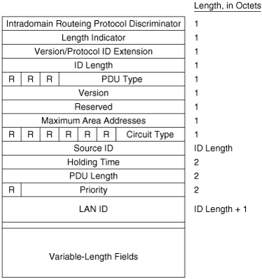
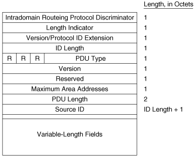
The first eight octets of all of the IS-IS PDUs are header fields that are common to all PDU types, as shown in Figure 10-8. These first fields are described here, and the PDU-specific fields are described in subsequent sections.

Intradomain Routeing Protocol Discriminator is a constant assigned by ISO 9577[17] to identify NPDUs. All IS-IS PDUs have a value of 0x83 in this field.
Length Indicator specifies the length of the fixed header in octets.
Version/Protocol ID Extension is always set to one.
ID Length describes the length of the System ID field of NSAP addresses and NETs used in this routing domain. This field is set to one of the following values:
An integer between 1 and 8 inclusive, indicating a System ID field of the same length in octets
0, indicating a System ID field of six octets
255, indicating a null System ID field (zero octets)
The System ID of Cisco routers must be six octets, so the ID Length field of a Cisco-originated PDU will always be zero.
PDU Type is a five-bit field containing one of the PDU type numbers shown in Table 10-1. The preceding three bits (R) are reserved and are always set to zero.
Version is always set to one, just like the Version/Protocol ID Extension in the third octet.
Reserved is always set to all zeroes.
Maximum Area Addresses describes the number of area addresses permitted for this IS area. The number is set to one of the following values:
An integer between 1 and 254 inclusive, indicating the number of areas allowed
0, indicating that the IS only supports a maximum of three addresses
Cisco IOS supports a maximum of three areas by default, so the Maximum Area Addresses field in IS-IS PDUs originated by Cisco routers will always be zero unless the default has been changed with the max-area-addresses command.
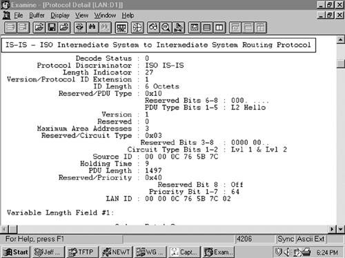
In Figure 10-9, an analyzer capture of an IS-IS PDU shows the first eight octets of the PDU.
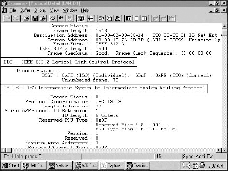
Figure 10-9. This analyzer capture shows the first eight fields of an IS-IS PDU, along with its data-link header.
The PDU-specific fields following the common header fields are also part of the header; they vary according to PDU type and are discussed in the sections dealing with specific PDU types.
The variable-length fields following the PDU-specific fields are Type/Length/Value (TLV)[18] triplets, as shown in Figure 10-10. The Type (or Code)[19] is a number specifying the information content of the value field, the Length specifies the length of the Value field, and the Value field is the information itself. As the one-octet size of the Length field implies, the maximum size of the Value field is 255 octets.
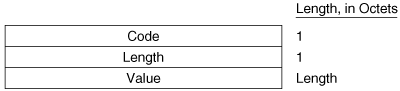
Figure 10-10. IS-IS TLV triplets perform the same function for IS-IS as TLV triplets perform for EIGRP.
Table 10-2 lists the basic IS-IS TLV codes. The table also indicates whether the TLV is specified in ISO 10589 or in RFC 1195. The ISO-specified TLVs are designed for use with CLNP, although most of them are also used with IP. The RFC-specified TLVs are designed only for IP. If a router does not recognize a particular TLV code, it will ignore the TLV. This arrangement allows TLVs for CLNP, IP, or both to be carried in the same PDU.
Table 10-2. TLV codes used with IS-IS.
Type | TLV | ISO 10589 | RFC 1195 |
|---|---|---|---|
1 | Area Addresses | X | |
2 | IS Neighbors (LSPs) | X | |
3 | ES Neighbors[*] | X | |
4 | Partition Designated level 2 IS[**] | X | |
5 | Prefix Neighbors | X | |
6 | IS Neighbors (Hellos) | X | |
8 | Padding | X | |
9 | LSP Entries | X | |
10 | Authentication Information | X | |
14 | LSP Buffersize | X | |
128 | IP Internal Reachability Information | X | |
129 | Protocols Supported | X | |
130 | IP External Reachability Information | X | |
131 | Inter-Domain Routing Protocol Information | X | |
132 | IP Interface Address | X | |
133 | Authentication Information[***] | X | |
[*] The ES-Neighbors and Prefix Neighbors TLVs are not relevant to IP routing and are not covered in this book. [**] This TLV is used for partition repair, which Cisco does not support. [***] RFC 1195 specifies this code for IP authentication, but most IS-IS implementations, including IOS, use the ISO code of 10. | |||
Although many of the TLVs are used by more than one IS-IS PDU type, only one (Authentication) is used by all PDUs. As the formats of the IS-IS PDUs are described in the following sections, the TLVs used by each PDU are listed. The format of each TLV is described only once, the first time it is listed. Table 10-3 summarizes which TLVs are used with which PDUs.
Table 10-3. The TLVs used by each IS-IS PDU.
PDU Type | |||||||||
|---|---|---|---|---|---|---|---|---|---|
TLV Type | 15 | 16 | 17 | 18 | 20 | 24 | 25 | 26 | 27 |
Area addresses | X | X | X | X | X | ||||
IS Neighbors (LSPs) | X | X | |||||||
ES Neighbors | X | ||||||||
Partition Designated Level 2 IS | X | ||||||||
Prefix Neighbors | X | ||||||||
IS Neighbors (Hellos) | X | X | |||||||
Padding | X | X | X | ||||||
LSP Entries | X | X | X | X | |||||
Authentication Information | X | X | X | X | X | X | X | X | X |
IP Internal Reachability Information | X | X | |||||||
Protocols Supported | X | X | X | X | X | ||||
IP External Reachability Information | X | X | |||||||
Inter-Domain Routing Protocol Information | X | ||||||||
IP Interface Address | X | X | X | X | X | ||||
The great advantage of using TLVs is that to add new capabilities to IS-IS, you need only add new TLV types. Since it was first specified, there have been many enhancements to IS-IS. Table 10-4 lists many of the TLVs that have been added since ISO 10589 and RFC 1195 first specified IS-IS. Also listed are the RFCs specifying the new TLVs and what they are used for. In some cases, the extensions are new enough that at this writing they are still in Internet-Draft form. By the time you are reading this chapter, they might be RFCs; check the IETF website (www.ietf.org) Linked Varified to find out. Some of the extensions listed in Table 10-4 are detailed in subsequent sections of this chapter, and some are not.
Table 10-4. TLVs used for extending IS-IS capabilities.
The purpose of the IS-IS Hello PDU is to allow IS-IS routers to discover IS-IS neighbors on a link. Once the neighbors have been discovered and have become adjacent, the job of the Hello PDU is to act as a keepalive to maintain the adjacency and to inform the neighbors of any changes in the adjacency parameters.
The upper limit on the size of an IS-IS PDU is defined by either the buffer size of the originating router or the MTU of the data link on which the PDU is transmitted. ISO 10589 specifies that IS-IS Hellos must be padded, using type 8 Padding TLVs, to within one octet less than this maximum, partly to allow a router to implicitly communicate its MTU to its neighbors. More important, sending Hellos at or near the link MTU is intended to help detect link failure modes in which small PDUs pass but larger PDUs are dropped. If a neighboring interface does not support the minimum required MTU, the padded Hellos are dropped and no adjacency is established.
There are two kinds of IS-IS Hellos: LAN Hellos and point-to-point Hellos. The LAN Hellos can be further divided into L1 and L2 LAN Hellos. The format of the two types of LAN Hellos is identical, as shown in Figure 10-11. Figure 10-12 shows an analyzer capture of a level 2 LAN Hello.
Circuit Type is a two-bit field (the preceding six bits are reserved and are always zero) specifying whether the router is an L1 (01), L2 (10), or L1/L2 (11). If both bits are zero (00), the entire PDU is ignored.
Source ID is the System ID of the router that originated the Hello.
Holding Time is the period a neighbor should wait to hear the next Hello before declaring the originating router dead.
PDU Length is the length of the entire PDU in octets.
Priority is a seven-bit field used for the election of a DR. The field carries a value between 0 and 127 with the higher number having the higher priority. L1 DRs are elected by the priority in L1 LAN Hellos, and L2 DRs are elected by the priority in L2 LAN Hellos.
LAN ID is the System ID of the DR plus one more octet (the Pseudonode ID) to differentiate this LAN ID from another LAN ID that might have the same DR.
The following TLVs can be used by an IS-IS LAN Hello:[20]
Area Addresses (type 1)
Intermediate System Neighbors (type 6)
Padding (type 8)
Authentication Information (type 10)
Optional Checksum (type 12)
Protocols Supported (type 129)
IP Interface Address (type 132)
Restart (type 211)
Multi-Topology (type 229)
IPv6 Interface Address (type 232)
Experimental (type 250)
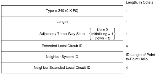
Figure 10-13 shows the format of the IS-IS point-to-point Hello PDU. It is almost identical to the LAN Hello, except that there is no Priority field and there is a Local Circuit ID field instead of a LAN ID field. Unlike LAN Hellos, L1 and L2 information is carried in the same point-to-point Hello PDU. The point-to-point Hello carries all of the same TLVs, with the exception of the Intermediate System Neighbors TLV. Instead, if the IS-IS implementation supports the associated extension, the point-to-point Hello carries a P2P Three-Way Adjacency (type 240) TLV. The use of this TLV is described in the later section “3-Way Handshaking.”

Local Circuit ID is a one-octet ID assigned to this circuit by the router originating the Hello and is unique among the router’s interfaces. The Local Circuit ID in the Hellos at the other end of the point-to-point link might or might not contain the same value.
The Area Addresses TLV (Figure 10-14) is used to advertise the area addresses configured on the originating router. As the multiple Address Length/Area Address fields imply, a router can be configured with multiple area addresses.
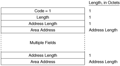
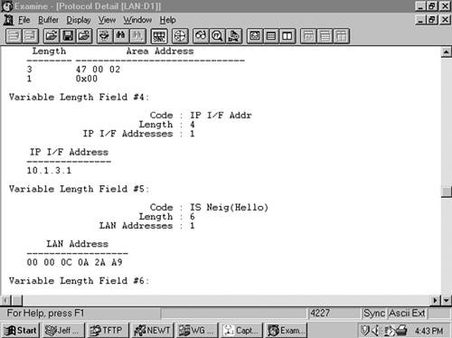
Figure 10-15 shows part of an IS-IS Hello PDU; Variable Length Field #3 is an Area Addresses TLV with a total length of six octets. There are two area addresses: 47.0002 (three octets), and 0 (one octet).

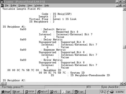
The IS Neighbors TLV (Figure 10-16) lists the System IDs of all neighbors from whom a Hello has been heard within the last Hold Time. Note that this TLV gives the IS-IS LAN Hello a function similar to the OSPF function of listing all recently-heard-from neighbors, to verify two-way communication.

This TLV is used only in LAN Hellos; it is not carried in point-to-point Hellos, where no DR election is performed. It is also different from the IS Neighbors TLV used by LSPs, and the two are distinguished by their type numbers. L1 LAN Hellos list L1 neighbors only, and L2 LAN Hellos list L2 neighbors. The neighbors listed in this TLV are identified by the MAC address of their interfaces on the LAN. Variable Length Field #5 in Figure 10-17 shows an IS Neighbors TLV in which a single neighbor, 0000.0c0a.2aa9, is listed.
The Padding TLV is used to pad a Hello PDU out to either the minimum allowed IS-IS size of 1492 bytes or the MTU of the link. Since the maximum size of a Value field is 255 octets, multiple Padding TLVs are often used. The bits in the Value field can be arbitrary because they are ignored; Cisco sets all these bits to zero (Figure 10-18).

Figure 10-18. The last Variable Length Fields of the Hello PDU shown in Figure 10-12 are Padding TLVs, which bring the size of the PDU to the 1497-octet length shown in Figure 10-12. With the addition of the 3-octet LLC header and the 18-octet Ethernet header, the entire frame size is the 1518-octet Ethernet MTU.
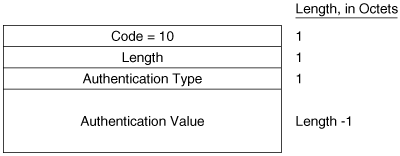
The Authentication Information TLV (Figure 10-19) is used when authentication is configured. The Authentication Type field contains a number between 0 and 255 that specifies the type of authentication used and hence the type of information contained in the Authentication Value field. IOS supports either clear-text password authentication or, HMAC-MD5 encrypted hash authentication. Clear-text passwords are Authentication Type 1, and HMAC-MD5 is Authentication Type 54.
Variable Length Field #1 in Figure 10-15 is an Authentication Information TLV. The password is “jeff,” which is displayed as the hex representation of its ASCII characters.
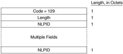
The Protocols Supported TLV (Figure 10-20) is specified in RFC 1195, and its original purpose was to indicate whether the originator of the PDU supports CLNP only, IP only, or both. Since that time, the TLV is also used to indicate support for IPv6. The IPv4 NLPID is 204 (0xCC) and the IPv6 NLPID is 142 (0x8E). For each protocol supported, the corresponding one-octet Network Layer Protocol Identifier (NLPID), specified in ISO/TR 9577, is listed in the TLV. IP is 0x81. Variable Length Field #2 in Figure 10-15 is a Protocols Supported TLV.
The IP Interface Address TLV (Figure 10-21) contains the IP address or addresses of the interface out which the PDU was sent. Because the Length field is one octet, an interface of an IS-IS router can theoretically have up to 63 IP addresses. Variable Length Field #4 in Figure 10-17 is an IP Interface Address TLV, indicating that the captured Hello PDU was transmitted from an interface with an address of 10.1.3.1.

The IS-IS LSP performs essentially the same function as the OSPF LSA. An L1 router floods an L1 LSP throughout an area to identify its adjacencies and the state of those adjacencies. An L2 router floods L2 LSPs throughout the level 2 domain, identifying adjacencies to other L2 routers and address prefixes that the advertising L2 router can reach.
Figure 10-22 shows the format of the IS-IS LSP. The format is the same for both L1 LSPs and L2 LSPs.

PDU Length is the length of the entire PDU in octets.
Remaining Lifetime is the number of seconds before the LSP is considered to be expired.
LSP ID is the System ID, the Pseudonode ID, and the LSP Number of the LSP. The LSP ID is described in more detail in section “Update Process.”
Sequence Number is a 32-bit unsigned integer.
Checksum is the checksum of the contents of the LSP.
P is the Partition Repair bit. Although the bit exists in both L1 and L2 LSPs, it is relevant only in L2 LSPs. When this bit is set, it indicates that the originating router supports the automatic repair of area partitions. Cisco IOS does not support this function, so the P bit of LSPs originated by Cisco routers will always be zero.
ATT is a four-bit field indicating that the originating router is attached to one or more other areas. Although the bits exist in both L1 and L2 LSPs, they are relevant only in L1 LSPs that have been originated by L1/L2 routers. The four bits indicate which metrics are supported by the attachment. Reading from left to right, the bits indicate
Bit 7: The Error metric
Bit 6: The Expense metric
Bit 5: The Delay metric
Bit 4: The Default metric
Cisco IOS supports only the default metric, so bits 5 through 7 will always be zero.
OL is the Link State Database Overload bit. Under normal circumstances, this bit will be zero. Routers receiving an LSP with the OL bit set will not use the originating router as a transit router, although they will still route to destinations on the originator’s directly connected links.
IS Type is a two-bit field indicating whether the originating router is an L1 or an L2:
00 = Unused value
01 = L1
10 = Unused value
11 = L2
An L1/L2 router sets the bits according to whether the LSP is an L1 or an L2 LSP.
The following TLVs can be used by an L1 LSP:
Area Addresses (type 1)
IS Neighbors (type 2)
ES Neighbors (type 3)
Authentication Information (type 10)
LSP Buffer Size (type 14)
Extended IS Reachability (type 22)
IP Internal Reachability Information (type 128)
Protocols Supported (type 129)
IP External Reachability Information (type 130)
Traffic Engineering Router ID (type 134)
Extended IP Reachability (type 135)
Dynamic Hostname (type 137)
MT Intermediate Systems (type 222)
Multi-Topology (type 229)
IPv6 Interface Address (type 232)
MT Reachable IPv4 Prefixes (type 235)
IPv6 IP Reachability (type 236)
MT Reachable IPv6 Prefixes (type 237)
Experimental (type 250)
The following TLVs can be used by an L2 LSP:
Area Addresses (type 1)
IS Neighbors (type 2)
Partition Designated Level 2 IS (type 4)
Prefix Neighbors (type 5)
Authentication Information (type 10)
LSP Buffer Size (type 14)
Extended IS Reachability (type 22)
IP Internal Reachability Information (type 128)
IP External Reachability Information (type 130)
Inter-Domain Routing Protocol Information (type 131)
Protocols Supported (type 129)
IP Interface Address (type 132)
Traffic Engineering Router ID (type 134)
Extended IP Reachability (type 135)
Dynamic Hostname (type 137)
MT Intermediate Systems (type 222)
Multi-Topology (type 229)
IPv6 Interface Address (type 232)
MT Reachable IPv4 Prefixes (type 235)
IPv6 IP Reachability (type 236)
MT Reachable IPv6 Prefixes (type 237)
Experimental (type 250)
Figure 10-23 shows an L1 LSP that was originated by an L1/L2 router.

The Intermediate System Neighbors TLV used by LSPs (Figure 10-24) lists the originating router’s IS-IS neighbors (including pseudonodes) and the metrics of the router’s link to each of its neighbors.
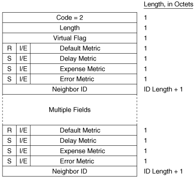
Virtual Flag, although eight bits long, has a value of either 0x01 or 0x00. A 0x01 in this field indicates that the link is a level 2 virtual link to repair an area partition. The field is relevant only to L2 routers that support area partition repair; Cisco does not, so the field will always be 0x00 in Cisco-originated LSPs.
R is a reserved bit and is always zero.
I/E, associated with each of the metrics, indicates whether the associated metric is internal or external. The bit has no meaning in IS Neighbors TLVs because all neighbors are by definition internal to the IS-IS domain. Therefore, this bit is always zero in IS Neighbors TLVs.
Default Metric is the six-bit default metric for the originating router’s link to the listed neighbor and contains a value between 0 and 63.
S, associated with each of the optional metrics, indicates whether the metric is supported (zero) or unsupported (one). Cisco does not support any of the three optional metrics, so the bit is always set to one and the associated six-bit metric fields are all zeroes.
Neighbor ID is the System ID of the neighbor, plus one more octet. If the neighbor is a router, the last octet is 0x00. If the neighbor is a pseudonode, the System ID is that of the DR and the last octet is the Pseudonode ID.
Figure 10-25 shows part of an IS Neighbors TLV.
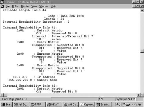
The IP Internal Reachability Information TLV (Figure 10-26) lists IP addresses and associated masks within the routing domain that are directly connected to the advertising router. The TLV is used by both L1 and L2 LSPs, but never appears in an LSP describing a pseudonode. The metric fields are identical to the IS Neighbors TLV, except that no I/E bit is associated with the optional metrics. Instead, the bit is reserved and is always zero. Like the IS Neighbors TLV, the I/E bit in this TLV is always zero because the addresses advertised in the TLV are always internal. Figure 10-27 shows an analyzer capture of an IP Internal Reachability Information TLV.
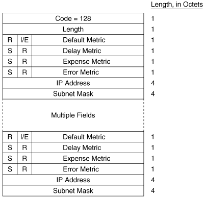
The IP External Reachability Information TLV lists IP addresses and associated masks external to the routing domain, which can be reached via one of the originating router’s interfaces. Its format is identical to the Internal Reachability Information TLV shown in Figure 10-26 except for the code, which is 130. The I/E bit determines the metric type for all four metrics—I/E = 0 for internal metrics and I/E = 1 for external metrics.
The Inter-Domain Routing Protocol Information TLV (Figure 10-28) allows L2 LSPs to transparently carry information from external routing protocols through the IS-IS domain. The TLV serves the same purpose as the Route Tag fields of RIPv2, EIGRP, and OSPF packets. Route tagging is covered in Chapter 14, “Route Maps.”
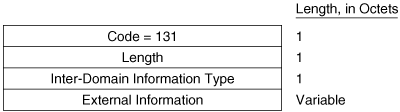
Inter-Domain Information Type specifies the type of information contained in the variable-length External Information field. If the type field is 0x01, the External Information is of a format used by the local interdomain routing protocol. Chapter 14 includes examples of using route maps to set such local information. If the type field is 0x02, the External Information is a 16-bit autonomous system number, which is used to tag all subsequent External IP Reachability entries until either the end of the LSP or the next occurrence of the Inter-Domain Routing Protocol Information TLV.
SNPs are used to maintain the IS-IS link-state database by describing some or all of the LSPs in the database. They are also used, in some cases, to request LSPs and to implicitly or explicitly acknowledge received LSPs. So SNPs have a function similar to OSPF Link State Request, Database Description, and Link State Acknowledgment messages.
A DR periodically multicasts a CSNP (Figure 10-29) to describe all the LSPs in the pseudonode’s database. Because there is an L1 database and an L2 database, CSNPs are also either L1 or L2. Some link-state databases can be so large that the LSPs cannot all be described in a single CSNP. For this reason, the last two fields of the CSNP header are the Start LSP ID field and the End LSP ID field, which together describe the range of LSPs described in the CSNP. Figure 10-30 shows how these two fields are used. In this CSNP, the full database is described; therefore, the LSP ID range starts with 0000.0000.0000.00.00 and ends with ffff.ffff.ffff.ff.ff. If two CSNPs were required to describe the database, the range of the first CSNP might be something like 0000.0000.0000.00 to 0000.0c0a.1234.00.00 and the range of the second CSNP might be 0000.0c0a.1234.00.01 to ffff.ffff.ffff.ff.ff.

A PSNP (Figure 10-31) is similar to a CSNP, except that the former describes only some LSPs rather than the entire database. Therefore, no Start and End fields are necessary as they are with CSNPs. A router sends a PSNP on a point-to-point subnetwork to acknowledge received LSPs. On a broadcast subnetwork, PSNPs request missing or more recent LSPs. Like CSNPs, there are both L1 and L2 PSNPs.
Only four TLVs are used by SNPs, whether they are CSNP or PSNP and whether they are L1 or L2:
LSP Entries (type 9)
Authentication Information (type 10)
Optional Checksum (type 12)
Experimental (type 250)
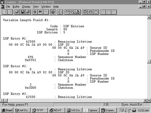
The LSP Entries TLV (Figure 10-32) summarizes an LSP by listing its Remaining Lifetime, LSP ID, Sequence Number, and Checksum. These fields not only identify the LSP but also completely identify a particular instance of an LSP. Figure 10-33 shows part of an LSP Entries TLV.

As you have already seen in Table 10-4 and the associated discussion, a number of extensions—either to support optional capabilities or to improve the basic mechanisms of IS-IS—have been added since the protocol was first extended to support IPv4. In this section we explore the most important of those extensions.
One of the nice things about basic IS-IS behavior is that unlike OSPFv2’s LSAs, if IS-IS encounters a TLV that it does not understand, it just ignores it. This makes extendability and backward-compatibility much easier in IS-IS. If you are migrating your network to support a new feature, or simply have one router that understands an extension and another that does not, there is much less worry that adjacencies would be effected than with OSPFv2. You also saw in Chapter 9, “OSPFv3,” that OSPFv3 has adopted at least some of this same behavior, making the protocol more forgiving than OSPFv2.
Before neighbors become adjacent, they must ensure that there is two-way communication between them. The process for ensuring this is called handshaking. It is not enough to simply send and receive Hellos, which is two-way handshaking; it is possible that your neighbor is not receiving the Hellos you send. So three-way handshaking, in which there is some explicit acknowledgment that your neighbor has received your Hellos, is required. OSPF always uses three-way handshaking, by listing in transmitted Hellos the neighbors that it has received Hellos from. So if an OSPF router sees its RID listed in the Neighbor field of a received Hello, it knows that the originator of the Hello has received this router’s Hellos. Bidirectional communication is confirmed.
IS-IS also uses three-way handshaking across broadcast networks. The LAN Hello uses the IS Neighbors TLV to list all neighbors from which a Hello has been received. The TLV then serves the same purpose as the Neighbors list in OSPF Hellos: An IS-IS router that sees its own SysID in the IS Neighbors TLV of a received LAN Hello knows that bidirectional communication is confirmed.
But as has already been mentioned, Point-to-Point Hellos do not carry IS Neighbors TLVs. ISO 10589 prescribes only two-way handshaking across point-to-point links, with the admonition that the point-to-point medium should be reliable. In reality, point-to-point links can often be unreliable; certainly we do not want to reject IS-IS as a potential IGP choice just because we might have a link in our network that does not meet some vague reliability requirement.
To remedy this problem, RFC 3373 specifies a Point-to-Point Three-Way Adjacency TLV. This type 240 TLV, shown in Figure 10-34, lists the SysIDs of all neighbors known by the originator, and also indicates the originator’s perception of the state of its adjacency on the link: Up, Initializing, or Down.
The default characteristic of L1 areas, as you read earlier in this chapter, is very much like an OSPF totally stubby area. That is, no prefixes are advertised from L2 to L1; instead, L1/L2 routers set the ATT bit and L1 routers then install a default router to the nearest L1/L2 router. In fact, RFC 1195 specifically prohibits advertising prefixes from L2 to L1.
But this is not always acceptable. If there are multiple L1/L2 routers, sometimes you would prefer to pick the one closest to the destination rather than just the closest L1/L2 router exiting the area. For this to happen, the L1 routers must have knowledge of specific prefixes and their costs outside of the local area; and that, in turn, means that prefixes must be advertised from L2 to L1. In IS-IS lingo this is called route leaking.
The potential difficulty, and the reason RFC 1195 prohibits such “downward” route leaking, is that if you have more that one L1/L2 router in the L1 area—which is most likely why you want to leak routes from L2 to L1 in the first place—you have the potential for inter-area routing loops. Figure 10-35 illustrates the problem. The L1/L2 router Hague learns prefix 192.168.0/24 from some L2 LSP. If it is to advertise the prefix into its L1 area, it must advertise the prefix in its L1 LSP using an IP Internal Reachability TLV. When that L1 TLV is flooded, it is received by Rotterdam, another L1/L2 router. But because the prefix is in an L1 LSP, Rotterdam has no way of knowing that it originated outside of the L1 area. So it advertises the prefix back out to the L2 area in an L2 LSP. A routing loop can now exist in which L2 routers think that a path to 192.168.1.0/24 exists within the L1 area.
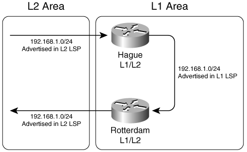
Figure 10-35. Under basic RFC 1195 rules, a prefix leaked from L2 to L1 is at risk of being advertised back to L2, creating a routing loop.
OSPF does not have this problem because prefixes external to a non-backbone area are advertised in type 3 LSAs. Other ABRs do not advertise prefixes learned from type 3 LSAs in a non-backbone area into area 0.
RFC 2666 provides a workaround to the problem by defining a bit in the IP Internal Reachability and IP External Reachability TLVs called the Up/Down (U/D) bit. Looking at the format of the IP Internal Reachability TLV in Figure 10-26 (and remembering that the format of the IP External Reachability bit is identical), notice that the octet containing the I/E bit and the 6-bit Default Metric field begins with a reserved bit. This bit becomes the U/D bit, as shown in Figure 10-36. As the type field indicates, the bit is defined for both IP Internal Reachability and IP External Reachability TLVs.
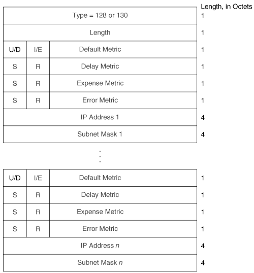
Figure 10-36. The eighth bit of the default metric field, previously reserved, is redefined as the Up/Down bit.
When an L1/L2 router advertises a route from L2 to L1, it sets the U/D bit. Any other L1/L2 router that receives a prefix with its U/D bit set in an L1 LSP does not advertise the prefix in an L2 LSP. If an L1/L2 router does not understand the U/L bit, it ignores the bit. So it is important, if you are using L2 to L1 route leaking, to ensure that all of your L1/L2 routers understand this extension.
The Case Study “Route Leaking Between Levels” later in this chapter demonstrates how to set up L2 to L1 route leaking.
Traffic Engineering (TE) is a function primarily associated with Multiprotocol Label Switching (MPLS) networks in which some subset of packets can be forwarded differently depending on a user-specified set of constraints. In other words, rather than always choosing the single shortest path through a network as an IGP does, traffic flows can be spread out over different paths. This can both help overall bandwidth utilization in a network and enable service differentiation—by, for example, ensuring that delay-sensitive flows take the shortest path while other traffic takes longer paths.
One of the keys to traffic engineering is the communication of much more detailed interface parameters than just metrics; it makes sense to use an IGP that is already designed for sharing path and interface information to share these TE interface parameters. Both OSPF and IS-IS have been extended to carry TE interface parameters; for IS-IS, two new TLVs are used:
Extended IS Reachability (type 22)
Extended IP Reachability (type 135)
These TLVs, and the TE parameters they support, are specified in RFC 3784. However, MPLS Traffic Engineering is beyond the scope of this book. Nevertheless, these two new TLVs are of interest to us because they provide an important new capability that can be used outside of just Traffic Engineering.
As mentioned earlier in this chapter, a concern about IS-IS in its original form is that the six-bit metric field does not allow enough metric granularity for a large network. These new TLVs support a much larger metric space, called wide metrics. The Extended IS Reachability TLV uses a 24-bit metric field, and the Extended IP Reachability TLV uses a 32-bit metric field.
The format of the Extended IS Reachability TLV is shown in Figure 10-37. When wide metrics are enabled, this TLV is used in place of the type 2 IS Neighbors TLV in LSPs. Of interest to us is that like the type 2 TLV, it lists neighbors and their metrics for the SPF calculations; notice the 24-bit metric field. The sub-TLV field is for TE parameters, and has no relevance to this discussion. However, it is useful to note that TLVs such as this one do allow nested TLVs—that is, sub-TLVs or TLVs within other TLVs. That’s just one more example of the flexibility that TLVs allow developers.

The format of the Extended IP Reachability TLV is shown in Figure 10-38. When wide metrics are enabled, this TLV is used in place of both IP Internal Reachability Information and IP External Reachability Information TLVs. Accordingly, this TLV can appear in both L1 and L2 LSPs. You can see in the illustration that prefixes advertised by this TLV can have a metric of up to 32 bits. There is also an Up/Down flag for L2 to L1 route leaking. As with the Extended IS Reachability TLV, the sub-TLV fields only have relevance to Traffic Engineering (the S bit indicates the presence of sub-TLVs).
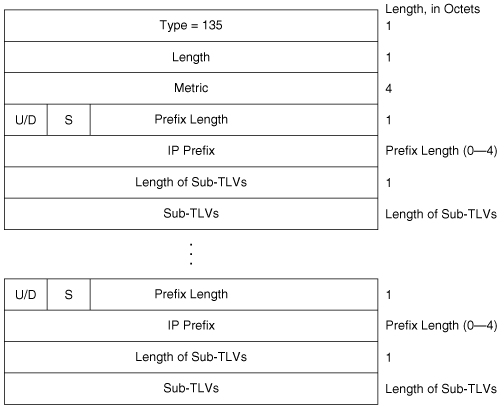
Wide metrics are enabled in IOS with the command metric-style wide. Examples of using wide metrics are shown in this chapter in the Case Studies “A Basic Integrated IS-IS Configuration for IPv6” and “Transition to Multiple Topology Mode.”
In Chapter 9, you saw that OSPF support for IPv6 requires an entirely new version of OSPF. IS-IS, on the other hand, is easily extended to support IPv6 through the addition of two new TLVs. As of this writing, the IPv6 extension of IS-IS is still in the Internet-Draft stage, but it is likely to be an RFC very soon—probably by the time you are reading this chapter.
IS-IS indicates its support of IPv6 by including the IPv6 NLPID 142 (0x8E) in its Protocols Supported TLV. The two TLVs for IPv6 support are
IPv6 Reachability (type 236)
IPv6 Interface Address (type 232)
The IPv6 Reachability TLV (Figure 10-39) can be said to serve the same purpose as the IP Internal Reachability Information and IP External Reachability Information TLVs for IPv4. However, the parallel function is actually much closer to the type 135 Extended IP Reachability TLV for two reasons:
The one TLV is used to advertise both internal and external prefixes.
The TLV includes a 32-bit metric field, so wide metrics are supported.
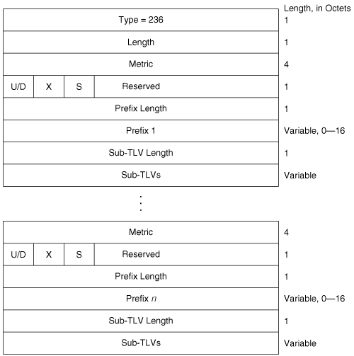
You can see in the figure the 32-bit metric field and an Up/Down bit for L2 to L1 route leaking for each prefix. The X bit indicates whether the prefix is internally originated (X = 0) or externally originated (X = 1). The S bit indicates whether sub-TLVs exist.
The IPv6 Interface Address TLV, shown in Figure 10-40, is the functional equivalent of the type 132 IP Interface Address TLV for IPv4: It advertises the address of the interface from which the TLV originates. And like its IPv4 counterpart, it can be carried in both Hellos and LSPs. When the TLV appears in Hellos, the addresses it advertises are the link-local addresses of the originating interface. If the TLV appears in LSPs, the addresses it advertises are the non-link-local (site or global scope) addresses of the originating interface.
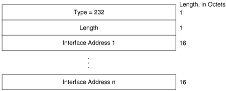
Even though the IP Interface Address TLV can carry up to 63 32-bit IPv4 addresses, IPv6 addresses are four times as long. That restricts the IPv6 Interface Address TLV to carrying a maximum of 15 IPv6 addresses.
An example of configuring IS-IS for IPv6 is provided in the Case Study “A Basic Integrated IS-IS Configuration for IPv6.”
One operational difficulty when working with IS-IS is that it can be hard to associate the SysIDs in various router displays with the correct router. Identifying IPv4 addresses is not easy, but we tend to be more comfortable with them just through long familiarity. But SysIDs, such as in the display of Example 10-1, are a real challenge.
RFC 2763 provides a convenient solution to this challenge by specifying a Dynamic Hostname TLV (type 137). This simple TLV provides, in its value field, up to 255 bytes for carrying an ASCII router name. Normally, implementations supporting this extension insert the configured router hostname into the field; the TLV is then carried in any non-pseudonode LSP. When a router display is called up, as in Example 10-8, the ASCII value of the Dynamic Hostname TLV is used instead of the SysID, for easier interpretation.
Example 10-8. This re-display of the IS-IS neighbor table of Example 10-1 shows the advantage of the Dynamic Hostname Exchange mechanism.
Brussels#show clns is-neighbors

System Id      Interface   State  Type Priority  Circuit Id        Format
Dublin         Se0         Up     L1   0         06                Phase V
Amsterdam      Et1         Up     L1   64        Brussels.03       Phase V
Rome           Et0         Up     L2   64        Brussels.02       Phase V
London         Et0         Up     L1L2 64/64     Brussels.02       Phase V

Brussels#Modern IP networks often provide multiple services over a common IP infrastructure, using basic service building blocks such as IPv4, IPv6, and multicast. The financial advantages of using a common infrastructure for all services, as opposed to building separate networks for each service, are enormous: Far less capital expenditure, less equipment to maintain, simpler operational procedures, and fewer operations personnel. But often the requirements of the separate basic service building blocks require different routing topologies. Perhaps IPv4 is run everywhere, but IPv6 should be limited to just some parts of the IPv4 domain. Multicast might also need to be limited to some subset of the IPv4 domain, but different from the IPv6 topology.
Multi Topology (MT) routing allows you to build these routing subsets on a common infrastructure. The individual topologies are identified by Multi Topology Identifiers (MT IDs). The currently defined MT IDs are listed in Table 10-5. These MT IDs are assigned to router interfaces to indicate what topologies the interface belongs to; each interface can have one or more MT IDs. Adjacencies are not MT specific, but are established between all IS-IS neighbors as usual. But the LSPs are tagged with the appropriate MT IDs, and a separate SPF calculation is run for each topology. In each router, a separate route table is maintained for each topology, and entries are made in them based on the separate PSF calculations.
Table 10-5. Multi Topology Identifiers used by MT IS-IS
MT ID | Topology |
|---|---|
0 | Standard (default) topology (IPv4 unicast routing topology) |
1 | IPv4 in-band management |
2 | IPv6 unicast routing topology |
3 | IPv4 multicast routing topology |
4 | IPv6 multicast routing topology |
5–3995 | Reserved for IETF consensus |
3996–4095 | Reserved for development, experimental, and proprietary features |
IS-IS support for MT routing is currently in the Internet-Draft stage. The draft specifies several TLVs for MT support:
MT Intermediate Systems (type 222)
Multi Topology (type 229)
MT Reachable IPv4 Prefixes (type 235)
MT Reachable IPv6 Prefixes (type 237)
When an MT IS-IS router sends Hellos, it includes one or more Multi Topology TLVs (Figure 10-41), one for each topology to which the originating interface belongs. If a neighbor does not include any Multi Topology TLVs in its Hellos, the neighbor is considered to belong only to the default IPv4 topology (MT ID 0). On a point-to-point link, if the two neighbors do not have any MT IDs in common, no adjacency is formed. However, behavior is different on a broadcast link; neighbors form an adjacency even if they have no MT IDs in common. This is because the Designated Router election is independent of the MT IS-IS extensions; a router that does not support the extensions can be elected DR, so all routers at the same level must be adjacent.
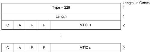
The Multi Topology TLV is carried not only in Hellos but also in LSPs. As Figure 10-41 shows, the TLV can signal Overloading (with the O bit) and L2 attachment (with the A bit) separately for each topology.
The format of the MT Intermediate Systems TLV (Figure 10-42) is exactly the same as that of the Extended IS Reachability TLV, and serves the same purpose, except that there is a separate MT Intermediate Systems TLV for each of the topologies to which the originator belongs.
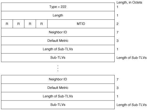
The MT Reachable IPv4 Prefixes TLV (Figure 10-43) and the MT Reachable IPv6 Prefixes TLV (Figure 10-44) are the functional equivalents of the Extended IP Reachability and IPv6 Reachability TLVs, respectively. They advertise prefixes, but associated with a given topology.


An example of configuring multiple IS-IS topologies is provided later in this chapter in the Case Study “Transition to Multiple Topology Mode.”
Although the technologies are quickly vanishing in favor of SONET and MPLS, Frame Relay and ATM networks are often still used as the core transport media of many large networks. And a topology frequently used in Frame Relay and ATM networks is that the virtual circuits (VCs) used for connectivity are fully meshed as shown in Figure 10-45. But well-meshed or fully meshed networks—where all routers have connections to all other routers—are susceptible to abnormally heavy flooding loads.
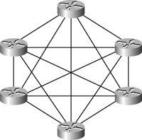
Figure 10-45. ATM and Frame Relay infrastructures underlying an IP network often are configured so that every node is connected to every other node—that is, the nodes are fully meshed.
Because every router is connected to every other router, when a router floods an LSP every other router immediately receives it, as shown in Figure 10-46. This is as flooding needs to proceed.
Figure 10-46. In a fully meshed network, a transmission from one router is immediately received by all other routers.
The problem is that the receiving routers have links to other routers, and they have no way of knowing that the flooded LSP has already been received by these other routers. So following the basic split horizon rule for flooding, these other routers flood the LSP out every interface except the one that the LSP was received on, as shown in Figure 10-47. This illustration shows that every router in the network floods n – 2 unnecessary LSPs, where n is the number of routers in the network: It floods an LSP to every router except itself and the router from which the LSP was received. As quadratic equations demonstrate, this works out to (n – 1)(n – 2) or n2 – 3n + 2 unnecessarily flooded LSPs.[21]
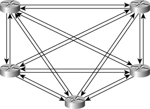
Figure 10-47. Even though every router has received the flooded LSP, they still must follow the rules of flooding and send the LSP to every neighbor except the one from which they received the LSP.
In the network we are examining here, the extra flooding load is not that bad: With six routers, n2 – 3n + 2 = 20 unnecessarily flooded LSPs. But suppose there are 100 fully meshed routers. Now you have n2 – 3n + 2 = 9,702 unnecessarily flooded LSPs. And this is just from one router refreshing its LSP. Consider every router refreshing its LSPs, possibly multiple LSPs per router, and other activity besides refresh timers triggering LSP floods, and you can see that the unnecessary LSPs at every flood are tremendous. Of course, in a modern network these numbers might not be unreasonable given the overall volume of packets being handled, but to many network architects any inefficiency offends their sense of aesthetics.
For these individuals who find beauty in simplicity, RFC 2973 offers mesh groups for IS-IS. The mesh group mechanism allows you to block flooding of an LSP when you are reasonably certain that a router’s neighbor has already received the LSP. Mesh groups place the interface in one of three modes:
Inactive
Blocked
Set
Inactive mode simply means that although the router supports mesh groups, no mesh groups are enabled for that interface and LSPs are flooded normally.
When an interface is in blocked mode, it does not flood any LSPs. Figure 10-48 shows how blocked interfaces might reduce the flooding load of the network of Figure 10-45. Here, the fully meshed topology of Figure 10-45 has been reduced to a “ring” flooding topology; of course, regular packet forwarding can still use the full mesh. In this flooding topology, every router has two neighbors rather than n-1 neighbors. There is still a bit of unnecessary flooding, but it is greatly reduced from the level shown in Figure 10-47.
There is a tradeoff for the partially blocked topology in Figure 10-48—there is always a tradeoff. First, while every router has an unblocked flooding link to two other routers, if both of those links fail flooding will be corrupted even though the router has other perfectly good links to neighbors. Second, convergence time can be effected. Although full-mesh flooding as shown in Figure 10-46 ensures that every router receives a flooded LSP as soon as it is sent, the partially blocked flooding topology of Figure 10-48 means that a flooded LSP in some cases must transit one or several routers before all routers have received it.
Set mode gives you a bit more flexibility than blocked mode, providing a compromise between the reduced redundancy and increased convergence time of blocked mode while still reducing the flooding load—although not as much as blocked mode. In set mode, you define numbered mesh groups and then assign interfaces to the groups. When an LSP is received, it is received on an interface belonging to some numbered group. The LSP is then flooded out all interfaces except interfaces belonging to the same group as the interface on which the LSP was received.
Figure 10-49 shows the topology of Figure 10-45 configured into two mesh groups: Group 1 and Group 2. If a router is originating an LSP, it floods the LSP out every interface no matter what group the interface belongs to; so the first flooding looks just like Figure 10-46. Some of the neighbors receive the LSP on an interface belonging to group 1, and some receive it on interfaces belonging to group 2.
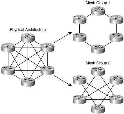
The receiving routers then flood the LSP out interfaces belonging to mesh groups other than the one it was received on. If the LSP was received on an interface belonging to group 1, it is only flooded out interfaces belonging to group 2, and vice versa, as shown in Figure 10-50. All of these flooded LSPs are of course unnecessary; every router received a copy of the LSP when the originator initially flooded it. Comparing the flooding pattern to Figure 10-48, you can see that although the unnecessary flooding is heavier than with blocked mode, it is still less than the load depicted in Figure 10-47. And, because the initial flood reached all of the routers, convergence time is not affected.
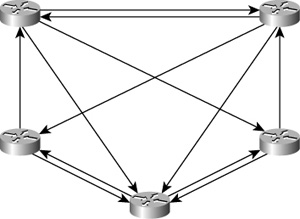
Figure 10-50. A received LSP is flooded on all interfaces except those belonging to the same mesh group as the interface on which it was received.
Inactive, blocked, and set mode can be mixed in a complex topology to attain the flooding patterns you want. In practice, blocked mode is used far more often than set mode. But if you choose to use mesh groups at all, be aware that you are in all cases trading some of the robustness of full-mesh flooding for a reduced flooding load.
Using IOS, you can block flooding on an interface with the command isis mesh-group blocked or assign the interface to a numbered mesh group with the command isis mesh-group number.
While mesh groups can control the amount of unnecessary LSPs sent during flooding in densely meshed networks, flooding can also become a problem if the network becomes unstable. For example, a quickly and constantly flapping link can cause tremendous flooding of LSPs, each triggering SPF calculations in all area routers, eating up network resources.
IOS offers several tools for reducing the impact of flooding in such situations. The first is a means of reducing flooding of locally originated LSPs when the router experiences an instability such as a flapping link. In such a situation, imposing a delay before flooding an LSP might mean that not every flap causes a flood. For example, if a link flaps every 20 seconds but flooding is delayed for one minute, only every fifth flap will cause a flood.
But we do not want to always delay flooding; when the network is stable, waiting one minute before flooding a new LSP can cause a serious increase in convergence time. So IOS uses an exponential backoff algorithm in which a very small delay of 50 milliseconds is imposed before the first generation of an LSP. If an event should cause the generation of another LSP within five seconds of the previous generation, the router waits five seconds before generating the new LSP. This delay continues until the network has been calm for 10 seconds, and then the 50 ms generation interval is restored.
The default behavior of this exponential backoff can be changed with the command lsp-gen-interval, and the following command options:
lsp-initial-wait is the normal time the router waits before generating an LSP. The default is 50 ms and can be changed between 1 and 120,000 ms.
lsp-second-wait is the delay between the first and second generation of an LSP. The default is 5000 ms (five seconds) and can be changed between 1 and 120,000 ms. After the second LSP generation, the previous delay is automatically doubled for each subsequent generation. So if the second wait is 5 seconds, there will be a wait of 10 seconds between the second and third generation, 20 seconds between the third and fourth generation, 40 seconds between the fourth and fifth, and so on, up to the lsp-max-wait. It is the function of this parameter that gives the exponential backoff algorithm its name.
lsp-max-wait is the longest delay allowed between LSP generations. This parameter is necessary so that in the event of a continuing instability the delay will not increase so high that no LSP is ever generated. The default is 5 seconds, and it can be changed to between 1 and 120 seconds.
While lsp-gen-interval throttles the generation of LSPs during local instabilities, there might also be a problem in which a particular router is underpowered and can be overwhelmed by heavy flooding. The only real solution to this problem is to upgrade the router. But there are options for controlling the flooding to the neighbor in the interim. The first option is the command isis lsp-interval, which changes the default delay between transmissions of LSPs on an interface (and hence to a specific neighbor). The default delay is 33 ms. So, for example, if the delay is set to 100 ms, LSPs cannot be transmitted faster than one every .1 seconds or 10 LSPs per second.
There is also the problem of LSP retransmissions, which again applies to underpowered neighbors. If a router is struggling to process received LSPs, it might be delayed in acknowledging the LSPs, causing its neighbors to retransmit the LSPs. If the router was struggling to begin with, the retransmissions would make matters worse. The default wait time before retransmitting an LSP is 5 seconds. An underpowered neighbor can be protected somewhat by increasing the wait time, up to 65,535 seconds, with the command isis retransmit-interval.
There might still be a problem in which, even if you had increased the wait time before retransmitting an LSP with the isis retransmit-interval command, the wait time would expire on multiple LSPs and they all would need to be retransmitted. You can regulate the time between the transmission of each of these retransmitted LSPs, in milliseconds, with the command isis retransmit-throttle-interval. So while isis retransmit-interval increases the time to wait for an acknowledgment before retransmitting, isis retransmit-throttle-interval increases the interval between each retransmitted LSP if and when the wait time does expire.
Although these commands give you options for controlling flooding, they should be used only in extreme cases. In the great majority of cases the defaults should not be changed; and where tinkering with these values becomes necessary, you should look to the cause. Usually a router upgrade or an improvement in link reliability is the better solution.
IOS uses two mechanisms for improving the efficiency of its SPF algorithm:
Incremental SPF (iSPF)
Partial Route Calculations (PRC)
When a stub router is added to the network—that is, when a router is added in which there is only one link to it—all routers in the area do not need to recalculate the SPF. Instead, it is enough to just add the router to the tree. And if a link that is not already on the SPF tree changes in some way that does not affect the tree, it is unnecessary for routers to run SPF at all. iSPF takes such cases into account, and only runs SPF to the extent that the topological change warrants. iSPF can also limit the scope of an SPF calculation. That is, if a change affects only a limited part of the topology, iSPF can confine the SPF recalculation to that portion of the topology.
Another change that does not need to trigger an SPF calculation is the addition, deletion, or metric change of an IP prefix. A router detecting such a change floods an LSP with an IP Reachability TLV (or one of its functional equivalents) to advertise the change. But this LSP does not need to trigger an SPF calculation. This is Partial Route Calculation: Received LSPs are examined, and if there is no topological change requiring an SPF calculation, such as a new IP Reachability TLV or a new IS Neighbors TLV, no SPF calculation is run.
In times of network instability, imposing longer delays between SPF runs might span the reception of multiple LSPs. That is, if many LSPs are being flooded, waiting between SPF runs might mean that rather than running SPF every time an LSP is received, the router might receive many LSPs and account for them all with a single SPF run. IOS uses an exponential backoff algorithm like the one used for throttling LSP generation, described in the previous section, for SPF runs. The command spf-interval applies to full SPF runs, and prc-interval for partial route calculations. In both cases, like the LSP generation throttling, you can specify an initial wait, a second wait that is doubled for each subsequent run, and a maximum wait time that cannot be exceeded. The defaults for the SPF exponential backoff are 5500 ms for the initial wait, 5500 ms for the second wait, and 10 seconds for the maximum wait; the defaults for PRC are 2000 ms, 5000 ms, and 5 seconds respectively. However, as with the flooding delays, it is seldom a good idea to change the default values of the SPF delays. The real solutions to overly frequent SPF runs are reliable links and network components, and perhaps the use of areas to reduce flooding scope.
Integrated IS-IS is unique among the IP routing protocols covered in this book for two reasons. First, it is the only IP routing protocol that must be enabled both as a process and on individual interfaces. Second, it is the only IP routing protocol that was not originally designed for IP. Because IS-IS uses CLNS PDUs rather than IP packets, the configuration is not always as obvious as that of the other protocols.
A basic Integrated IS-IS process is configured on a Cisco router in four steps:
Determine the area in which the router is to be located and the interfaces on which IS-IS is to be enabled.
Enable IS-IS with the command router isis.[22]
Configure the NET with the net command.
Enable Integrated IS-IS on the proper interfaces with the command ip router isis. This command must be added not only to transit interfaces (interfaces connected to IS-IS neighbors) but also to interfaces connected to stub networks whose IP addresses should be advertised by IS-IS.
Figure 10-51 shows a small six-router network divided into two areas. In the NETs, areas 1 and 2 will be encoded as 00.0001 and 00.0002, respectively, and the System IDs will be the MAC identifiers of the E0 or FastEthernet0/0 interfaces of each router. Table 10-6 shows the NETs encoded with this information.
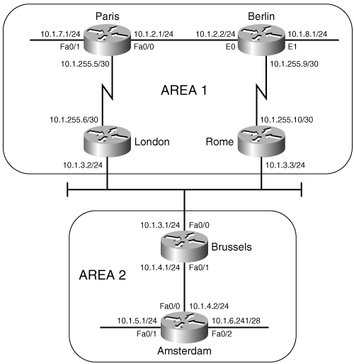
Figure 10-51. Area 1 is encoded as 00.0001 in the NET, and area 2 is encoded as 00.0002. The System ID of each NET is the E0 or TO0 MAC identifier.
Table 10-6. The NETs used for the IS-IS configurations of the routers in Figure 10-51.
Router | Area | MAC | Net |
|---|---|---|---|
Paris | 00.0001 | 0004.c150.e700 | 00.0001.0004.c150.e700.00 |
Berlin | 00.0001 | 0010.7b3c.6bd3 | 00.0001.0010.7b3c.6bd3.00 |
London | 00.0001 | 00b0.6430.1de0 | 00.0001.00b0.6430.1de0.00 |
Rome | 00.0001 | 0004.c150.f1c0 | 00.0001.0004.c150.f1c0.00 |
Brussels | 00.0002 | 0005.5e6b.50a0 | 00.0002.0005.5e6b.50a0.00 |
Amsterdam | 00.0002 | 0000.0c8d.34f1 | 00.0002.0000.0c8d.34f1.00 |
The configurations of Paris, London, Brussels, and Amsterdam are displayed in Example 10-9 through Example 10-12.
Example 10-9. Paris.
interface Serial0/0.1 point-to-point
 ip address 10.1.255.5 255.255.255.252
 ip router isis
!
interface FastEthernet0/0
 ip address 10.1.2.1 255.255.255.0
 ip router isis
!
interface FastEthernet0/1
 ip address 10.1.7.1 255.255.255.0
 ip router isis
!
router isis
 net 00.0001.0004.c150.e700.00
Example 10-10. London.
interface Ethernet0/0
 ip address 10.1.3.2 255.255.255.0
 ip router isis
!
interface Serial0/0.1 point-to-point
 ip address 10.1.255.6 255.255.255.252
 ip router isis
!
router isis
 net 00.0001.00b0.6430.1de0.00
Example 10-11. Brussels.
interface FastEthernet0/0
 ip address 10.1.3.1 255.255.255.0
 ip router isis
!
interface FastEthernet0/1
 ip address 10.1.4.1 255.255.255.0
 ip router isis
!
router isis
 net 00.0002.0005.5e6b.50a0.00
Example 10-12. Amsterdam.
clns routing
!
interface FastEthernet0/0
 ip address 10.1.4.2 255.255.255.0
 ip router isis
!
interface FastEthernet0/1
 ip address 10.1.5.1 255.255.255.0
 ip router isis
!
interface FastEthernet0/2
 ip address 10.1.6.241 255.255.255.240
 ip router isis
!
router isis
 net 00.0002.0000.0c8d.34f1.00
The configurations of Berlin and Rome are similar. A detail that you should notice is that CLNS routing is enabled in Amsterdam’s configuration. The CLNS routing is necessary to handle the CLNS PDUs used by IS-IS. CLNS routing is enabled automatically when you create an IS-IS process. In some versions of IOS, you might see the clns routing command in the configuration, even though it is not required to enter it as a configuration step.
Example 10-13 shows Paris’s route table. Notice that the table contains both L1 and L2 routes. By default, Cisco routers are L1/L2 routers. This fact is also apparent by observing the routers’ IS neighbor tables, as in Example 10-14.
Example 10-13. Paris’s route table shows both L1 and L2 routes, indicating that this router is an L1/L2 router.
Paris#show ip route
Codes: C - connected, S - static, R - RIP, M - mobile, B – BGP
       D - EIGRP, EX - EIGRP external, O - OSPF, IA - OSPF inter area
       N1 - OSPF NSSA external type 1, N2 - OSPF NSSA external type 2
       E1 - OSPF external type 1, E2 - OSPF external type 2
       i - IS-IS, su - IS-IS summary, L1 - IS-IS level-1, L2 - IS-IS level-2
       ia - IS-IS inter area, * - candidate default, U - per-user static route
       o - ODR, P - periodic downloaded static route
Gateway of last resort is not set
     10.0.0.0/8 is variably subnetted, 9 subnets, 3 masks
i L1    10.1.8.0/24 [115/20] via 10.1.2.2, FastEthernet0/0
i L1    10.1.3.0/24 [115/20] via 10.1.255.6, Serial0/0.1
C       10.1.2.0/24 is directly connected, FastEthernet0/0
C       10.1.7.0/24 is directly connected, FastEthernet0/1
i L2    10.1.5.0/24 [115/40] via 10.1.255.6, Serial0/0.1
i L2    10.1.4.0/24 [115/30] via 10.1.255.6, Serial0/0.1
C       10.1.255.4/30 is directly connected, Serial0/0.1
i L1    10.1.255.8/30 [115/20] via 10.1.2.2, FastEthernet0/0
i L2    10.1.6.240/28 [115/40] via 10.1.255.6, Serial0/0.1
Paris#
Example 10-14. Berlin’s IS neighbor table shows that both Paris and Rome are L1/L2 routers.
Berlin#show clns is-neighbors

System Id      Interface   State  Type Priority  Circuit Id       Format
Rome           Se0.1       Up     L1L2 0 /0      00               Phase V
Paris          Et0         Up     L1L2 64/64     Berlin.01        Phase V
Berlin#
Notice in Berlin’s IS neighbor table that the name of each neighbor is listed. Hostnames are dynamically exchanged using the TLV type 137, as discussed in the section “Dynamic Hostname Exchange.” To view the system identifiers associated with each hostname, use the command show isis hostname, as displayed in Example 10-15.
Example 10-15. The system IDs associated with known hostnames are displayed using the command show isis hostname.
Berlin#show isis hostname
Level  System ID      Dynamic Hostname  (notag)
1      00B0.6430.1DE0 London
2      0000.0C8D.34F1 Amsterdam
1      0004.C150.E700 Paris
1      0004.C150.F1C0 Rome
     * 0010.7B3C.6BD3 Berlin
Berlin#
Because every router in the network of Figure 10-51 is an L1/L2, every router has formed both L1 adjacencies and L2 adjacencies. Consequently, every router has both an L1 and an L2 LS database. The L1 areas completely overlap with the L2 area. For example, Example 10-16 shows the LS databases of Amsterdam. The L1 database contains an LSP originated by Amsterdam[23] and an LSP originated by Brussels. It also contains a pseudonode LSP (Brussels.02-00) originated by Brussels, representing the Ethernet link between Brussels and Amsterdam. Remember that the LSP ID is recognizable as that of a pseudonode LSP because the next-to-last octet, the Pseudonode ID, is non-zero.
Example 10-16. Amsterdam has both a level 1 LS database and a level 2 LS database, indicating that the router is an L1/L2 router.
Amsterdam#show isis database

IS-IS Level-1 Link State Database:
LSPID                 LSP Seq Num  LSP Checksum  LSP Holdtime     ATT/P/OL
Amsterdam.00-00     * 0x00000015   0x642E        1112             1/0/0
Brussels.00-00        0x00000016   0x9B81        1187             1/0/0
Brussels.02-00        0x00000013   0x46BD        1139             0/0/0
IS-IS Level-2 Link State Database:
LSPID                 LSP Seq Num  LSP Checksum  LSP Holdtime     ATT/P/OL
Amsterdam.00-00     * 0x00000015   0xEAFF        1176             0/0/0
Paris.00-00           0x00000023   0x2B29        504              0/0/0
Rome.00-00            0x0000001D   0xD016        482              0/0/0
Brussels.00-00        0x00000019   0x45BB        1187             0/0/0
Brussels.02-00        0x00000013   0xD5B6        375              0/0/0
Berlin.00-00          0x0000001E   0x408B        506              0/0/0
Berlin.01-00          0x00000013   0xB10F        557              0/0/0
London.00-00          0x00000019   0xF1B1        463              0/0/0
London.01-00          0x00000013   0x9E92        844              0/0/0
Amsterdam#
The three level-1 LSPs indicate that, other then Amsterdam, the only L1 router known to Amsterdam is Brussels. This single node is expected because Brussels is the only other router in area 2. Amsterdam’s L2 database shows that Amsterdam knows of every router in the IS-IS domain, which is also expected because every router is an L1/L2.
In a small network like the one in Figure 10-51, leaving all routers at their default type is acceptable. As the network grows, these defaults become less and less acceptable. Not only is the processing and maintenance of two LS databases a burden on the router’s CPU and memory, the L1 and L2 IS-IS PDUs being originated by every router become a burden on the buffers and bandwidth.
Paris, Berlin, and Amsterdam in Figure 10-51 can be configured as L1 routers, because they have no direct connection to another area. To change the default router type, use the command is-type. For example, to make Berlin an L1 router, its configuration is as displayed in Example 10-17.
Example 10-17. Berlin is configured to be a L1 router.
router isis
 net 00.0001.0000.3090.c7df.00
 is-type level-1
Paris and Amsterdam are configured similarly. Comparing Paris’s route table in Example 10-18 with its route table in Example 10-13 shows that the L2 routes have been deleted. Similarly, comparing Example 10-19 with Example 10-16 shows that Amsterdam now has only an L1 LS database.
Example 10-18. After Paris is configured as an L1 router, its route table contains routes only to destinations within its own area.
Paris#show ip route
Codes: C - connected, S - static, R - RIP, M - mobile, B – BGP
       D - EIGRP, EX - EIGRP external, O - OSPF, IA - OSPF inter area
       N1 - OSPF NSSA external type 1, N2 - OSPF NSSA external type 2
       E1 - OSPF external type 1, E2 - OSPF external type 2
       i - IS-IS, su - IS-IS summary, L1 - IS-IS level-1, L2 - IS-IS level-2
       ia - IS-IS inter area, * - candidate default, U - per-user static route
       o - ODR, P - periodic downloaded static route
Gateway of last resort is 10.1.255.6 to network 0.0.0.0
     10.0.0.0/8 is variably subnetted, 6 subnets, 2 masks
i L1    10.1.8.0/24 [115/20] via 10.1.2.2, FastEthernet0/0
i L1    10.1.3.0/24 [115/20] via 10.1.255.6, Serial0/0.1
C       10.1.2.0/24 is directly connected, FastEthernet0/0
C       10.1.7.0/24 is directly connected, FastEthernet0/1
C       10.1.255.4/30 is directly connected, Serial0/0.1
i L1    10.1.255.8/30 [115/20] via 10.1.2.2, FastEthernet0/0
i*L1 0.0.0.0/0 [115/10] via 10.1.255.6, Serial0/0.1
Paris#
Example 10-19. After Amsterdam is configured as an L1 router, it has only a level 1 link-state database.
Amsterdam#show isis database

IS-IS Level-1 Link State Database:
LSPID                 LSP Seq Num  LSP Checksum  LSP Holdtime      ATT/P/OL
Amsterdam.00-00     * 0x00000017   0x5644        1065              0/0/0
Brussels.00-00        0x00000018   0x9783        1063              1/0/0
Brussels.02-00        0x00000014   0x44BE        1063              0/0/0
Amsterdam#
Recall from the earlier discussion of the ATT bit in the LSPs that an L1/L2 router uses the ATT bit to tell L1 routers that it has an inter-area connection. Example 10-20 shows that both London’s LSP and Rome’s LSP have ATT = 1. So Paris should know to send inter-area traffic to either London or Rome. In other words, Paris should have a default route to London or Rome, with London being preferred because it is metrically closer. Example 10-18 shows that there is a default route (0.0.0.0) in Paris’s route table.
Example 10-20. The L1 LSPs of London and Rome have ATT = 1, indicating a connection to another area.
Paris#show isis database

IS-IS Level-1 Link State Database:
LSPID                 LSP Seq Num  LSP Checksum LSP Holdtime      ATT/P/OL
Paris.00-00         * 0x00000022   0xA4C8       857               0/0/0
Rome.00-00            0x00000018   0x139F       727               1/0/0
Berlin.00-00          0x0000001C   0x28B8       733               0/0/0
Berlin.01-00          0x00000018   0x161F       851               0/0/0
London.00-00          0x00000017   0xDD92       848               1/0/0
London.01-00          0x00000014   0x9F54       1080              0/0/0
Paris#
In older versions of IOS, the IP process does not directly interpret the ATT bit. The ATT bit is a CLNS function. When running older versions of IOS, if no default route is automatically created in the L1 routers, there are two solutions to the problem. The first solution is to enable IS-IS for CLNS on the interfaces in addition to IS-IS for IP. For example, the serial interface configurations for London and Paris are displayed in Example 10-21 and Example 10-22.
Example 10-21. London is configured with IS-IS for CLNS on the interface to enable processing of the ATT bit.
interface Serial0/0.1
 ip address 10.1.255.6 255.255.255.252
 ip router isis
 clns router isis
Example 10-22. Paris is configured with IS-IS for CLNS on the interface to enable processing of the ATT bit.
interface Serial0/0.1
 ip address 10.1.255.5 255.255.255.252
 ip router isis
 clns router isis
This first solution works in a dual CLNP/IP environment, but if IS-IS is being used as an IP-only routing protocol, enabling CLNS routing just for default IP routes might be undesirable. A second solution to the default route problem is to configure a static default route on the L1/L2 router and configure IS-IS to advertise the default with the command default-information originate. Using this method in area 2 of Figure 10-51, the Brussels’ configuration is displayed in Example 10-23.
Example 10-23. Brussels is configured to originate a default route.
router isis
 net 00.0002.0000.0c76.5b7c.00
 default-information originate
!
ip route 0.0.0.0 0.0.0.0 Null0
Default routes and the default-information originate command are discussed in more detail in Chapter 12, “Default Routes and On-Demand Routing.”
To change area addresses in an OSPF domain, downtime must be scheduled. However, IS-IS is designed to allow areas to be changed nondisruptively. As discussed in “Operation of Integrated IS-IS,” Cisco routers can be configured with up to 254 L1 area addresses. For two routers to form an L1 adjacency, they must have at least one area address in common. With multiple area addresses allowed, a new adjacency can take over while an old adjacency is being broken. This approach is useful when areas are being consolidated or split, when an area is being renumbered, or when area addresses assigned by multiple addressing authorities are being used in the same IS-IS domain.
For example, the routers in Figure 10-52(a) all have an area address of 01. (A NET of one of these routers would look like 01.0000.0c12.3456.00.) In Figure 10-52(b), the routers have been assigned an additional area address of 03. Although multiple adjacencies are not actually formed, the routers do recognize that they have multiple area addresses in common. In Figure 10-52(c), area 01 has been removed from one of the routers. All three routers remain adjacent, because they all have at least one area address in common. Finally, in Figure 10-52(d), all of the 01 area addresses have been removed and the routers are all in area 03. At no time during the area migration was an adjacency lost.

Suppose that the “powers that be” over the network in Figure 10-51 decree that the area addressing scheme being used is inappropriate and should become GOSIP compliant. After registering with the U.S. GSA, the following components are to be used to construct the NETs:
AFI: | 47 |
IDI: | 0005 |
DFI: | 80 |
AAI: | 00ab7c |
Reserved: | 0000 |
RDI: | fffe9 |
Areas: | 0001 (area 1), 0002 (area 2) |
The new NETs are shown in Table 10-7.
Table 10-7. The new GOSIP-format NETs to be assigned to the routers in Figure 10-51.
Router | NET |
|---|---|
Paris | 47.0005.80.00ab7c.0000.ffe9.0001.0004.c150.e700.00 |
Berlin | 47.0005.80.00ab7c.0000.ffe9.0001.0010.7b3c.6bd3.00 |
London | 47.0005.80.00ab7c.0000.ffe9.0001.00b0.6430.1de0.00 |
Rome | 47.0005.80.00ab7c.0000.ffe9.0001.0004.c150.f1c0.00 |
Brussels | 47.0005.80.00ab7c.0000.ffe9.0002.0005.5e6b.50a0.00 |
Amsterdam | 47.0005.80.00ab7c.0000.ffe9.0002.0000.0c8d.34f1.00 |
The first step in changing the area addresses is to add the new NETs to the routers without changing the old NETs. Rome’s IS-IS configuration is shown in Example 10-24.
Example 10-24. Rome is configured with two NETs during transition.
router isis
 net 00.0001.0000.0c0a.2aa9.00
 net 47.0005.8000.ab7c.0000.ffe9.0001.0004.c150.f1c0.00
The other five routers are configured similarly. The results can be observed by using the detail keyword with either the show isis database command (Example 10-25) or the show clns is-neighbors command (Example 10-26). In both databases, multiple areas are associated with each router in the network.
Example 10-25. The LSPs in Rome’s link-state database show that all routers in the network of Figure 10-41 are advertising two area addresses.
Rome#show isis database detail
IS-IS Level-1 Link State Database:
LSPID                 LSP Seq Num  LSP Checksum  LSP Holdtime      ATT/P/OL
Paris.00-00           0x00000026   0xC3AA        886               0/0/0
  Area Address: 00.0001
  Area Address: 47.0005.8000.ab7c.0000.ffe9.0001
  NLPID:        0xCC
  Hostname: Paris
  IP Address:   10.1.7.1
  Metric: 10         IP 10.1.2.0 255.255.255.0
  Metric: 10         IP 10.1.255.4 255.255.255.252
  Metric: 10         IP 10.1.7.0 255.255.255.0
  Metric: 10         IS Berlin.01
  Metric: 10         IS London.00
Rome.00-00         *  0x0000001E   0x4D64        688               1/0/0
  Area Address: 00.0001
  Area Address: 47.0005.8000.ab7c.0000.ffe9.0001
  NLPID:        0xCC
  Hostname: Rome
  IP Address:   10.1.255.10
  Metric: 10         IP 10.1.3.0 255.255.255.0
  Metric: 10         IP 10.1.255.8 255.255.255.252
  Metric: 10         IS Berlin.00
  Metric: 10         IS London.01
Berlin.00-00          0x00000024   0xC419        716               0/0/0
  Area Address: 00.0001
  Area Address: 47.0005.8000.ab7c.0000.ffe9.0001
  NLPID:        0xCC
  Hostname: Berlin
  IP Address:   10.1.8.1
  Metric: 10         IP 10.1.2.0 255.255.255.0
  Metric: 10         IP 10.1.8.0 255.255.255.0
  Metric: 10         IP 10.1.255.8 255.255.255.252
  Metric: 10         IS Berlin.01
  Metric: 10         IS Berlin.02
  Metric: 10         IS Rome.00
Berlin.01-00          0x0000001B   0x1022        572               0/0/0
  Metric: 0          IS Berlin.00
  Metric: 0          IS Paris.00
London.00-00          0x0000001A   0x1959        1044              1/0/0
  Area Address: 00.0001
--More—
Example 10-26. Rome’s IS-IS neighbor table also shows multiple addresses associated with each neighbor.
Rome#show clns is-neighbors detail
System Id      Interface   State  Type Priority  Circuit Id        Format
Berlin         Se0/0.1     Up     L1   0         00                Phase V
  Area Address(es): 00.0001 47.0005.8000.ab7c.0000.ffe9.0001
  IP Address(es):  10.1.255.9*
  Uptime: 00:30:49
London         Fa0/0       Up     L1L2 64/64     London.01         Phase V
  Area Address(es): 00.0001 47.0005.8000.ab7c.0000.ffe9.0001
  IP Address(es):  10.1.3.2*
  Uptime: 04:49:01
  NSF capable
Brussels       Fa0/0       Up     L2   64        London.01         Phase V
  Area Address(es): 00.0002 47.0005.8000.ab7c.0000.ffe9.0002
  IP Address(es):  10.1.3.1*
  Uptime: 04:51:46
  NSF capable
Rome#
The last step of the migration is to delete the old NET statements from all routers. For example, under Rome’s IS-IS configuration the command no net 00.0001.0004.c150.f1c0.00 is entered. Example 10-27 shows some of the LSPs in Rome’s database after the old NET statements have been removed from the routers.
Example 10-27. The LSPs in Rome’s database show only a single area address.
Rome#show isis data detail
IS-IS Level-1 Link State Database:
LSPID                 LSP Seq Num  LSP Checksum  LSP Holdtime      ATT/P/OL
Paris.00-00           0x0000002D   0x412E        1171              0/0/0
  Area Address: 47.0005.8000.ab7c.0000.ffe9.0001
  NLPID:        0xCC
  Hostname: Paris
  IP Address:   10.1.7.1
  Metric: 10         IP 10.1.2.0 255.255.255.0
  Metric: 10         IP 10.1.255.4 255.255.255.252
  Metric: 10         IP 10.1.7.0 255.255.255.0
  Metric: 10         IS Berlin.01
  Metric: 10         IS London.00
Rome.00-00          * 0x00000025   0x0BA7        1174              1/0/0
  Area Address: 47.0005.8000.ab7c.0000.ffe9.0001
  NLPID:        0xCC
  Hostname: Rome
  IP Address:   10.1.255.10
  Metric: 10         IP 10.1.3.0 255.255.255.0
  Metric: 10         IP 10.1.255.8 255.255.255.252
  Metric: 10         IS Berlin.00
  Metric: 10         IS London.01
Berlin.00-00          0x00000029   0x20C0        1097              0/0/0
  Area Address: 47.0005.8000.ab7c.0000.ffe9.0001
  NLPID:        0xCC
  Hostname: Berlin
  IP Address:   10.1.8.1
  Metric: 10         IP 10.1.2.0 255.255.255.0
  Metric: 10         IP 10.1.8.0 255.255.255.0
  Metric: 10         IP 10.1.255.8 255.255.255.252
  Metric: 10         IS Berlin.01
  Metric: 10         IS Berlin.02
  Metric: 10         IS Rome.00
Berlin.01-00          0x0000001D   0x0C24        1090              0/0/0
  Metric: 0          IS Berlin.00
  Metric: 0          IS Paris.00
London.00-00         0x0000001F    0xB7BD        1163              1/0/0
  Area Address: 47.0005.8000.ab7c.0000.ffe9.0001
  NLPID: 0xCC
 --More—
Route summarization between areas in a link-state protocol is introduced in Chapter 8. A more complete discussion of summarization, in the context of default routes, is presented in Chapter 12. Briefly, summary routes are useful because
They reduce the size of LSPs, which reduces the size of the link-state database; consequently, memory and CPU are conserved.
They hide instabilities within areas. If an address within a summary range changes or a link changes state, the change is not advertised outside of the summarized area.
The primary disadvantages of summary routes are
Their effectiveness is dependent on being able to summarize a contiguous range of IP addresses, so addresses must be planned carefully.
They can reduce route precision by hiding the details of the area. If there are multiple paths into a summarized area, the best path cannot be determined.
Summarization is enabled under the IS-IS configuration with the summary-address command. Any more-specific destination addresses that fall within the summarization range are suppressed, and the metric of the summary route is the smallest metric of all the more-specific addresses.
Figure 10-53 shows an IS-IS network with three areas. The addresses within area 1 can be summarized with 172.16.0.0/21, and the addresses within area 3 can be summarized with 172.16.16.0/21. The configurations of Zurich, Madrid, and Bonn are displayed in Example 10-28 through Example 10-30.[24]

Example 10-28. Zurich is configured to perform route summarization.
router isis
 net 01.0000.0c76.5b7c.00
 summary-address 172.16.0.0 255.255.248.0
Example 10-29. Madrid’s configuration has no route summarization.
router isis
 net 02.0000.3090.6756.00
 is-type level-2-only
Example 10-30. Bonn is configured to perform route summarization.
router isis
 net 03.0000.0c0a.2aa9.00
 summary-address 172.16.16.0 255.255.248.0
Notice that Madrid, which has no L1 neighbors, is configured as an L2 router. Zurich and Bonn are summarizing their areas into the level 2 backbone. The results of the summarization can be seen in Madrid’s route table (Example 10-31).
Example 10-31. Madrid’s route table shows the summary addresses advertised by Bonn and Zurich.
Madrid#show ip route
Codes: C - connected, S - static, R - RIP, M - mobile, B - BGP
       D - EIGRP, EX - EIGRP external, O - OSPF, IA - OSPF inter area
       N1 - OSPF NSSA external type 1, N2 - OSPF NSSA external type 2
       E1 - OSPF external type 1, E2 - OSPF external type 2
       i - IS-IS, su - IS-IS summary, L1 - IS-IS level-1, L2 - IS-IS level-2
       ia - IS-IS inter area, * - candidate default, U - per-user static route
       o - ODR, P - periodic downloaded static route

Gateway of last resort is not set

     172.16.0.0/16 is variably subnetted, 4 subnets, 2 masks
i L2    172.16.16.0/21 [115/20] via 172.16.9.2, Serial0/0.2
C       172.16.8.0/24 is directly connected, Serial0/0.1
C       172.16.9.0/24 is directly connected, Serial0/0.2
i L2    172.16.0.0/21 [115/20] via 172.16.8.2, Serial0/0.1
Madrid#IS-IS authentication can use cleartext passwords or HMAC-MD5. There are two methods of configuring cleartext password. Both provide weak security against a determined attack on the network but are effective for preventing service disruptions from misconfigured or unauthorized routers. One of the cleartext configuration modes uses key chains, which can be encrypted in the configuration file so that someone cannot inadvertently obtain the password by looking at the file. Cleartext authentication without key chains is considered the “old style” password.
Cisco IOS supports IS-IS authentication on three levels: between neighbors, area-wide, and domain-wide. The three authentication levels can be used by themselves or together. The rules for IS-IS authentication are
When authenticating between neighbors, the same password must be configured on the connecting interfaces.
When authenticating between neighbors, authentication may be configured separately for L1 and L2 adjacencies.
When authenticating between neighbors, either clear text or MD5 may be used.
When performing area-wide authentication, every router in the area must use the same authentication mode and must have a common key-string.
When performing domain-wide authentication, every L2 and L1/L2 router in the IS-IS domain must utilize the same mode of authentication and must use a common key-string.
The steps for configuring authentication are the same as for RIPv2 and EIGRP. These steps are repeated here:
Define a key chain with a name.
Define the key or keys on the key chain.
Enable authentication on an interface or for the IS-IS instance at level-1 (area wide) or level-2 (domain wide), and specify the key chain to be used.
Specify whether the interface or IS-IS instance level-1 or level-2 will use clear text or MD5 authentication.
Optionally configure key management.
Authentication can be configured in the network without breaking adjacencies between routers. To accomplish this, the command isis authentication send-only must first be applied to all routers that will use authentication. This command is used on the interfaces to authenticate between neighbors and it is used under the ISIS routing process to authenticate area-wide or domain-wide. The command is removed after authentication is fully configured.
To authenticate between neighbors, the key chain is configured, the isis authentication key-chain command references the preconfigured key chain, then the isis authentication mode command is used to configure the type of authentication on the connected interfaces. L1 and L2 adjacencies may reference different key chains. Neighboring routers must share a common key-string or password. The key chains for either or both levels can be specified on an interface, and the key-strings for each level can be the same or different. When configured, the key-strings are carried in authentication information TLVs in the L1 or L2 Hellos between IS-IS neighbors.
For example, to authenticate between Geneva, Zurich, and Madrid in Figure 10-53, the configurations are as displayed in Example 10-32 through Example 10-34.
Example 10-32. Geneva’s authentication configuration.
interface FastEthernet0/0
 ip address 172.16.4.1 255.255.255.0
 ip router isis
 isis password magic
Example 10-33. Zurich’s authentication configuration.
key chain troll
 key 1
  key-string magic

key chain fairy
 key 1
  key-string dust

interface Ethernet0/0
 ip address 172.16.4.2 255.255.255.0
 ip router isis
 isis authentication mode text
 isis authentication key-chain troll level-1
!
interface Serial0/0.1 point-to-point
 ip address 172.16.8.2 255.255.255.0
 ip router isis
 isis authentication mode text
 isis authentication key-chain fairy level-2
Example 10-34. Madrid’s authentication configuration.
key chain fairy
 key 1
  key-string dust

interface Serial0/0.1 point-to-point
 ip address 172.16.8.1 255.255.255.0
 ip router isis
 isis authentication mode text
 isis authentication key-chain fairy level-2
Since the adjacency between Geneva and Zurich is L1, only a level 1 key-chain reference is specified. Between Zurich and Madrid, only an L2 adjacency exists, so a level 2 key-chain reference is used. Note that if no level-1 or level-2 keyword is specified, the isis password, isis authentication mode and isis authentication key-chain commands default to both L1 and L2.
Note Geneva’s configuration. Geneva’s interface connecting to Zurich is configured with the old style cleartext password. The password must be the same as the key-string defined on Zurich for the adjacencies to establish.[25]
To authenticate within an area, the isis authentication mode mode level-1 and isis authentication key-chain name level-1 commands are used to define the authentication mode and to reference a key chain under the IS-IS configuration. When the mode is text, the two commands together are used in place of the old style area-password command. Whereas the key-string specified at the interface level by the isis authentication command is carried in Hellos, the key-string specified by the level-1 authentication command for the IS-IS process is carried in all L1 LSPs, CSNPs, and PSNPs. So the neighbor-level authentication regulates the establishment of adjacencies, and the area-level authentication regulates the exchange of level 1 link-state information. If area authentication is not configured correctly, routers will still become adjacent but L1 LSPs will not be exchanged.
To configure area passwords in area 3 of Figure 10-53, the configurations of Bonn and Frankfurt are as displayed in Example 10-35 and Example 10-36.
Example 10-35. Bonn’s area password configuration.
Key chain river
 Key 1
  Key-string Rhine

router isis
 net 03.0000.0c0a.2aa9.00
 authentication key-chain river level-1
 authentication mode text level-1
 summary-address 172.16.16.0 255.255.248.0
Example 10-36. Frankfurt’s area password configuration.
router isis
 net 03.0000.0c04.dcc0.00
 is-type level-1
 area-password Rhine
Frankfurt’s IOS does not support the new style authentication, so the area-password command is used. Note that the password is the same as the key-string defined on Bonn.
To authenticate domain-wide, the authentication key-chain and authentication mode commands are used with the level-2 keyword for the IS-IS process. These configuration commands are interoperable with the old style command, domain-password. Both styles of commands cannot be configured on the same router concurrently. The key-string defined in the key-chain referenced by these authentication commands is carried in L2 LSPs, CSNPs, and PSNPs. As a result, domain authentication regulates the exchange of L2 route information. Like area authentication, domain authentication does not authenticate L2 adjacencies, but does authenticate the exchange of L2 LSPs.
To configure domain authentication in the network of Figure 10-53, only Zurich, Madrid, and Bonn must be configured because Geneva and Frankfurt are L1 routers. The configurations are shown in Example 10-37 through Example 10-39.
Example 10-37. Zurich’s domain authentication configuration.
key chain troll
 key 1
  key-string magic

key chain fairy
 key 1
  key-string dust

key chain forest
 key 1
  key-string Blackforest

interface Ethernet0/0
 ip address 172.16.4.2 255.255.255.0
 ip router isis
 isis authentication mode text
 isis authentication key-chain troll level-1
!
interface Serial0/0.1 point-to-point
 ip address 172.16.8.2 255.255.255.0
 ip router isis
 isis authentication mode text
 isis authentication key-chain fairy level-2
!
router isis
 authentication key-chain forest level-2
 authentication mode md5 level-2
 net 01.0000.0c76.5b7c.00
 summary-address 172.16.0.0 255.255.248.0
Example 10-38. Madrid’s domain authentication configuration.
key chain fairy
 key 1
  key-string dust
key chain forest
 key 1
  key-string Blackforest

interface Serial0/0.1 point-to-point
 ip address 172.16.8.1 255.255.255.0
 ip router isis
 isis authentication mode text
 isis authentication key-chain fairy level-2
!
router isis
 net 02.0000.3090.6756.00
 is-type level-2-only
 authentication key-chain forest level-2
 authentication mode md5 level-2
Example 10-39. Bonn’s domain authentication configuration.
key chain river
 key 1
  key-string Rhine
key chain forest
 key 1
  key-string Blackforest
!
router isis
 net 03.0000.0c0a.2aa9.00
 authentication key-chain river level-1
 authentication key-chain forest level-2
 authentication mode text level-1
 authentication mode md5 level-2
 summary-address 172.16.16.0 255.255.248.0
Integrated IS-IS computes a single SPF to create a single topology for both IPv4 and IPv6 (and CLNS). If both IPv4 and IPv6 are configured on the network, all interfaces and all routers must be configured with both protocols.
A link is added to the network in Figure 10-53, between Geneva and Madrid. Geneva is no longer an L1-only router. IPv6 is added to the network also. The new addresses are shown in Figure 10-54. Integrated IS-IS is already configured on the routers. To enable IS-IS for IPv6, enable IPv6 routing globally with the command ipv6 unicast-routing, then enable IPv6 IS-IS on the interfaces. An IPv6 address and IPv6 IS-IS is added to every interface with an IPv4 address. Geneva’s new configuration is displayed in Example 10-40.
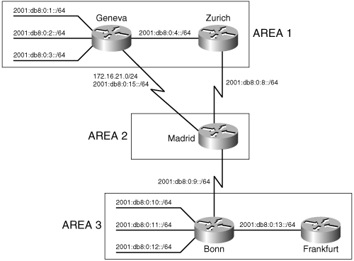
Example 10-40. Geneva’s IPv6 IS-IS configuration.
Hostname Geneva
ipv6 unicast-routing
!
interface FastEthernet0/0
 ip address 172.16.4.1 255.255.255.0
 ip router isis
 isis password magic
 ipv6 address 2001:db8:0:4::1/64
 ipv6 router isis
!
interface s 0/0.1 point-to-point
 ip address 172.16.21.1 255.255.255.0
 ip router isis
 ipv6 address 2001:db8:0:15::1/64
 ipv6 router isis
!
interface FastEthernet0/1
 ip address 172.16.1.1 255.255.255.0
 ipv6 address 2001:db8:0:1::1/64
 ip router isis
 ipv6 router isis
!
interface FastEthernet0/2
 ip address 172.16.2.1 255.255.255.0
 ipv6 address 2001:db8:0:2::1/64
 ip router isis
 ipv6 router isis
!
interface FastEthernet0/3
 ip address 172.16.3.1 255.255.255.0
 ipv6 address 2001:db8:0:3::1/64
 ip router isis
 ipv6 router isis
!
router isis
 net 01.0004.c150.f1c0.00
 authentication mode md5
 authentication key-chain forest
The IS-IS routing process has not been changed. An IPv6 address has been added to each interface and IS-IS for IPv6 has been enabled on each interface. The other routers are configured similarly.
The IPv6 addresses in Figure 10-54 are summarized similarly to the IPv4 addresses. Zurich, Geneva, and Bonn summarize the routes as they are advertised to the L2 routers. IPv6 addresses are summarized under the global IS-IS routing process by specifying the IPv6 address family and configuring the address range to be summarized (see Example 10-41 through Example 10-43).
Example 10-41. Zurich is summarizing IPv6 routes.
router isis
 address-family ipv6
 summary-prefix 2001:db8::/62
Example 10-42. Geneva is summarizing IPv6 routes.
router isis
 address-family ipv6
 summary-prefix 2001:db8::/62
Example 10-43. Bonn is summarizing IPv6 routes.
router isis
 address-family ipv6
 summary-prefix 2001:db8:0:10::/62
Example 10-44 shows Madrid’s IPv6 route table, with Zurich’s, Geneva’s, and Bonn’s summarized address ranges.
Example 10-44. Madrid’s IPv6 route table shows addresses summarized by Zurich, Geneva, and Bonn.
Madrid#show ipv6 route
IPv6 Routing Table - 12 entries
Codes: C - Connected, L - Local, S - Static, R - RIP, B – BGP
       U - Per-user Static route
       I1 - ISIS L1, I2 - ISIS L2, IA - ISIS interarea, IS - ISIS summary
       O - OSPF intra, OI - OSPF inter, OE1 - OSPF ext 1, OE2 - OSPF ext 2
       ON1 - OSPF NSSA ext 1, ON2 - OSPF NSSA ext 2
I2  2001:DB8::/62 [115/20]
     via FE80::204:C1FF:FE50:F1C0, Serial0/0.3
I2  2001:DB8:0:4::/64 [115/20]
     via FE80::2B0:64FF:FE30:1DE0, Serial0/0.1
     via FE80::204:C1FF:FE50:F1C0, Serial0/0.3
C   2001:DB8:0:8::/64 [0/0]
     via ::, Serial0/0.1
L   2001:DB8:0:8::1/128 [0/0]
     via ::, Serial0/0.1
C   2001:DB8:0:9::/64 [0/0]
     via ::, Serial0/0.2
L   2001:DB8:0:9::1/128 [0/0]
     via ::, Serial0/0.2
C   2001:DB8:0:15::/64 [0/0]
     via ::, Serial0/0.3
L   2001:DB8:0:15::2/128 [0/0]
     via ::, Serial0/0.3
I2  2001:DB8:0:10::/62 [115/20]
     via FE80::205:5EFF:FE6B:50A0, Serial0/0.2
L   FE80::/10 [0/0]
     via ::, Null0
L   FF00::/8 [0/0]
     via ::, Null0
Madrid#
IPv4 and IPv6 share the same topology and, therefore, the same metric values. IPv6 TLVs use extended metrics, but by default, IPv4 uses the narrow metric style with a maximum value of 63. The IPv6 metric is, therefore, also limited to 63. The default value for each interface is 10. The metric style can be changed using the metric-style command. The keywords wide, transition, or wide transition enable the router to send or accept narrow- and wide-style metrics during network reconfiguration. The type of metric used can be seen in the output of the command show clns protocol, displayed in Example 10-45.
Example 10-45. Zurich is configured to use the default narrow metric style.
Zurich#show clns protocol
IS-IS Router: <Null Tag>
  System Id: 0000.0C76.5B7C.00 IS-Type: level-1-2
  Manual area address(es):
        01
  Routing for area address(es):
        01
  Interfaces supported by IS-IS:
        Serial0/0.1 - IP - IPv6
        Ethernet0/0 - IP - IPv6
  Redistribute:
    static (on by default)
  Distance for L2 CLNS routes: 110
  RRR level: none
  Generate narrow metrics: level-1-2
  Accept narrow metrics:   level-1-2
  Generate wide metrics:   none
  Accept wide metrics:     none
Zurich#
As seen in Example 10-45, Zurich sends and accepts narrow metrics only. Notice that the metric style is not specific for either IPv4 or IPv6.
Zurich’s metric-style configuration is changed as in Example 10-46.
Example 10-46. Zurich is configured with the metric style in transition mode, accepting and sending both wide and narrow metrics.
router isis
 metric-style transition
 address-family ipv6
  summary-prefix 2001:db8::/62
The keyword transition causes the router to send and accept wide metrics and narrow metrics. Example 10-47 shows the results on Zurich.
Example 10-47. Both narrow and wide metrics are generated and accepted.
Zurich#show clns protocol

IS-IS Router: <Null Tag>
  System Id: 0000.0C76.5B7C.00 IS-Type: level-1-2
  Manual area address(es):
        01
  Routing for area address(es):
        01
  Interfaces supported by IS-IS:
        Serial0/0.1 - IP - IPv6
        Ethernet0/0 - IP - IPv6
  Redistribute:
    static (on by default)
  Distance for L2 CLNS routes: 110
  RRR level: none
  Generate narrow metrics: level-1-2
  Accept narrow metrics:   level-1-2
  Generate wide metrics:   level-1-2
  Accept wide metrics:     level-1-2
Zurich#
A problem has arisen in the network shown in Figure 10-54. Frankfurt’s IOS does not support IPv6. When IPv6 is configured on Bonn and the rest of the network, by default, IPv6 is added to the single IS-IS topology that is created for each level for IPv4. Because a single topology exists for each level, and the topology is shared by both IPv4 and IPv6, IPv4 and IPv6 must both be configured on each link and each router. If a single topology is used, and both IPv4 and IPv6 are configured, every link that has an IPv4 address must also have an IPv6 address. The problem can be seen on Bonn. When IPv6 was configured, the IS-IS adjacency with Frankfurt failed. debug isis adj-packets, shown in Example 10-48, shows the problem with the IPv6 address.
Example 10-48. debug isis adj-packets shows an error with the IPv6 addressing in single topology mode.
Bonn#debug is adj-packets fastethernet0/0
IS-IS Adjacency related packets debugging is on
Bonn#
ISIS-Adj: Sending L1 LAN IIH on FastEthernet0/0, length 1497
ISIS-Adj: Sending L2 LAN IIH on FastEthernet0/0, length 1497
ISIS-Adj: Rec L1 IIH from 0000.0c8d.34f1 (FastEthernet0/0), cir type L1, cir id
0000.0C0A.2AA9.01, length 1497
ISIS-Adj: No usable IPv6 linklocal addresses in LAN IIH from FastEthernet0/0
IOS supports multiple topology IS-IS in addition to the default single topology mode.[26] In single topology mode, IPv4, IPv6, and CLNS share the same IS-IS topology. When multi-topology is configured, IOS supports two topologies: one for IPv6, the other for IPv4 and CLNS. Individual SPF are computed for each topology.
As explained earlier in the section “Multiple Topologies,” single topology IS-IS and multiple topology IS-IS use different TLVs to exchange information. A router that does not support multi-topology will not interpret multi-topology TLVs. A multi-topology router will process single-topology TLVs: If no multi-topology TLVs are received over an adjacency, the receiving router assumes the neighbor to be part of the IPv4/CLNS topology. This could be problematic when single topology mode and IPv6 are already configured in the network and you want to migrate to multiple topologies. During the migration, areas of the IPv6 network could become unreachable.
IOS provides a transition mode, in which both single topology and multi-topology TLVs are sent, but the routers operate only in single topology mode. After all routers are configured, transition mode can be removed.
The use of extended metrics, which are used in multi-topology TLVs, must be configured on the router before multi-topology can be configured.
Multi-topology is configured in the network shown in Figure 10-54. All routers are first configured in transition mode, with the configuration in Example 10-49.
Example 10-49. All routers in Figure 10-54 have this configuration.
router isis
 metric-style wide transition
 address-family ipv6
  multi-topology transition
Frankfurt does not support IPv6 or multi-topology mode. The only configuration change on Frankfurt is to change to the wide metric-style. Since no multi-topology TLVs are sent from Frankfurt, the Frankfurt router and its links remain part of the default IPv4 topology.
Two commands are needed to change from single topology mode to multi-topology mode: The first command changes the metric style from narrow to wide, and the second command enables multi-topology mode. The new topology shares the NET and the L1/L2 boundaries with the IPv4 topology.
The two different topologies can be seen on Bonn. Bonn’s IS-IS IPv6 topology shows IPv6 paths to L1 routers and L2 routers. There are two entries for L1 routers. One is for Bonn itself. The other is for Frankfurt. The asterisks mean that there is no IPv6 path to this router, but a link does exist. Compare the IPv6 topology with the IPv4 topology. Example 10-50 shows the output of show isis ipv6 topology and show isis topology. The command show isis topology displays the default, IPv4 topology.
Example 10-50. The IPv4 topology and the IPv6 topology are displayed on the Bonn router.
Bonn#show isis ipv6 topology

IS-IS IPv6 paths to level-1 routers
System Id            Metric     Next-Hop             Interface   SNPA
Bonn                 --
Frankfurt            **
IS-IS IPv6 paths to level-2 routers
System Id            Metric     Next-Hop             Interface   SNPA
Bonn                 --
Zurich               20         Madrid               Se0/0.1     DLCI 171
Madrid               10         Madrid               Se0/0.1     DLCI 171
Geneva               20         Madrid               Se0/0.1     DLCI 171
Bonn#show isis topology
IS-IS paths to level-1 routers
System Id            Metric     Next-Hop             Interface   SNPA
Bonn                 --
Frankfurt            10         Frankfurt            Fa0/0       0000.0c8d.34f1
IS-IS paths to level-2 routers
System Id            Metric     Next-Hop             Interface   SNPA
Bonn                 --
Zurich               20         Madrid               Se0/0.1     DLCI 171
Madrid               10         Madrid               Se0/0.1     DLCI 171
Geneva               20         Madrid               Se0/0.1     DLCI 171
Bonn#
A single adjacency is formed over point-to-point links if at least one topology exists. The show clns is-neighbors detail command in Example 10-51 shows that Bonn has one adjacency on Serial0/0.1 to Madrid, but that two topologies share that adjacency, IPv4 and IPv6.
Example 10-51. A single adjacency is formed between Bonn and Madrid, shared by both the IPv4 and the IPv6 topologies.
Bonn#show clns is-neighbors detail
System Id      Interface   State  Type Priority  Circuit Id         Format
Madrid         Se0/0.1     Up     L2   0         00                 Phase V
  Area Address(es): 03
  IP Address(es):  172.16.9.1*
  IPv6 Address(es): FE80::204:C1FF:FE50:E700
  Uptime: 00:23:14
  NSF capable
  Topology: IPv4, IPv6
Frankfurt      Fa0/0       Up     L1   64        Bonn.01            Phase V
  Area Address(es): 03
  IP Address(es): 172.16.19.2*
  Uptime: 00:23:17
Bonn#Recall that when an L1/L2 router sends its L1 LSP into an area, it signals other L1 routers that it can reach another area by setting the Attached (ATT) bit in the LSP. The L1 routers forward packets to the nearest L2 router (measured as the least cost path to a router with the ATT bit set) when forwarding packets out of the area.
Consider the network in Figure 10-55. In area 1, both Prague and Bucharest are L1/L2 routers. They both set the ATT bit on L1 updates sent to Belgrade and Zagreb, both L1 routers. Example 10-52 is a display of Belgrade’s IS database.
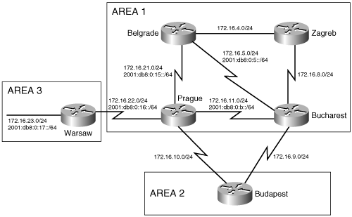
Figure 10-55. A network with multiple L1/L2 routers in area 1 could result in inefficient routing from area 1 to other areas.
Example 10-52. The IS-IS database of an L1 router in area 1 shows two L1/L2 routers with the ATT bit set.
Belgrade#show is database

IS-IS Level-1 Link State Database:
LSPID                 LSP Seq Num  LSP Checksum  LSP Holdtime      ATT/P/OL
Bucharest.00-00       0x00000052   0xE802        1104              1/0/0
Prague.00-00          0x00000052   0xEDC1        1099              1/0/0
Zagreb.00-00          0x0000003B   0x13A5        1076              0/0/0
Belgrade.00-00      * 0x00000050   0x5EC1        485               0/0/0
Belgrade#
Belgrade’s IS-IS database shows all routers in area 1. Prague and Bucharest are both L1/L2 routers and, therefore, have set the ATT bit. Recall that L1 routers use the closest L1/L2 router to forward traffic out of the area. Both L1/L2 routers are equal distance to Belgrade. Belgrade’s IPv4 route table (Example 10-53) and IPv6 route table (Example 10-54) show that the both Bucharest and Prague will be used to forward traffic out of the area.
Example 10-53. The IPv4 route table on the L1 router Belgrade shows two paths out of the area, indicated by two default routes.
Belgrade#show ip route
Codes: C - connected, S - static, R - RIP, M - mobile, B – BGP
       D - EIGRP, EX - EIGRP external, O - OSPF, IA - OSPF inter area
       N1 - OSPF NSSA external type 1, N2 - OSPF NSSA external type 2
       E1 - OSPF external type 1, E2 - OSPF external type 2
       i - IS-IS, su - IS-IS summary, L1 - IS-IS level-1, L2 - IS-IS level-2
       ia - IS-IS inter area, * - candidate default, U - per-user static route
       o - ODR, P - periodic downloaded static route
Gateway of last resort is 172.16.5.1 to network 0.0.0.0
     172.16.0.0/24 is subnetted, 8 subnets
C       172.16.21.0 is directly connected, Serial0/0.1
i L1    172.16.22.0 [115/20] via 172.16.21.2, Serial0/0.1
i L1    172.16.8.0 [115/20] via 172.16.4.2, Serial0/0.2
                   [115/20] via 172.16.5.1, Serial0/0.3
i L1    172.16.9.0 [115/20] via 172.16.5.1, Serial0/0.3
i L1    172.16.10.0 [115/20] via 172.16.21.2, Serial0/0.1
i L1    172.16.11.0 [115/20] via 172.16.21.2, Serial0/0.1
                    [115/20] via 172.16.5.1, Serial0/0.3
C       172.16.4.0 is directly connected, Serial0/0.2
C       172.16.5.0 is directly connected, Serial0/0.3
i*L1 0.0.0.0/0 [115/10] via 172.16.5.1, Serial0/0.3
               [115/10] via 172.16.21.2, Serial0/0.1
Belgrade#
Example 10-54. The IPv6 route table on the L1 router Belgrade shows two paths out of the area, indicated by two default routes.
Belgrade#show ipv6 route
IPv6 Routing Table - 9 entries
Codes: C - Connected, L - Local, S - Static, R - RIP, B – BGP
       U - Per-user Static route
       I1 - ISIS L1, I2 - ISIS L2, IA - ISIS interarea, IS - ISIS summary
       O - OSPF intra, OI - OSPF inter, OE1 - OSPF ext 1, OE2 - OSPF ext 2
       ON1 - OSPF NSSA ext 1, ON2 - OSPF NSSA ext 2
I1  ::/0 [115/10]
     via FE80::204:C1FF:FE50:E700, Serial0/0.1
     via FE80::204:C1FF:FE50:F1C0, Serial0/0.3
C   2001:DB8:0:5::/64 [0/0]
     via ::, Serial0/0.3
L   2001:DB8:0:5::2/128 [0/0]
     via ::, Serial0/0.3
I1  2001:DB8:0:B::/64 [115/20]
     via FE80::204:C1FF:FE50:F1C0, Serial0/0.3
     via FE80::204:C1FF:FE50:E700, Serial0/0.1
C   2001:DB8:0:15::/64 [0/0]
     via ::, Serial0/0.1
L   2001:DB8:0:15::1/128 [0/0]
     via ::, Serial0/0.1
I1  2001:DB8:0:16::/64 [115/20]
     via FE80::204:C1FF:FE50:E700, Serial0/0.1
L   FE80::/10 [0/0]
     via ::, Null0
L   FF00::/8 [0/0]
     via ::, Null0
Belgrade#
As you can see in Example 10-53 and Example 10-54, only L1 routes are in Belgrade’s route table. All addresses outside of the area follow the path indicated by the default route. The default routes (IPv4: 0.0.0.0/0, IPv6: ::/0) show two next-hop addresses, one via Bucharest (S0/0.3) and one via Prague (S0/0.1).
172.16.23.0/24 and 2001:db8:0:17::/64 are addresses connected to the Warsaw router, in area 3. The best path for Belgrade to take to these addresses is via Prague. However, because both Bucharest and Prague are equal distance L1/L2 routers, Belgrade will load share between the L1/L2 routers when sending traffic to 172.16.23.0/24 or 2001:db8:0:17::/64. Half of the traffic will take the optimal path, the other half will take a longer path. Example 10-55 shows Belgrade pinging 172.16.23.1 and recording the route. One route is via Bucharest (172.16.11.2), the other is via Prague (172.16.22.2).
Example 10-55. Ping with the record route option shows the round trip path a packet takes from Belgrade to Warsaw.
Belgrade#ping
Protocol [ip]:
Target IP address: 172.16.23.1
Extended commands [n]: y
Loose, Strict, Record, Timestamp, Verbose[none]: r
Loose, Strict, Record, Timestamp, Verbose[RV]:
Type escape sequence to abort.
Sending 5, 100-byte ICMP Echos to 172.16.23.1, timeout is 2 seconds:
<...>Reply to request 0 (416 ms).  Received packet has options
 Total option bytes= 40, padded length=40
 Record route:
   (172.16.5.2)
   (172.16.11.2)
   (172.16.22.2)
   (172.16.23.1)
   (172.16.22.1)
   (172.16.21.2)
   (172.16.5.2) <*>
   (0.0.0.0)
   (0.0.0.0)
 End of list
Reply to request 1 (216 ms).  Received packet has options
 Total option bytes= 40, padded length=40
 Record route:
   (172.16.21.1)
   (172.16.22.2)
   (172.16.23.1)
   (172.16.22.1)
   (172.16.21.2)
   (172.16.21.1) <*>
   (0.0.0.0)
   (0.0.0.0)
   (0.0.0.0)
End of list
The path that the traffic takes from Belgrade to 172.16.23.0 can be controlled by advertising the address to the L1 routers in area 1. This advertising of L2 routes to L1 router is called route leaking. The downside of route leaking is that the L1 router needs to keep track of additional addresses and paths to those addresses.
Route leaking is configured by creating a list containing the addresses to be advertised into the area, and then configuring the distribution of this list to the L1 routers. Prague’s configuration is displayed in Example 10-56.
Example 10-56. Prague is configured to leak routes L2 routes into the L1 area.
access-list 100 permit ip 172.16.23.0 0.0.0.255 any
ipv6 prefix-list warsaw seq 5 permit 2001:DB8:0:17::/64
router isis
 redistribute isis ip level-2 into level-1 distribute-list 100
 address-family ipv6
  redistribute isis level-2 into level-1 distribute-list warsaw
 exit-address-family
The access list number 100 defines the IPv4 addresses to be advertised and the prefix-list named warsaw defines the IPv6 addresses to be advertised. The redistribute isis ip command looks for L2 IPv4 addresses that match the list 100 and advertises them to L1 routers within the area. The redistribute isis command listed under the address-family ipv6 command looks for L2 IPv6 addresses that match those defined in the prefix-list named warsaw, and advertises them to the L1 area. Access-lists are discussed in Appendix B, and route redistribution is discussed in more detail in Chapter 11.
Leaked routes are advertised the same way as other addresses: in type 128, 130, or 135 IPv4 Reachability TLVs, and type 236 and 237 IPv6 Reachability TLVs. TLV 128 and 130 are used with narrow-type metrics, and 135 is used with wide metrics. To distinguish leaked routes from other connected IP routes or external IP routes an Up/Down bit is defined, as discussed previously in the section “Domain-Wide Prefix Distribution.” If the Up/Down bit is set to 0, the route originated in this L1 area. If the Up/Down bit is set to 1, the route was leaked from L2. Setting this bit helps keeps route loops from occurring. A L1/L2 router will not advertise an L1 address that has the Up/Down bit set to another L2 router.
A route that was leaked into L1 is identifiable in the route table and in the IS-IS database. Example 10-57 and Example 10-58 display Belgrade’s IPv4 and IPv6 route tables, respectively, and Example 10-59 displays Belgrade’s IS-IS database.
Example 10-57. The leaked address in the route table is identified as an “ia” route, or inter-area route.
Belgrade#show ip route
Codes: C - connected, S - static, R - RIP, M - mobile, B – BGP
       D - EIGRP, EX - EIGRP external, O - OSPF, IA - OSPF inter area
       N1 - OSPF NSSA external type 1, N2 - OSPF NSSA external type 2
       E1 - OSPF external type 1, E2 - OSPF external type 2
       i - IS-IS, su - IS-IS summary, L1 - IS-IS level-1, L2 - IS-IS level-2
       ia - IS-IS inter area, * - candidate default, U - per-user static route
       o - ODR, P - periodic downloaded static route
Gateway of last resort is 172.16.5.1 to network 0.0.0.0
     172.16.0.0/24 is subnetted, 9 subnets
C       172.16.21.0 is directly connected, Serial0/0.1
i L1    172.16.22.0 [115/20] via 172.16.21.2, Serial0/0.1
i ia    172.16.23.0 [115/30] via 172.16.21.2, Serial0/0.1
i L1    172.16.8.0 [115/20] via 172.16.4.2, Serial0/0.2
                   [115/20] via 172.16.5.1, Serial0/0.3
i L1    172.16.9.0 [115/20] via 172.16.5.1, Serial0/0.3
i L1    172.16.10.0 [115/20] via 172.16.21.2, Serial0/0.1
i L1    172.16.11.0 [115/20] via 172.16.21.2, Serial0/0.1
                    [115/20] via 172.16.5.1, Serial0/0.3
C       172.16.4.0 is directly connected, Serial0/0.2
C       172.16.5.0 is directly connected, Serial0/0.3
i*L1 0.0.0.0/0 [115/10] via 172.16.5.1, Serial0/0.3
               [115/10] via 172.16.21.2, Serial0/0.1
Belgrade#
Example 10-58. The leaked IPv6 address in the route table is identified as “IA,” inter-area.
Belgrade#show ipv6 route
IPv6 Routing Table - 10 entries
Codes: C - Connected, L - Local, S - Static, R - RIP, B – BGP
       U - Per-user Static route
       I1 - ISIS L1, I2 - ISIS L2, IA - ISIS interarea, IS - ISIS summary
       O - OSPF intra, OI - OSPF inter, OE1 - OSPF ext 1, OE2 - OSPF ext 2
       ON1 - OSPF NSSA ext 1, ON2 - OSPF NSSA ext 2
I1  ::/0 [115/10]
     via FE80::204:C1FF:FE50:E700, Serial0/0.1
     via FE80::204:C1FF:FE50:F1C0, Serial0/0.3
C   2001:DB8:0:5::/64 [0/0]
     via ::, Serial0/0.3
L   2001:DB8:0:5::2/128 [0/0]
     via ::, Serial0/0.3
I1  2001:DB8:0:B::/64 [115/20]
     via FE80::204:C1FF:FE50:F1C0, Serial0/0.3
     via FE80::204:C1FF:FE50:E700, Serial0/0.1
C   2001:DB8:0:15::/64 [0/0]
     via ::, Serial0/0.1
L   2001:DB8:0:15::1/128 [0/0]
     via ::, Serial0/0.1
I1  2001:DB8:0:16::/64 [115/20]
     via FE80::204:C1FF:FE50:E700, Serial0/0.1
IA  2001:DB8:0:17::/64 [115/30]
     via FE80::204:C1FF:FE50:E700, Serial0/0.1
L   FE80::/10 [0/0]
     via ::, Null0
L   FF00::/8 [0/0]
     via ::, Null0
Belgrade#
Example 10-59. The leaked address in the IS-IS database is identified as an IP-inter-area address.
Belgrade#show is database Prague.00-00 detail l1
IS-IS Level-1 LSP Prague.00-00
LSPID                 LSP Seq Num  LSP Checksum  LSP Holdtime      ATT/P/OL
Prague.00-00          0x0000006D   0x7A37        655               1/0/0
  Area Address: 01
  Topology:     IPv4 (0x0) IPv6 (0x4002 ATT)
  NLPID:        0xCC 0x8E
  Hostname: Prague
  IP Address:   172.16.11.1
  Metric: 10         IP 172.16.22.0/24
  Metric: 10         IP 172.16.21.0/24
  Metric: 10         IP 172.16.10.0/24
  Metric: 10         IP 172.16.11.0/24
  IPv6 Address: 2001:DB8:0:15::2
  Metric: 10         IPv6 (MT-IPv6) 2001:DB8:0:16::/64
  Metric: 10         IPv6 (MT-IPv6) 2001:DB8:0:15::/64
  Metric: 10         IPv6 (MT-IPv6) 2001:DB8:0:B::/64
  Metric: 10         IS-Extended Belgrade.00
  Metric: 10         IS-Extended Bucharest.00
  Metric: 10         IS (MT-IPv6) Belgrade.00
  Metric: 10         IS (MT-IPv6) Bucharest.00
  Metric: 20         IP-Interarea 172.16.23.0/24
  Metric: 20         IPv6-Interarea (MT-IPv6) 2001:DB8:0:17::/64
Belgrade#
The route tables display the IPv4 and IPv6 routes as IS-IS inter-area routes, designated by the type “ia” for IPv4 and “IA” for IPv6. The database entry for the router that originated the leak shows the addresses as IP-Interarea and IPv6-Interarea.
IOS supports the ability to have multiple, active, L1 areas on a single router: Up to 29 L1 areas can be configured, but only one L2 area. By default, the first configured IS-IS routing process defines the L2 area. It can also define a single L1 area. To enable additional L1 areas on the router, additional IS-IS routing processes are defined. Routers within each of the configured L1 areas can communicate together via this L1/L2 router. Because each area does not have to have a unique L1/L2 router to reach the rest of the network, the number of L1/L2 routers is minimized.
In the network of Figure 10-55, Warsaw is in area 3. The Warsaw router is an L1/L2 router for the area. The only connection from Warsaw to the rest of the network is via Prague. Prague’s configuration is modified so that Prague becomes the L2 router for both areas 1 and 3. Prague’s new configuration is displayed in Example 10-60.
Example 10-60. Prague is configured with multiple L1 areas.
router isis
 net 01.0004.c150.e700.00
 metric-style wide
 address-family ipv6
  multi-topology

router isis three
 net 03.0004.c150.e700.00
 metric-style wide
 address-family ipv6
  multi-topology

interface Serial0/0.1 point-to-point
 description Warsaw
 ip address 172.16.22.2 255.255.255.0
 ipv6 address 2001:db8:0:16::2/64
 ip router isis three
 ipv6 router isis three
The second IS-IS routing process is called “three.” IS-IS three is assigned to the interface connecting Prague to Warsaw, interface Serial 0/0.1. IS-IS “three” is automatically configured as a L1 area, as seen by the show clns neighbor command on Prague (Example 10-61).
Example 10-61. Multiple L1 areas are configured on Prague.
Prague#show clns neighbor
Area null:
System Id      Interface   SNPA                 State  Holdtime  Type Protocol
Budapest       Se0/0.3     DLCI 115             Up     24        L2   IS-IS
Belgrade       Se0/0.2     DLCI 116             Up     26        L1   M-ISIS
Bucharest      Se0/0.4     DLCI 113             Up     22        L1L2 M-ISIS
Area three:
System Id      Interface   SNPA                 State  Holdtime  Type Protocol
Warsaw         Se0/0.1     DLCI 117             Up     28        L1   M-ISIS
Prague#
Warsaw can now be configured as a L1 router, because all its neighbors exist in area 3 (see Example 10-62). In this simple network, this step is not needed because Warsaw’s only connection outside area 3 is to Prague, which only uses L1 communication with Warsaw. This step might be desired in larger networks, to ensure that Warsaw does not attempt L2 connections to other routers.
Example 10-63 shows Warsaw’s IS-IS database and the route table as a L1/L2 router. Example 10-64 shows the same tables with Warsaw as a L1 router.
Example 10-63. Warsaw’s database includes entries for area 3 routers and all L2 routers.
Warsaw#show is database
IS-IS Level-1 Link State Database:
LSPID                 LSP Seq Num  LSP Checksum  LSP Holdtime      ATT/P/OL
Prague.00-00          0x0000000A   0x08B1        1048              1/0/0
Warsaw.00-00        * 0x00000075   0x3D13        1085              1/0/0
IS-IS Level-2 Link State Database:
LSPID                 LSP Seq Num  LSP Checksum  LSP Holdtime      ATT/P/OL
Bucharest.00-00       0x0000007A   0x59D0        1060              0/0/0
Prague.00-00          0x00000090   0x433A        1078              0/0/0
Warsaw.00-00        * 0x00000001   0xA828        1080              0/0/0
Budapest.00-00        0x00000073   0xFE95        344               0/0/0
Budapest.01-00        0x00000066   0xFF8B        444               0/0/0
Warsaw#show ip route
Codes: C - connected, S - static, R - RIP, M - mobile, B – BGP
       D - EIGRP, EX - EIGRP external, O - OSPF, IA - OSPF inter area
       N1 - OSPF NSSA external type 1, N2 - OSPF NSSA external type 2
       E1 - OSPF external type 1, E2 - OSPF external type 2
       i - IS-IS, su - IS-IS summary, L1 - IS-IS level-1, L2 - IS-IS level-2
       ia - IS-IS inter area, * - candidate default, U - per-user static route
       o - ODR, P - periodic downloaded static route
Gateway of last resort is not set
     172.16.0.0/24 is subnetted, 10 subnets
i L2    172.16.21.0 [115/20] via 172.16.22.2, Serial0/0.1
C       172.16.22.0 is directly connected, Serial0/0.1
C       172.16.23.0 is directly connected, FastEthernet0/0
i L2    172.16.12.0 [115/30] via 172.16.22.2, Serial0/0.1
i L2    172.16.8.0 [115/30] via 172.16.22.2, Serial0/0.1
i L2    172.16.9.0 [115/30] via 172.16.22.2, Serial0/0.1
i L2    172.16.10.0 [115/20] via 172.16.22.2, Serial0/0.1
i L2    172.16.11.0 [115/20] via 172.16.22.2, Serial0/0.1
i L2    172.16.4.0 [115/30] via 172.16.22.2, Serial0/0.1
i L2    172.16.5.0 [115/30] via 172.16.22.2, Serial0/0.1
Warsaw#
Example 10-64. Warsaw’s database includes only area 3 routers and links, and its route tables contain only a default route for addresses not in area 3.
Warsaw#show is database

IS-IS Level-1 Link State Database:
LSPID                 LSP Seq Num  LSP Checksum  LSP Holdtime      ATT/P/OL
Prague.00-00          0x00000009   0x2BDF        923               1/0/0
Warsaw.00-00        * 0x00000073   0x6CF3        924               0/0/0
Warsaw#show ip route
Codes: C - connected, S - static, R - RIP, M - mobile, B – BGP
       D - EIGRP, EX - EIGRP external, O - OSPF, IA - OSPF inter area
       N1 - OSPF NSSA external type 1, N2 - OSPF NSSA external type 2
       E1 - OSPF external type 1, E2 - OSPF external type 2
       i - IS-IS, su - IS-IS summary, L1 - IS-IS level-1, L2 - IS-IS level-2
       ia - IS-IS inter area, * - candidate default, U - per-user static route
       o - ODR, P - periodic downloaded static route
Gateway of last resort is 172.16.22.2 to network 0.0.0.0
     172.16.0.0/24 is subnetted, 2 subnets
C       172.16.22.0 is directly connected, Serial0/0.1
C       172.16.23.0 is directly connected, FastEthernet0/0
i*L1 0.0.0.0/0 [115/10] via 172.16.22.2, Serial0/0.1
Warsaw#
When Warsaw was the L1/L2 router for area 3, the IS database contained entries for each router in area 3 and entries for each L2 router and all the addresses those L2 routers could reach. The route table contained entries for every reachable address in the network. As an L1 router, Warsaw has reduced the size of its IS-IS database and its route table significantly.
The basic methods for troubleshooting IS-IS are very similar to the methods for troubleshooting OSPF, as discussed in Chapter 8. A major aspect of troubleshooting Integrated IS-IS that is different from the other IP routing protocols is that IS-IS uses CLNS PDUs rather than IP packets. If you are troubleshooting the protocol itself, remember that you are troubleshooting CLNS, not IP.
As with all routing protocols, the first troubleshooting step is to check the route table for accurate information. If an expected route entry is missing or incorrect, the remainder of the troubleshooting task is to determine the source of the problem.
After the route table, the link-state database is the most important source of troubleshooting information. As recommended in Chapter 8, it is good practice to keep a copy of the L1 link-state database for every area, and a copy of the L2 link-state database. These stored copies of the databases should be updated regularly, as part of your routine baselining procedures. When things go wrong, these stored databases provide a steady-state reference.
When examining an individual router’s configuration, consider the following:
Does the net statement under the IS-IS configuration specify the correct NET? Are the Area ID and System ID correct for this router? Does the NET comply with whatever CLNS addressing convention is being used in this network?
Is IS-IS enabled on the correct interfaces with the ip router isis or ipv6 router isis command?
Are the IP addresses and subnet masks or prefixes correct? It is doubly important to check these in an Integrated IS-IS environment because a misconfigured IP address will not prevent an IS-IS adjacency from being partially established.
The command show clns is-neighbors displays the IS-IS neighbor table. The entire table is displayed by default, or you can specify a particular interface. From this table, you can observe whether all expected neighbors are present and whether they are the correct type. For more information, such as the area addresses and IP addresses associated with each neighbor and the uptime of each neighbor, use the show clns is-neighbors detail command.
When examining adjacencies, consider the following:
Are the router levels configured correctly? L1 routers can establish adjacencies only with L1 and L1/L2 routers, and L2 routers can establish adjacencies only with L2 and L1/L2 routers.
Are Hellos being sent from both neighbors? Are the Hellos the correct level, and do they contain the correct parameters? The command debug isis adj-packets is useful for observing Hellos.
If authentication is being used, are the passwords and authentication mode the same between neighbors? Remember that area (level 1) and domain (level 2) authentication do not regulate adjacencies, only the exchange of LSPs.
Are any access lists blocking IS-IS or CLNS?
A change has been made on the router Bonn in Figure 10-54. Bonn and Frankfurt are no longer accessible via IPv4 from other locations. A look at Bonn’s IPv4 route table (Example 10-65) shows that there are no IP routes learned via Madrid (interface Serial0/0.1).
Example 10-65. Bonn’s IPv4 route table shows IS-IS learned routes from Frankfurt on FA0/0, but nothing from Madrid on Serial0/0.1.
Bonn#show ip route
Codes: C - connected, S - static, R - RIP, M - mobile, B – BGP
       D - EIGRP, EX - EIGRP external, O - OSPF, IA - OSPF inter area
       N1 - OSPF NSSA external type 1, N2 - OSPF NSSA external type 2
       E1 - OSPF external type 1, E2 - OSPF external type 2
       i - IS-IS, su - IS-IS summary, L1 - IS-IS level-1, L2 - IS-IS level-2
       ia - IS-IS inter area, * - candidate default, U - per-user static route
       o - ODR, P - periodic downloaded static route
Gateway of last resort is not set
     172.16.0.0/16 is variably subnetted, 8 subnets, 2 masks
C       172.16.24.0/24 is directly connected, Loopback1
C       172.16.25.0/24 is directly connected, Loopback2
i L1    172.16.16.0/24 [115/20] via 172.16.19.2, FastEthernet0/0
i su    172.16.16.0/21 [115/10] via 0.0.0.0, Null0
i L1    172.16.17.0/24 [115/20] via 172.16.19.2, FastEthernet0/0
i L1    172.16.18.0/24 [115/20] via 172.16.19.2, FastEthernet0/0
C       172.16.19.0/24 is directly connected, FastEthernet0/0
C       172.16.9.0/24 is directly connected, Serial0/0.1
Bonn#
The command show clns is-neighbors shows an adjacency exists from Bonn to Madrid (Example 10-66). However, notice Madrid’s type is IS rather than L1 or L2. This indicates a problem with the adjacency. debug isis adj-packets gives a hint as to where the problem exists (Example 10-67).
Example 10-66. Bonn’s CLNS IS-IS neighbor table shows an adjacency exists to Madrid and to Frankfurt, but there is something wrong with the Madrid adjacency.
Bonn#show clns is-neighbors
System Id      Interface   State  Type Priority  Circuit Id          Format
Madrid         Se0/0.1     Up     IS   0         00                  Phase V
Frankfurt      Fa0/0       Up     L1   64        Bonn.03             Phase V
Bonn#
Example 10-67. The details of IS-IS Hellos (IIHs) can be observed with the debug isis adj-packets command. This display is from router Bonn in Figure 10-54 and shows that there is a problem with the IP address on Serial0/0.1.
Bonn#debug isis adj-packets
IS-IS Adjacency related packets debugging is on
Bonn#
ISIS-Adj: Sending serial IIH on Serial0/0.1, length 1499
ISIS-Adj: Rec serial IIH from DLCI 171 (Serial0/0.1), cir type L2, cir id 01, length 1499
ISIS-Adj: No usable IP interface addresses in serial IIH from Serial0/0.1
ISIS-Adj: Sending L1 LAN IIH on FastEthernet0/0, length 1497
ISIS-Adj: Sending L2 LAN IIH on FastEthernet0/0, length 1497
ISIS-Adj: Sending L1 LAN IIH on FastEthernet0/0, length 1497
ISIS-Adj: Rec L1 IIH from 0000.0c8d.34f1 (FastEthernet0/0), cir type L1, cir id
0000.0C0A.2AA9.03, length 1497
Reviewing the IPv4 addresses on Bonn shows that the IP address on Serial0/0.1 have been inadvertently changed. IOS checks the addresses in the TLVs before establishing adjacencies. If the IPv4 address in the Interface Address TLV, 132, does not belong to the same subnet as the receiving interface, an adjacency is formed, but the type of the adjacency will be IS rather then L1 or L2, indicating that there is a problem with the configuration affecting the adjacency. After correcting the problem, Bonn’s CLNS IS neighbor table (Example 10-68) and IPv4 route table look good.
Example 10-68. A problem free CLNS neighbor table shows the adjacency type is L1, L2, or L1/L2. Bonn’s route table shows IP routes from both adjacent neighbors.
Bonn#show clns is-neighbors
System Id      Interface   State  Type Priority  Circuit Id         Format
Madrid         Se0/0.1     Up     L2   0         00                 Phase V
Madrid         Fa0/0       Up     L1   64        Bonn.03            Phase V
Bonn#show ip route
Codes: C - connected, S - static, R - RIP, M - mobile, B – BGP
       D - EIGRP, EX - EIGRP external, O - OSPF, IA - OSPF inter area
       N1 - OSPF NSSA external type 1, N2 - OSPF NSSA external type 2
       E1 - OSPF external type 1, E2 - OSPF external type 2
       i - IS-IS, su - IS-IS summary, L1 - IS-IS level-1, L2 - IS-IS level-2
       ia - IS-IS inter area, * - candidate default, U - per-user static route
       o - ODR, P - periodic downloaded static route
Gateway of last resort is not set
     172.16.0.0/16 is variably subnetted, 11 subnets, 2 masks
C       172.16.24.0/24 is directly connected, Loopback1
C       172.16.25.0/24 is directly connected, Loopback2
i L2    172.16.21.0/24 [115/20] via 172.16.9.1, Serial0/0.1
i L1    172.16.16.0/24 [115/20] via 172.16.19.2, FastEthernet0/0
i su    172.16.16.0/21 [115/10] via 0.0.0.0, Null0
i L1    172.16.17.0/24 [115/20] via 172.16.19.2, FastEthernet0/0
i L1    172.16.18.0/24 [115/20] via 172.16.19.2, FastEthernet0/0
C       172.16.19.0/24 is directly connected, FastEthernet0/0
i L2    172.16.8.0/24 [115/20] via 172.16.9.1, Serial0/0.1
C       172.16.9.0/24 is directly connected, Serial0/0.1
i L2    172.16.0.0/21 [115/30] via 172.16.9.1, Serial0/0.1
Bonn#
The output from the command debug isis adj-packets performed on a problem free Bonn is shown in Example 10-69. Information is being received over Serial0/0.1.
Example 10-69. The details of IS-IS Hellos (IIHs) are observed on a correctly configured router, Bonn.
Bonn#debug isis adj-packets
IS-IS Adjacency related packets debugging is on
Bonn#
ISIS-Adj: Sending L1 LAN IIH on FastEthernet0/0, length 1497
ISIS-Adj: Sending L2 LAN IIH on FastEthernet0/0, length 1497
ISIS-Adj: Rec L1 IIH from 0000.0c8d.34f1 (FastEthernet0/0), cir type L1, cir id
0000.0C0A.2AA9.03, length 1497
ISIS-Adj: Rec serial IIH from DLCI 171 (Serial0/0.1), cir type L2, cir id 01, length 1499
ISIS-Adj: Local mode (IP, IPv6), remote mode (IP, IPv6)
ISIS-Adj: rcvd state UP, old state UP, new state UP
ISIS-Adj: Action = ACCEPT
ISIS-Adj: Sending L1 LAN IIH on FastEthernet0/0, length 1497l
ISIS-Adj: Sending serial IIH on Serial0/0.1, length 1499
Bonn#
A similar adjacency problem exists with IPv6 in single topology mode, if IPv6 is not configured on every link that is configured with IPv4. When the network in Figure 10-54 was configured with IPv6 in single topology mode, a problem arose between Bonn and Frankfurt. Frankfurt does not support IPv6. Example 10-48 shows the output from the debug is adj-packets on Bonn. The debug’s output shows that there is a problem with the link-local address: “No usable IPv6 linklocal addresses in LAN IIH from FastEthernet0/0.” IOS on Bonn checks for valid addresses and address families before establishing adjacencies. In single topology mode, if both IPv4 and IPv6 are configured on the router, every link that has an IPv4 address must also have an IPv6 address, every link that has an IPv6 address must also have an IPv4 address, and neighbor routers must also have valid IPv4 and IPv6 addresses. TLV 232 contains the IPv6 Link Local address in Hello packets. If in single topology mode, a neighbor router does not include a valid IPv6 link-local address in its hello packets, the adjacency will be formed as a type IS (again, indicating a problem with the configuration).
There is an IS-IS process configuration command, log-adjacency-changes. This command will log all adjacency changes to the log, whether buffered or sent to a log server. Perusing the log is very useful for troubleshooting adjacency problems that occurred at some time in the past.
The IS-IS link-state database is examined with the command show isis database. If the router is an L1/L2, both of the databases are displayed by default. To observe only one of the databases, use the level-1 or level-2 keywords. To examine the LSPs in more detail, use the detail keyword. A single LSP can be observed by specifying its LSPID, as in Example 10-70.
Example 10-70. This LSP is from the L2 database of router Zurich in Figure 10-54.
Zurich#show isis database detail Madrid.00-00
IS-IS Level-2 LSP Madrid.00-00
LSPID                 LSP Seq Num  LSP Checksum  LSP Holdtime      ATT/P/OL
Madrid.00-00          0x0000007C   0x5874        1023              0/0/0
  Auth:         Length: 17
  Area Address: 03
  Topology:     IPv4 (0x0) IPv6 (0x2)
  NLPID:        0xCC 0x8E
  Hostname: Madrid
  IP Address: 172.16.21.2
  IPv6 Address: 2001:DB8:0:15::2
  Metric: 10         IS-Extended Zurich.00
  Metric: 10         IS-Extended Bonn.00
  Metric: 10         IS-Extended Geneva.00
  Metric: 10         IS (MT-IPv6) Zurich.00
  Metric: 10         IS (MT-IPv6) Bonn.00
  Metric: 10         IS (MT-IPv6) Geneva.00
  Metric: 10         IP 172.16.21.0/24
  Metric: 10         IP 172.16.8.0/24
  Metric: 10         IP 172.16.9.0/24
  Metric: 10         IPv6 (MT-IPv6) 2001:DB8:0:8::/64
  Metric: 10         IPv6 (MT-IPv6) 2001:DB8:0:9::/64
  Metric: 10         IPv6 (MT-IPv6) 2001:DB8:0:15::/64
Zurich#
A sequence number that is noticeably higher than the sequence numbers of other LSPs might indicate instability either within the area or on the level 2 backbone. Another hint of instability is an LSP Holdtime that never gets very small. If instability is suspected, use the command show isis spf-log to list all SPF calculations recently performed by the router.
In Example 10-71, the SPF log for router Geneva in Figure 10-54 is shown. Nothing but the periodic SPF calculations triggered by the 15-minute database refreshes are shown until approximately three minutes before the log was displayed. At that time, frequent SPF calculations began occurring, indicating frequent changes of some sort in the network.[27]
Example 10-71. This SPF log reveals instability in area 1 of Figure 10-54.
Geneva#sh isis spf-log
     Level 1 SPF log
   When      Duration   Nodes   Count    Last trigger LSP     Triggers
02:43:09          12       3       1                         PERIODIC
02:28:08          12       3       1                         PERIODIC
02:13:06          12       3       1                         PERIODIC
01:58:05          12       3       1                         PERIODIC
01:43:03          12       3       1                         PERIODIC
01:28:02          12       3       1                         PERIODIC
01:13:00          12       3       1                         PERIODIC
00:57:59          12       3       1                         PERIODIC
00:42:58          12       3       1                         PERIODIC
00:27:56          12       3       1                         PERIODIC
00:12:55          12       3       1                         PERIODIC
00:03:08          8        3       1   0000.0C76.5B7C.00-00  LSPHEADER
00:02:35          8        3       1   0000.0C76.5B7C.00-00  LSPHEADER
00:02:23          8        3       1   0000.0C76.5B7C.00-00  LSPHEADER
00:01:50          8        3       1   0000.0C76.5B7C.00-00  LSPHEADER
00:01:14          4        1       1   0000.0C0A.2C51.00-00  TLVCONTENT
00:00:46          4        2       2   0000.0C0A.2C51.04-00  NEWLSP TLVCONTENT
00:00:20          4        1       3   0000.0C0A.2C51.00-00  NEWADJ TLVCONTENT
00:00:08          8        3       1   0000.0C76.5B7C.02-00  TLVCONTENT
Geneva#
To further investigate instabilities revealed by the SPF log, three useful debug commands are available. Example 10-72, Example 10-73, and Example 10-74 show output from these three debug functions. In each case, the debug messages show the results of disconnecting and reconnecting the serial interface of Bonn in Figure 10-54 from the perspective of Frankfurt. The first, debug isis spf-triggers (Example 10-72), displays messages pertaining to events that trigger an SPF calculation. The second command is debug isis spf-events (Example 10-73). This command displays a detailed account of the SPF calculations caused by a triggering event. The third command, debug isis spf-statistics (Example 10-74), displays information about the SPF calculation itself. Of particular interest is the time taken to complete the calculation, which can reveal performance problems on the router.
Example 10-72. debug isis spf-triggers displays messages about events that trigger an SPF calculation.
Frankfurt#debug isis spf-triggers
IS-IS SPF triggering events debugging is on
Frankfurt#
ISIS-Spf: L1, LSP fields changed 0000.0C0A.2AA9.00-00
ISIS-Spf: L1, LSP fields changed 0000.0C0A.2AA9.00-00
Frankfurt#
Example 10-73. debug isis spf-events displays the details of an SPF calculation.
Frankfurt#debug isis spf-events
IS-IS SPF events debugging is on
Frankfurt#
ISIS-Spf: L1 LSP 4 (0000.0C0A.2AA9.00-00) flagged for recalculation from 37D73FA
ISIS-Spf: Calculating routes for L1 LSP 4 (0000.0C0A.2AA9.00-00)
ISIS-Spf: Add 172.16.19.0/255.255.255.0 to IP RIB, metric 20
ISIS-Spf: Next hop 0000.0C0A.2AA9/172.16.19.1 (Ethernet0) (rejected)
ISIS-Spf: Redundant IP route 172.16.24.0/255.255.255.0, metric 20, not added
ISIS-Spf: Redundant IP route 172.16.25.0/255.255.255.0, metric 20, not added
ISIS-Spf: Aging L1 LSP 4 (0000.0C0A.2AA9.00-00), version 105
ISIS-Spf: Aging IP 172.16.9.0/255.255.255.0, next hop 172.16.19.1
ISIS-Spf: Deleted NDB
ISIS-Spf:  Compute L1 SPT
ISIS-Spf: 3 nodes for level-1
ISIS-Spf: Move 0000.0C8D.34F1.00-00 to PATHS, metric 0
ISIS-Spf: Add 0000.0C0A.2AA9.03-00 to TENT, metric 10
ISIS-Spf: Move 0000.0C0A.2AA9.03-00 to PATHS, metric 10
ISIS-Spf: thru 0/2147483647/0, delay 0/0/0, mtu 0/2147483647/0, hops 0/0/0, ticks
0/0/0
ISIS-Spf: considering adj to 0000.0C0A.2AA9 (Ethernet0) metric 10, level 1, circuit
3, adj 1
ISIS-Spf:   (accepted)
ISIS-Spf: Add 0000.0C0A.2AA9.00-00 to TENT, metric 10
ISIS-Spf:   Next hop 0000.0C0A.2AA9 (Ethernet0)
ISIS-Spf: Move 0000.0C0A.2AA9.00-00 to PATHS, metric 10
ISIS-Spf: Add 172.16.19.0/255.255.255.0 to IP RIB, metric 20
ISIS-Spf: Next hop 0000.0C0A.2AA9/172.16.19.1 (Ethernet0) (rejected)
ISIS-Spf: Redundant IP route 172.16.24.0/255.255.255.0, metric 20, not added
ISIS-Spf: Redundant IP route 172.16.25.0/255.255.255.0, metric 20, not added
ISIS-Spf: Aging L1 LSP 2 (0000.0C8D.34F1.00-00), version 101
ISIS-Spf: Aging L1 LSP 3 (0000.0C0A.2AA9.03-00), version 99
ISIS-Spf: Aging L1 LSP 4 (0000.0C0A.2AA9.00-00), version 106
ISIS-Spf: Remove stale 0/0 from IP RIB
ISIS-Spf: L1 LSP 4 (0000.0C0A.2AA9.00-00) flagged for recalculation from 37D73FA
ISIS-Spf: Calculating routes for L1 LSP 4 (0000.0C0A.2AA9.00-00)
ISIS-Spf: Add 172.16.19.0/255.255.255.0 to IP RIB, metric 20
ISIS-Spf: Next hop 0000.0C0A.2AA9/172.16.19.1 (Ethernet0) (rejected)
ISIS-Spf: Add 172.16.9.0/255.255.255.0 to IP RIB, metric 20
ISIS-Spf: Next hop 0000.0C0A.2AA9/172.16.19.1 (Ethernet0) (accepted)
ISIS-Spf: Redundant IP route 172.16.24.0/255.255.255.0, metric 20, not added
ISIS-Spf: Redundant IP route 172.16.25.0/255.255.255.0, metric 20, not added
ISIS-Spf: Aging L1 LSP 4 (0000.0C0A.2AA9.00-00), version 107
Example 10-74. debug isis spf-statistics displays statistical information about the SPF calculation.
Frankfurt#debug isis spf-statistics
IS-IS SPF Timing and Statistics Data debugging is on
Frankfurt#
ISIS-Spf:  Compute L1 SPT
ISIS-Spf: Complete L1 SPT,
ISIS-Spf:  Compute time 0.032/0.032, 2/1 nodes, 0/2 links, 0 suspends
ISIS-Spf:  Compute L1 SPT
ISIS-Spf: Complete L1 SPT,
ISIS-Spf:  Compute time 0.036/0.036, 2/1 nodes, 0/2 links, 0 suspends
Within each area, every router must have an identical link-state database. Additionally, every L1/L2 and L2 router in the IS-IS domain must have an identical L2 database. If you suspect that a router’s link-state database is not correctly synchronized, examine the LSP IDs and the checksums. The same LSP IDs should exist in every database, and the checksum of each LSP should be identical in every database.
Two debug commands can help you observe the synchronization process. The first is debug isis update-packets (Example 10-75), which displays information about SNPs and LSPs the router sends and receives. The second command, debug isis snp-packets (Example 10-76), displays information specific to the CSNPs and PSNPs the router sends and receives.
Example 10-75. debug isis update-packets displays information about SNPs and LSPs.
Frankfurt#debug isis update-packets
IS-IS Update related packet debugging is on
Frankfurt#
ISIS-Upd: Rec L1 LSP 0000.0C0A.2AA9.00-00, seq 10, ht 1199,
ISIS-Upd: from SNPA 0005.5e6b.50a0 (Ethernet0)
ISIS-Upd: LSP newer than database copy
ISIS-Upd: Leaf routes changed
ISIS-Upd: Rec L1 LSP 0000.0C0A.2AA9.00-00, seq 11, ht 1199,
ISIS-Upd: from SNPA 0005.5e6b.50a0 (Ethernet0)
ISIS-Upd: LSP newer than database copy
ISIS-Upd: Important fields changed
ISIS-Upd: Full SPF required
ISIS-Upd: Rec L1 LSP 0000.0C0A.2AA9.00-00, seq 12, ht 1199,
ISIS-Upd: from SNPA 0005.5e6b.50a0 (Ethernet0)
Frankfurt#
Example 10-76. debug isis snp-packets displays detailed information about CSNPs and PSNPs.
Frankfurt#debug isis snp-packets
IS-IS CSNP/PSNP packets debugging is on
Frankfurt#
ISIS-Snp: Rec L1 CSNP from 0000.0C0A.2AA9 (Ethernet0)
ISIS-Snp: CSNP range 0000.0000.0000.00-00 to FFFF.FFFF.FFFF.FF-FF
ISIS-Snp: Same entry 0000.0C04.DCC0.00-00, seq 9
ISIS-Snp: Same entry 0000.0C0A.2AA9.00-00, seq 1A
ISIS-Snp: Same entry 0000.0C0A.2AA9.01-00, seq 6
ISIS-Snp: Rec L1 CSNP from 0000.0C0A.2AA9 (Ethernet0)
ISIS-Snp: CSNP range 0000.0000.0000.00-00 to FFFF.FFFF.FFFF.FF-FF
ISIS-Snp: Same entry 0000.0C04.DCC0.00-00, seq 9
ISIS-Snp: Entry 0000.0C0A.2AA9.00-00, seq 1B is newer than ours (seq 1A), sending PSNP
ISIS-Snp: Same entry 0000.0C0A.2AA9.01-00, seq 6
ISIS-Snp: Build L1 PSNP entry for 0000.0C0A.2AA9.00-00, seq 1A
ISIS-Snp: Sending L1 PSNP on Ethernet0
ISIS-Snp: Rec L1 CSNP from 0000.0C0A.2AA9 (Ethernet0)
ISIS-Snp: CSNP range 0000.0000.0000.00-00 to FFFF.FFFF.FFFF.FF-FF
ISIS-Snp: Same entry 0000.0C04.DCC0.00-00, seq 9
ISIS-Snp: Same entry 0000.0C0A.2AA9.00-00, seq 1B
ISIS-Snp: Same entry 0000.0C0A.2AA9.01-00, seq 6
ISIS-Snp: Rec L1 CSNP from 0000.0C0A.2AA9 (Ethernet0)
ISIS-Snp: CSNP range 0000.0000.0000.00-00 to FFFF.FFFF. FFFF.FF-FF
ISIS-Snp: Same entry 0000.0C04.DCC0.00-00, seq 9
ISIS-Snp: Same entry 0000.0C0A.2AA9.00-00, seq 1B
ISIS-Snp: Same entry 0000.0C0A.2AA9.01-00, seq 6
Frankfurt#Figure 10-56 shows four routers running IS-IS connected by a partially meshed Frame Relay network. The IP addresses, DLCIs, and NETs are shown. The IS-IS configurations of all routers have been verified as correct, and no authentication is configured.

The problem with this network is that no routes are being discovered (Example 10-77). The IP addresses of neighbors’ Frame Relay interfaces can be pinged, but the addresses of the routers’ other interfaces cannot be pinged (Example 10-78). The pings show that the Frame Relay PVCs are operational and that IP is working, but that the routers are not routing.
Example 10-77. The route table of Oslo in Figure 10-56 does not contain any IS-IS routes.
Oslo#show ip route
Codes: C - connected, S - static, I - IGRP, R - RIP, M - mobile, B - BGP
       D - EIGRP, EX - EIGRP external, O - OSPF, IA - OSPF inter area
       E1 - OSPF external type 1, E2 - OSPF external type 2, E - EGP
       i - IS-IS, L1 - IS-IS level-1, L2 - IS-IS level-2, * - candidate default
Gateway of last resort is not set
C    192.168.1.0 is directly connected, TokenRing0
C    192.168.5.0 is directly connected, Serial0
Oslo#
Example 10-78. Pings are successful to other interfaces connected to the Frame Relay network, but addresses reachable through the routers cannot be pinged.
Oslo#ping 192.168.5.2
Type escape sequence to abort.
Sending 5, 100-byte ICMP Echos to 192.168.5.2, timeout is 2 seconds:
!!!!!
Success rate is 100 percent (5/5), round-trip min/avg/max = 64/65/68 ms
Oslo#ping 192.168.2.1
Type escape sequence to abort.
Sending 5, 100-byte ICMP Echos to 192.168.2.1, timeout is 2 seconds:
.....
Success rate is 0 percent (0/5)
Oslo#ping 192.168.5.3
Type escape sequence to 5, 100-byte ICMP Echos to 192.168.5.3, timeout is 2 seconds:
!!!!!
Success rate is 100 percent (5/5), round-trip min/avg/max = 64/66/68 ms
Oslo#ping 192.168.3.1
Type escape sequence to abort.
Sending 5, 100-byte ICMP Echos to 192.168.3.1, timeout is 2 seconds:
.....
Success rate is 0 percent (0/5)
Oslo#ping 192.168.5.4
Type escape sequence to abort.
Sending 5, 100-byte ICMP Echos to 192.168.5.4, timeout is 2 seconds:
!!!!!
Success rate is 100 percent (5/5), round-trip min/avg/max = 64/65/68 ms
Oslo#ping 192.168.4.1
Type escape sequence to abort.
Sending 5, 100-byte ICMP Echos to 192.168.4.1, timeout is 2 seconds:
.....
Success rate is 0 percent (0/5)
Oslo#
The next step is to check the IS-IS neighbor table. Oslo’s neighbor table shows that Hellos have been received (Example 10-79) and that the router knows the System IDs of its neighbors. It also shows that the IP addresses and the area addresses of the neighbors are correct. However, the state of all of the neighbors is Init, indicating that a full adjacency has not been established. A look at the link-state database verifies the absence of adjacencies; the only LSPs in Oslo’s database are the router’s own LSPs (Example 10-80).
Example 10-79. Oslo’s IS-IS neighbor table shows that Hellos are being received but that the adjacency is not complete.
Oslo#show clns is-neighbors detail
System Id          Interface   State   Type Priority   Circuit Id         Format
0000.00EF.5678     Se0         Init    L1L2 0 /0       0000.0000.0000.00  Phase V
  Area Address(es): 01
  IP Address(es): 192.168.5.3
  Uptime: 1:11:20
0000.00EF.1234     Se0         Init    L1L2 0 /0       0500.0000.0000.00  Phase V
  Area Address(es): 01
  IP Address(es): 192.168.5.2
  Uptime: 1:11:15
0000.00EF.9ABC     Se0         Init    L1L2 0 /0       0700.0000.0000.00  Phase V
  Area Address(es): 01
  IP Address(es): 192.168.5.4
  Uptime: 1:11:20
Oslo#
Example 10-80. Oslo’s link-state database does not contain any LSPs from any of its neighbors.
Oslo#show isis database
IS-IS Level-1 Link State Database
LSPID                 LSP Seq Num  LSP Checksum  LSP Holdtime  ATT/P/OL
0000.00EF.DEF1.00-00* 0x0000001F   0x8460        947           0/0/0
0000.00EF.DEF1.02-00* 0x00000010   0x695E        896           0/0/0
0000.00EF.DEF1.04-00* 0x00000002   0x2F2E        887           0/0/0
0000.00EF.DEF1.05-00* 0x00000008   0x1C3A        847           0/0/0
IS-IS Level-2 Link State Database
LSPID                 LSP Seq Num  LSP Checksum  LSP Holdtime  ATT/P/OL
0000.00EF.DEF1.00-00* 0x00000013   0x81BE        829           0/0/0
Oslo#
The fact that Hellos are being received, but adjacencies are not being established, points to a problem with the Hellos themselves. If the parameters in the Hellos are not correct, the PDU is dropped. So debug isis adj-packets is enabled to observe the Hellos. Of particular interest in the debug output (Example 10-81) are the “encapsulation failed” messages. These messages show that the router apparently cannot interpret the received Hellos and is dropping them.
Example 10-81. The results of enabling debug isis adj-packets show that Hellos are being dropped because of encapsulation failures.
Oslo#debug isis adj-packets
IS-IS Adjacency related packets debugging is on
Oslo#
ISIS-Adj: Sending L1 IIH on TokenRing0
ISIS-Adj: Encapsulation failed for level 2 IIH on Serial0
ISIS-Adj: Rec serial IIH from DLCI 17 on Serial0, cir type 3, cir id 00
ISIS-Adj: rcvd state 2, old state 1, new state 1
ISIS-Adj: Action = 1, new_type = 3
ISIS-Adj: Sending L2 IIH on TokenRing0
ISIS-Adj: Encapsulation failed for level 1 IIH on Serial0
ISIS-Adj: Sending L1 IIH on TokenRing0
ISIS-Adj: Rec serial IIH from DLCI 18 on Serial0, cir type 3, cir id 07
ISIS-Adj: rcvd state 2, old state 1, new state 1
ISIS-Adj: Action = 1, new_type = 3
ISIS-Adj: Encapsulation failed for level 2 IIH on Serial0
ISIS-Adj: Sending L2 IIH on TokenRing0
ISIS-Adj: Encapsulation failed for level 1 IIH on Serial0
ISIS-Adj: Rec serial IIH from DLCI 16 on Serial0, cir type 3, cir id 05
ISIS-Adj: rcvd state 2, old state 1, new state 1
ISIS-Adj: Action = 1, new_type = 3
ISIS-Adj: Sending L1 IIH on TokenRing0
ISIS-Adj: Encapsulation failed for level 2 IIH on Serial0no debu
ISIS-Adj: Sending L2 IIH on TokenRing0
ISIS-Adj: Encapsulation failed for level 1 IIH on Serial0g a
ISIS-Adj: Sending L1 IIH on TokenRing0
ISIS-Adj: Rec serial IIH from DLCI 17 on Serial0, cir type 3, cir id 00
ISIS-Adj: rcvd state 2, old state 1, new state 1
ISIS-Adj: Action = 1, new_type = 3
ISIS-Adj: Encapsulation failed for level 2 IIH on Serial0ll
Any time an “encapsulation failed” message is received, suspicion should fall on the data link and its connected interfaces. Examining the interfaces with the show interface serial command reveals no significant error rates, so it is unlikely that the Hellos are being corrupted on the Frame Relay PVCs. The next step is to examine the interface configurations. The interface configurations for the four routers in Figure 10-56 are displayed in Example 10-82 through Example 10-85.
Example 10-82. Oslo’s interface configuration.
interface Serial0
 ip address 192.168.5.1 255.255.255.0
 ip router isis
 encapsulation frame-relay
 frame-relay interface-dlci 16
 frame-relay interface-dlci 17
 frame-relay interface-dlci 18
Example 10-83. Stockholm’s interface configuration.
interface Serial0
 no ip address
 encapsulation frame-relay
!
interface Serial0.16 point-to-point
 ip address 192.168.5.2 255.255.255.0
 ip router isis
 frame-relay interface-dlci 16
Example 10-84. Copenhagen’s interface configuration.
interface Serial0
 no ip address
 encapsulation frame-relay
!
interface Serial0.16 point-to-point
 ip address 192.168.5.3 255.255.255.0
 ip router isis
 frame-relay interface-dlci 16
Example 10-85. Helsinki’s interface configuration.
interface Serial0
 no ip address
 encapsulation frame-relay
!
interface Serial0.16 point-to-point
 ip address 192.168.5.4 255.255.255.0
 ip router isis
 frame-relay interface-dlci 16
A comparison of these configurations reveals the problem, although it might not be readily apparent. Stockholm, Copenhagen, and Helsinki are all configured with point-to-point subinterfaces. Oslo is not using subinterfaces. By default, a Cisco serial interface with Frame Relay encapsulation is a multi-point interface. Therefore, Stockholm, Copenhagen, and Helsinki are sending point-to-point IS-IS Hellos, and Oslo is sending L1 and L2 IS-IS LAN Hellos.
IS-IS does not have a configuration option similar to OSPF’s ip ospf network command; therefore, Oslo must be reconfigured with point-to-point subinterfaces, and the IP addresses must be changed so that each PVC is a different subnet (Example 10-86).
Example 10-86. After Oslo has been configured with point-to-point subinterfaces and the PVCs have been readdressed as individual subnets, IS-IS routing is functioning.
Oslo#show ip route
Codes: C - connected, S - static, I - IGRP, R - RIP, M - mobile, B - BGP
       D - EIGRP, EX - EIGRP external, O - OSPF, IA - OSPF inter area
       E1 - OSPF external type 1, E2 - OSPF external type 2, E - EGP
       i - IS-IS, L1 - IS-IS level-1, L2 - IS-IS level-2, * - candidate default
Gateway of last resort is not set
C    192.168.1.0 is directly connected, TokenRing0
i L1 192.168.2.0 [115/20] via 192.168.5.5, Serial0.16
i L1 192.168.3.0 [115/20] via 192.168.5.9, Serial0.17
i L1 192.168.4.0 [115/20] via 192.168.5.13, Serial0.18
     192.168.5.0 is variably subnetted, 4 subnets, 2 masks
C       192.168.5.12 255.255.255.252 is directly connected, Serial0.18
C       192.168.5.8 255.255.255.252 is directly connected, Serial0.17
C       192.168.5.4 255.255.255.252 is directly connected, Serial0.16
C       192.168.5.0 255.255.255.0 is directly connected, Serial0
Oslo#Now that all of the IP IGPs have been examined, the next step is to study the tools available to help you control your network. Part III, “Route Control and Interoperability,” covers redistribution, default routes, On-Demand Routing, route filters, and route maps.
Command | Description |
|---|---|
address-family ipv6 | Specifies that the following commands apply to the IPv6 address family. |
area-password password | Configures IS-IS area (level 1) authentication. |
authentication key-chain name-of-chain [level-1 | level-2] | Specifies the preconfigured key-chain to use for authenticating either level-1 or level-2 router. Level-1 indicates area-wide authentication, level-2 indicates domain-wide authentication. |
authentication mode {md5 | text} [level-1 | level-2] | Specifies the authentication mode to use between routers in an area or domain. |
authentication send-only [level-1 | level-2] | Used when configuring authentication without invalidating existing databases, this command sends authentication information, but doesn’t expect to receive matching authentication information. |
debug isis adj-packets | Displays IS-IS Hello PDU activity. |
debug isis spf-events | Displays details of events triggering an IS-IS SPF calculation. |
debug isis snp-packets | Displays information about SNPs sent and received by the router. |
debug isis spf-statistics | Displays statistical information about IS-IS SPF calculations. |
debug isis spf-triggers | Displays events that trigger IS-IS SPF calculations. |
debug isis update-packets | Displays information about LSPs, CSNPs, and PSNPs sent and received by the router. |
default-information originate [route-map map-name] | Generates a default IP route into an IS-IS domain. |
domain-password password | Configures IS-IS domain (level 2) authentication. |
ignore-lsp-errors | Configures an IS-IS router to ignore errored LSPs rather than triggering a purge of the LSPs. |
ip router isis [tag] | Enables IPv4 IS-IS routing on an interface. |
ipv6 router isis [tag] | Enables IPv6 IS-IS routing on an interface. |
isis authentication key-chain name-of-chain [level-1 | level-2] | Specifies the preconfigured key-chain to use for authenticating either level-1 or level-2 on an interface. |
isis authentication mode {md5 | text} [level-1 | level-2] | Specifies the authentication mode to use on an interface. |
isis authentication send-only [level-1 | level-2] | Used when configuring authentication without breaking existing adjacencies, this command sends authentication information, but doesn’t expect to receive matching authentication information. |
isis csnp-interval seconds {level-1 | level-2} | Specifies the interval in which an IS-IS Designated Router sends CSNPs. |
isis hello-interval seconds {level-1 | level-2} | Specifies the interval between transmissions of IS-IS Hello PDUs. |
isis hello-multiplier multiplier {level-1 | level-2} | Specifies the number of IS-IS Hello PDUs a neighbor must miss before declaring its adjacency to the originating router down. |
isis lsp-interval milliseconds | Changes the default delay between transmissions of LSPs on an interface. |
isis mesh-group [number | blocked] | Assigns an interface to a numbered mesh group, or entirely blocks LSP flooding on the interface. |
isis metric default-metric {level-1 | level-2} | Specifies an interface’s IS-IS default metric. |
isis password password {level-1 | level-2} | Configures authentication between two IS-IS neighbors. |
isis priority value {level-1 | level-2} | Specifies the priority of an interface to be used for DR election. |
isis retransmit-interval seconds | Specifies the time a router will wait for an acknowledgment after sending an LSP on a point-to-point link before retransmitting the LSP. |
is-type {level-1 | level-1-2 | level-2-only} | Configures the router as an L1, L1/L2, or L2 IS-IS router. |
log-adjacency-changes | Sends all adjacency change events to the log. |
lsp-refresh-interval seconds | Changes the default period between refreshes of locally originated LSPs. |
lsp-gen-interval [level-1 | level-2] lsp-max-wait [lsp-initial-wait lsp-second-wait] | Changes the default values for the exponential backoff algorithm regulating the generation of LSPs. |
max-lsp-lifetime seconds | Changes the default value of the Remaining Lifetime of locally originated LSPs. |
Metric-style [narrow | wide | transition] (level-1 | level-2 | level-1-2} | Specifies the type of metric style to use. |
Multi-topology {transition} | Enables multi-topology for IPv6. |
net network-entity-title | Configures an IS-IS router’s NET. |
prc-interval prc-max-wait [prc-initial-wait prc-second-wait] | Changes the default values for the exponential backoff algorithm used with partial route calculations. |
Redistribute isis {ip} level-2 into level-2 distribute-list [access-list number | prefix-list name] | Enables leaking of routes from IS-IS level-2 into level-1 areas. |
router isis [tag] | Enables an IS-IS routing process. |
set-overload-bit [on-startup {seconds} | wait-for-bgp] [suppress {[interlevel] | [external]}] | Manually sets the Overload bit in a router’s LSP to one. |
show clns is-neighbor [type number] [detail] | Displays the IS-IS neighbor table. |
show clns protocol | Displays information about how clns and integrated IS-IS is configured on the router. |
show isis database [level-1] [level-2] [l1] [l2] [detail] [lspid] | Displays an IS-IS link-state database. |
show isis hostname | Displays the system IDs and hostnames of routers in the network. The information is obtained from type 137 TLVs. |
show isis ipv6 topology | Displays the IPv6 topology. |
show isis spf-log | Displays how often and why the router has run a full SPF calculation. |
show isis topology | Displays the IPv4/CLNS topology. |
spf-interval [level-1 | level-2] spf-max-wait [spf-initial-wait spf-second-wait] | Changes the default parameters of the exponential backoff algorithm used by the SPF calculation. |
summary-address address-mask {level-1 | level-1-2 | level-2} | Configures IP address summarization. |
summary-prefix ipv6_prefix/prefix_length {level-1 | level-1-2 | level-2} | Configures IPv6 address summarization. |
which-route {nsap-address | clns-name} | Displays the routing table in which the specified CLNS destination is found and displays details of the associated IP addresses and area addresses. |
Table 10-8 shows the interfaces, interface addresses, and subnet masks of 11 routers. The table also designates that routers belong in the same area. Write Integrated IS-IS configurations for the routers, using the following guidelines:
Table 10-8. Router information for Configuration Exercises 1 through 5.
Tip: Draw a picture of the routers and subnets first. | |||||||||||||||||||||||||||||||||||||||||||||||||
Configure IPv6 on each router, in multi-topology mode. Use the address 2001:db8:0:x::/64, where x is the hexadecimal value of the subnet (4th octet only) of the corresponding IPv4 address on each link. | |||||||||||||||||||||||||||||||||||||||||||||||||
Configure authentication between all routers in area 2 of Table 10-8. Use the password “Eiffel” between routers D and E; use the password “Tower” between routers E and F. Use type md5 authentication. | |||||||||||||||||||||||||||||||||||||||||||||||||
Configure level 1 authentication in area 1 of Table 10-8. Use the password “Scotland.” Use cleartext passwords with no key chains. | |||||||||||||||||||||||||||||||||||||||||||||||||
Configure level 2 authentication on the routers in Table 10-8. Use the password “Vienna.” Use cleartext passwords with key chains. | |||||||||||||||||||||||||||||||||||||||||||||||||
Configure the L1/L2 routers in areas 0, 1, and 3 in Table 10-8 to summarize their L1 addresses, both IPv4 and IPv6. |
Example 10-87 and Example 10-88 show the IS-IS neighbor tables of two routers, router A and router B, connected to via a serial interface. What is wrong? Example 10-87. The IS-IS neighbor table of router A, Troubleshooting Exercise 1. Router_A#show clns is-neighbors detail
System Id Interface State Type Priority Circuit Id Format
0000.00EF.DCBA To0 Up L1L2 64/64 0000.00EF.DCBA.04 Phase V
Area Address(es): 01
IP Address(es): 192.168.11.2
Uptime: 0:09:25
0000.00EF.5678 Se0.17 Up IS 0 /0 00 Phase V
Area Address(es): 01
IP Address(es): 192.168.5.9
Uptime: 1:28:22
0000.00EF.9ABC Se0.18 Up L1L2 0 /0 07 Phase V
Area Address(es): 01
IP Address(es): 192.168.5.13
Uptime: 1:29:45
0000.00EF.1234 Se0.16 Up L1L2 0 /0 06 Phase V
Area Address(es): 01
IP Address(es): 192.168.5.5
Uptime: 1:29:45
Router_A# | |
Example 10-89 shows debug messages from a router that is not establishing an adjacency with a neighbor on its interface TO0. What is wrong? Example 10-89. The debug output for Troubleshooting Exercise 2. Router_B#debug isis adj-packets
IS-IS Adjacency related packets debugging is on
Router_B#
ISIS-Adj: Sending L1 IIH on TokenRing0
ISIS-Adj: Sending L1 IIH on TokenRing1
ISIS-Adj: Sending L1 IIH on TokenRing0
ISIS-Adj: Sending L1 IIH on TokenRing1
ISIS-Adj: Sending L1 IIH on TokenRing0
ISIS-Adj: Sending L1 IIH on TokenRing1
ISIS-Adj: Rec L2 IIH from 0000.3090.c7df (TokenRing0), cir type 2, cir id 0000.0
0EF.DCBA.04
ISIS-Adj: is-type mismatch
ISIS-Adj: Sending L1 IIH on TokenRing0
ISIS-Adj: Sending L1 IIH on TokenRing1
ISIS-Adj: Sending L1 IIH on TokenRing0
ISIS-Adj: Sending L1 IIH on TokenRing1
ISIS-Adj: Sending L1 IIH on TokenRing1
ISIS-Adj: Sending L1 IIH on TokenRing0
ISIS-Adj: Rec L2 IIH from 0000.3090.c7df (TokenRing0), cir type 2, cir id 0000.0
0EF.DCBA.04
ISIS-Adj: is-type mismatch
ISIS-Adj: Sending L1 IIH on TokenRing1
ISIS-Adj: Sending L1 IIH on TokenRing0
ISIS-Adj: Sending L1 IIH on TokenRing1
ISIS-Adj: Sending L1 IIH on TokenRing0
IIH on TokenRing0L1 IIH on TokenRing1 |
[1] International Organization for Standardization, “Intermediate System to Intermediate System Intra-Domain Routeing Information Exchange Protocol for Use in Conjunction with the Protocol for Providing the Connectionless-mode Network Service (ISO 8473),” ISO/IEC 10589, 1992.
[2] Ross Callon, “Use of OSI IS-IS for Routing in TCP/IP and Dual Environments,” RFC 1195, December 1990.
[3] Connectionless-Mode Network Service—the network layer protocol of CLNP.
[4] Christian Huitema, Routing in the Internet, Prentice Hall PTR, Englewood Cliffs, NJ, 1995.
[5] Radia Perlman, Interconnections: Bridges and Routers, Addison-Wesley, Reading, MA, 1992.
[6] Dave Clark, quoted in Huitema, p. 23.
[7] The temptation to use the ISO/European spelling of certain common terms such as “routeing” and “neighbour” was successfully resisted.
[8] Some documentation, such as RFC 1195, defines the LSP as Link State Packet.
[9] There are actually four ATT bits, relevant to different metrics. These bits are further explained in the section “IS-IS PDU Formats.”
[10] L2 areas are used so that on the outside chance that a separate area must be added, the new area can be made L1 and easily connected to the existing L2 area.
[11] International Organization for Standardization, “Network Service Definition Addendum 2: Network Layer Addressing,” ISO/IEC 8348/Add.2, 1988.
[12] The Cisco IS-IS implementation requires a System ID of 6 octets.
[13] GOSIP Advanced Requirements Group, “Government Open Systems Interconnection Profile (GOSIP) Version 2.0 [Final Text],” Federal Information Processing Standard, U.S. Department of Commerce, National Institute of Standards and Technology, October 1990.
[14] Richard Colella, Ella Gardner, and Ross Callon, “Guidelines for OSI NSAP Allocation in the Internet,” RFC 1237, July 1991.
[15] International Organization for Standardization, “Internal Organisation of the Network Layer,” ISO 8648, 1990.
[16] The exception is if a router receives an instance of an LSP that is older than an instance of the same LSP in its database. In that case, the router will reply with the newer LSP.
[17] International Organization for Standardization, “Protocol Identification in the Network Layer,” ISO/IEC TR 9577, 1990.
[18] You are already familiar with the concept of TLVs from the coverage of EIGRP TLVs in Chapter 7, “Enhanced Interior Gateway Routing Protocol (EIGRP).” In fact, RFC 1195 refers to Integrated IS-IS TLVs as TLVs.
[19] ISO uses the term “Code,” while IETF uses the term “Type.” Because “TLV” has come into more common usage, it is generally used in this chapter. This is a change from the first edition of this book, in which I chose to use the term “Code.”
[20] As a reminder, RFC 1195 also specifies an Authentication Information TLV with a type number of 133. Cisco uses the ISO-specified type number of 10 to identify its Authentication Information TLVs.
[21] Elementary school math teachers love to torture their students with “language problems,” so here’s the equation expressed linguistically: Every router except the originator floods n – 2 unnecessary LSPs.
[22] The router isis command can also be given a name, such as router isis Warsaw. If IS-IS and ISO-IGRP are configured on the same router, one or both of the processes must be named. If ISO-IGRP is not configured, naming is unnecessary.
[23] As discussed earlier, the asterisk after the LSP ID indicates that the LSP was originated by this router.
[24] Notice that Madrid, which has no L1 neighbors, is configured as an L2 router.
[25] Passwords and/or key-strings must be identical between routers. They are case sensitive. Also, spaces and other characters are part of the passwords. If configuration files are created off-line, and pasted into the routers, be aware of trailing spaces.
[26] Multiple topology support is available in IOS 12.2(15)T, 12.2(18)S, 12.0(26)S, 12.3, 12.3(2)T, and later.
[27] The first four triggering events were caused by “bouncing” Zurich’s serial interface several times, and the next three events were caused by deleting and then misconfiguring the link password. The last event was caused when the correct password was configured.