
RIP Version 2 (RIPv2) is defined in RFC 1723[1] and is supported in IOS Versions 11.1 and later. RIPv2 is not a new protocol; rather, it is RIPv1 with some extensions to bring it more up to date with modern routing environments. These extensions are
Subnet masks carried with each route entry
Authentication of routing updates
Next-hop addresses carried with each route entry
External route tags
Multicast route updates
The most important of these extensions is the addition of a Subnet Mask field to the routing update entries, enabling the use of variable-length subnet masks and qualifying RIPv2 as a classless routing protocol.
RIPv2 is the first of the classless routing protocols discussed in this book. As such, this chapter serves as an introduction to classless routing, and to RIPv2.
RIP next generation (RIPng), a modification of RIPv2 for routing IPv6, is also covered in this chapter. Unlike IPv4, IPv6 is inherently classless; there are no class A, B, and C, or similar address groupings. Therefore RIPng is also a classless routing protocol.
All of the operational procedures, timers, and stability functions of RIPv1 remain the same in Version 2, with the exception of the broadcast updates. RIPv2 multicasts updates to other RIPv2-speaking routers, using the reserved class D address 224.0.0.9. The advantage of multicasting is that devices on the local network that are not concerned with RIP routing do not have to spend time “unwrapping” broadcast packets from the router. The multicast updates are examined further in the section, “Compatibility with RIPv1.”
After a look at how the RIP message format accommodates the Version 2 extensions, this section focuses on the operation and benefits of these additional features.
The RIPv2 message format is shown in Figure 6-1; the basic structure is the same as for RIPv1. All the extensions to the original protocol are carried within what were unused fields. Like Version 1, RIPv2 updates can contain entries for up to 25 routes. Also like Version 1, RIPv2 operates from UDP port 520 and has a maximum datagram size (with an eight-byte UDP header) of 512 octets.
Figure 6-1. RIPv2 takes advantage of the unused fields of the Version 1 message so that the extensions do not change the basic format.
Command will always be set to either one, signifying a request message, or two, signifying a response message.
Version will be set to two for RIPv2. If it is set to zero, or if it is set to one but the message is not a valid RIPv1 format, the message will be discarded. RIPv2 will process valid RIPv1 messages.
Address Family Identifier is set to two for IPv4. The only exception is a request for a router’s (or host’s) full routing table, in which case it will be set to zero.
Route Tag provides a field for tagging external routes or routes that have been redistributed into the RIPv2 process. One suggested use of this 16-bit field is to carry the autonomous system number of routes that have been imported from an external routing protocol. Although RIP itself does not use this field, external routing protocols connected to a RIP domain in multiple locations may use the route tag field to exchange information across the RIP domain. The field may also be used to group certain external routes for easier control within the RIP domain. The use of route tags is discussed further in Chapter 14, “Route Maps.”
IP Address is the IPv4 address of the destination of the route. It may be a major network address, a subnet, or a host route.
Subnet Mask is 32-bit mask that identifies the network and subnet portion of the IPv4 address. The significance of this field is discussed in the section “Variable-Length Subnet Masking.”
Next Hop identifies a better next-hop address, if one exists, than the address of the advertising router. That is, it indicates a next-hop address, on the same subnet, that is metrically closer to the destination than the advertising router is. If the field is set to all zeros (0.0.0.0), the address of the advertising router is the best next-hop address. An example of where this field would be useful is given at the end of this section.
Metric is a hop count between 1 and 16.
Figure 6-2 shows four routers connected to an Ethernet link.[2] Jicarilla, Mescalero, and Chiricahua are all in autonomous system number 65501 and are speaking RIPv2. Chiricahua is a border router between autonomous system 65501 and autonomous system 65502; in the second autonomous system, it speaks BGP to Lipan.
Figure 6-2. Although they share a common data link, Jicarilla and Mescalero speak only RIPv2; Lipan speaks only BGP. Chiricahua is responsible for informing the first two routers of any routes learned from the latter.
Here, Chiricahua is advertising routes it learns from BGP to the RIP-speaking routers (Figure 6-3).[3] In its RIPv2 advertisements, Chiricahua will use the Route Tag field to indicate that subnet 10.3.3.0, with a mask of 255.255.255.0, is in autonomous system 65502 (0xFFDE). Chiricahua will also use the Next Hop field to inform Jicarilla and Mescalero that the best next-hop address to 10.3.3.0 is Lipan’s interface, 10.1.1.3, rather than its own interface. Note that because Lipan does not run RIP, and Jicarilla and Mescalero do not run BGP, Jicarilla and Mescalero have no way of knowing directly that Lipan is the best next-hop router, even though it is reachable on the same subnet.
RIPv1 handles updates in a flexible manner. If the Version field indicates Version 1 but any bits of any unused fields are set to one, the update is discarded. If the version is greater than one, the fields defined as unused in Version 1 are ignored and the message is processed. As a result, newer editions of the protocol, like RIPv2, can be backward-compatible with RIPv1.
RFC 1723 defines a “compatibility switch” with four settings, which allows Versions 1 and 2 to interoperate:
RIP-1, in which only RIPv1 messages are transmitted
RIP-1 Compatibility, which causes RIPv2 to broadcast its messages instead of multicast them so that RIPv1 may receive them
RIP-2, in which RIPv2 messages are multicast to destination address 224.0.0.9
None, in which no updates are sent
The RFC recommends that these switches be configurable on a per interface basis. The Cisco commands for settings 1 through 3 are presented in the section “Configuring RIPv2”; setting 4 is accomplished by using the passive-interface command.
Additionally, RFC 1723 defines a “receive control switch” to regulate the reception of updates. The four recommended settings of this switch are
RIP-1 Only
RIP-2 Only
Both
None
This switch should also be configurable on a per interface basis. The Cisco commands for settings 1 through 3 are also presented in the configuration section of this chapter. Setting 4 can be accomplished by using an access list to filter UDP source port 520, by not including a network statement for the interface,[4] or by configuring a route filter as discussed in Chapter 13, “Route Filtering.”
Chapter 5, “Routing Information Protocol (RIP),” explains classful route lookups, in which a destination address is first matched to its major network address in the routing table and is then matched to a subnet of the major network. If no match is found at either of these steps, the packet is dropped.
Classful route lookup was the default IOS behavior until 11.3, when the default route lookup behavior was changed to classless. For earlier IOS versions you can enable classless route lookup, even for classful routing protocols such as RIPv1 and IGRP, by entering the global command ip classless. When a router performs classless route lookups, it does not pay attention to the class of the destination address. Instead, it performs a bit-by-bit best match between the destination address and all its known routes. This capability can be very useful when working with default routes, as demonstrated in Chapter 12, “Default Routes and On-Demand Routing.” When coupled with the other features of classless routing protocols, classless route lookups can be very powerful.
The true defining characteristic of classless routing protocols is the capability to carry subnet masks in their route advertisements. One benefit of having a mask associated with each route is that the all-zeros and all-ones subnets are now available for use. Chapter 1, “TCP/IP Review,” explained that classful routing protocols cannot distinguish between an all-zeros subnet (172.16.0.0, for example) and the major network number (172.16.0.0). Likewise, they cannot distinguish between a broadcast on the all-ones subnet (172.16.255. 255) and an all-subnets broadcast (172.16.255.255).
If the subnet masks are included, this difficulty disappears. You can readily see that 172.16.0.0/16 is the major network number and that 172.16.0.0/24 is an all-zeros subnet. 172.16.255.255/16 and 172.16.255.255/24 are just as distinguishable.
By default, the Cisco IOS rejects an attempt to configure an all-zeros subnet as an invalid address/mask combination even if a classless routing protocol is running. To override this default behavior, enter the global command ip subnet-zero.
A much greater benefit of having a subnet mask associated with each route is being able to use variable-length subnet masking (VLSM) and to summarize a group of major network addresses with a single aggregate address. Variable-length subnet masks are examined in the following section, and address aggregation (or supernetting) is introduced in Chapter 7, “Enhanced Interior Gateway Routing Protocol (EIGRP).”
If a subnet mask can be individually associated with each destination address advertised throughout a network, there is no reason why all the masks must be of equal length. That fact is the basis for VLSM.
A simple application of VLSM is shown in Figure 6-4. Each data link of the network shown must have a uniquely identifiable subnet address, and each subnet address must contain enough host addresses to accommodate the devices attached to the data link.
Figure 6-4. Using VLSM, the class C address shown can be subnetted to accommodate this network and the hosts on each of its data links.
Given the class C network address assigned to this network, subnetting cannot be accomplished at all without VLSM. The token ring, with its need for 100 host addresses, requires a 25-bit mask (1 bit of subnetting); a mask any longer would not leave enough host bits. But if all masks must be of equal length, only one more subnet can be created from the class C address.[5] There would not be enough subnets to go around.
With VLSM the widely varying host address requirements of the network of Figure 6-4 can be met using a class C network address. Table 6-1 shows the subnets and the address ranges available within each.
Table 6-1. The subnets of Figure 6-4.
Subnet/Mask | Address Range | Broadcast Address |
|---|---|---|
192.168.50.0/25 | 192.168.50.1–192.168.50.126 | 192.168.50.127 |
192.168.50.128/26 | 192.168.50.129–192.168.50.190 | 192.168.50.191 |
192.168.50.192/27 | 192.168.50.193–192.168.50.222 | 192.168.50.223 |
192.168.50.224/28 | 192.168.50.225–192.168.50.238 | 192.168.50.239 |
192.168.50.240/30 | 192.168.50.241–192.168.50.242 | 192.168.50.243 |
192.168.50.244/30 | 192.168.50.245–192.168.50.246 | 192.168.50.247 |
Many people, including many who work with VLSM, make the technique more complicated than it is. The complete key to VLSM is this: After a network address is subnetted in the standard fashion, those subnets can themselves be subnetted. In fact, one will occasionally hear VLSM referred to as “sub-subnetting.”
A close examination of the addresses in Table 6-1 (in binary, as always) will reveal how VLSM works.[6] First, a 25-bit mask is used to divide the network address into two subnets: 192.168.50.0/25 and 192.168.50.128/25. The first subnet provides 126 host addresses to meet the needs of the token ring in Figure 6-4.
From Chapter 1, you know that subnetting involves expanding the default network mask so that some host bits are interpreted as network bits. This same procedure is applied to the remaining subnet 192.168.50.128/25. One of the Ethernets requires 50 host addresses, so the mask of the remaining subnet is expanded to 26 bits. This step provides two sub-subnets, 192.168.50.128/26 and 192.168.192/26, each with 62 available host addresses. The first sub-subnet is taken for the larger Ethernet, leaving the second to again be subnetted for the other data links.
This procedure is repeated twice more to provide the necessary subnets of the necessary size for the smaller Ethernet and the FDDI ring. A subnet of 192.168.50.240/28 remains, as do two serial links requiring subnets. Any point-to-point link will, by its very nature, require only two host addresses—one at each end. Thirty-bit masks are used to create the two serial link subnets, each with just two available host addresses.
Point-to-point links, requiring a subnet address but only two host addresses per subnet, are one justification for using VLSM. For example, Figure 6-5 shows a typical WAN topology with remote routers connected via Frame Relay PVCs to a hub router. Modern practice usually calls for each of these PVCs to be configured on a point-to-point subinterface.[7] Without VLSM, equal-size subnets would be necessary; the size would be dictated by the subnet with the largest number of host devices.

Figure 6-5. VLSM allows each of these PVCs to be configured as a separate subnet without wasting host addresses.
Suppose a class B address is used for the network in Figure 6-5 and each router is attached to several LANs, each of which may have up to 175 attached devices. A 24-bit mask would be necessary for each subnet, including each PVC. Consequently, for every PVC in the network, 252 addresses are wasted. With VLSM, a single subnet can be selected and sub-subnetted with a 30-bit mask; enough subnets will be created for up to 64 point-to-point links (Figure 6-6).
Figure 6-6. This class B address has been subnetted with a 24-bit mask. 172.17.11.0 has been sub-subnetted with a 30-bit mask; the resulting 64 subnets can be assigned to point-to-point links.
Examples of VLSM address designs appear in this and subsequent chapters. Chapter 7 introduces another major justification for using VLSM, hierarchical addressing, and address aggregation.
A security concern with any routing protocol is the possibility of a router accepting invalid routing updates. The source of invalid updates may be an attacker trying to maliciously disrupt the network or trying to capture packets by tricking the router into sending them to the wrong destination. A more mundane source of invalid updates may be a malfunctioning router. RIPv2 includes the capability to authenticate the source of a routing update by including a password.
Authentication is supported by modifying what would normally be the first route entry of the RIP message, as shown in Figure 6-7. With authentication, the maximum number of entries a single update can carry is reduced to 24. The presence of authentication is indicated by setting the Address Family Identifier field to all ones (0xFFFF). The Authentication Type for simple password authentication is two (0x0002), and the remaining 16 octets carry an alphanumeric password of up to 16 characters. The password is left-justified in the field, and if the password is less than 16 octets, the unused bits of the field are set to zero.
Figure 6-7. The RIPv2 authentication information, when configured, is carried in the first route entry space.
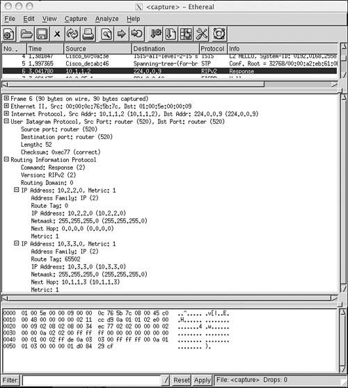
Figure 6-8 shows an analyzer capture of a RIPv2 message with authentication. The figure also shows a difficulty with the default RIP authentication: The password is transmitted in plain text. Anyone who can capture a packet containing a RIPv2 update message can read the authentication password.
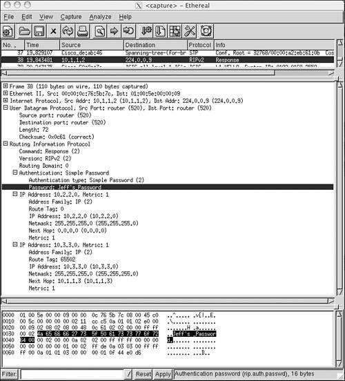
Figure 6-8. When simple password authentication is used, the password is carried in plain text and can be read by anyone who can “sniff” the packet carrying the update.
Although RFC 1723 describes only simple password authentication, foresight is shown by including the Authentication Type field. Cisco IOS takes advantage of this feature and provides the option of using MD5 authentication instead of simple password authentication.[8]
Cisco uses the first and last route entry spaces for MD5 authentication purposes.
MD5 is a one-way message digest or secure hash function, produced by RSA Data Security, Inc. It is also occasionally referred to as a cryptographic checksum because it works in somewhat the same way as an arithmetic checksum. MD5 computes a 128-bit hash value from a plain text message of arbitrary length (a RIPv2 update, for instance) and a password. This “fingerprint” is transmitted along with the message. The receiver, knowing the same password, calculates its own hash value. If nothing in the message has changed, the receiver’s hash value should match the sender’s value transmitted with the message.
Figure 6-9 shows an update from the same router of Figure 6-8, but with MD5 authentication. The authentication type is 3, and no password can be seen.
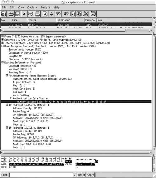
Figure 6-9. This update was originated from the same router as the update in Figure 6-8, but MD5 authentication is being used.
RIPng for IPv6 is based on RIPv2, but it is not an extension of RIPv2; it is an entirely separate protocol. RIPng does not support IPv4, so to use RIP to route both IPv4 and IPv6, you must run RIPv1 or v2 for IPv4 and RIPng for IPv6.
RIPng uses the same timers, procedures, and message types as RIPv2. For example, like RIPv2 it uses a 30-second update timer jittered to prevent message synchronization, a 180-second timeout period, a 120-second garbage-collection timer, and a 180-second holddown timer. It uses the same hop-count metric, with 16 indicating an unreachable value. And, it uses Request and Response messages in the same way that RIPv2 does. And, like RIPv2, Request and Response messages are multicast with the same few unicast exceptions that RIPv1 and v2 use. The IPv6 multicast address used by RIPng is FF02::9.
An exception to these parallel functions is authentication. RIPng does not have an authentication mechanism of its own, but instead relies on the authentication features built into IPv6.
There is, of course, no need for the RIPv1 compatibility switches used by RIPv2, because there is no backward support for IPv4.
Figure 6-10 shows the RIPng message format. Unlike RIPv1 and v2, which run at UDP port 520, RIPng sends and receives its messages at UDP port 521. Also unlike RIPv1 and v2, there is no set message size. The message size is dependent only on the MTU of the link on which it is being sent.
Command is always set to 1, indicating a Request message, or to 2, indicating a Response message.
Version is always set to 1, that is, the current version of RIPng in RIPngv1.
IPv6 Prefix is the 128-bit IPv6 destination prefix of the route entry.
Route Tag is used in the same way the 16-bit RIPv2 Route Tag field is used: for transporting external route attributes across the RIP domain.
Prefix Length is an 8-bit field specifying, in bits, the significant part of the address in the IPv6 Prefix field. For example, if the advertised prefix is 3ffe:2100:1201::/48, the value in the Prefix Length field is 48 (0x30). If the advertised route entry is a default route, the IPv6 prefix is 0:0:0:0:0:0:0:0 and the Prefix Length is 0.
Metric is the same hop count metric used by RIPv1 and v2. But as the maximum possible value is 16, the field is reduced to 8 bits from the unnecessarily large 16 bits of RIPv1 and v2.
RIPng specifies a next-hop address the same way that RIPv2 does. That is, a valid non-zero next-hop address specifies a next-hop router other than the originator of the Response message and a next-hop address of 0:0:0:0:0:0:0:0 specifies the originator of the Response message. But rather than associate a next-hop address with each route entry as RIPv2 does, RIPng specifies the next-hop address in a special route entry and then groups all route entries that use the next-hop address after it. That is, the next-hop address specified in a next-hop route entry applies to all of the route entries following it, either to the end of the Response message or until another special next-hop route entry is found.
Figure 6-11 shows the format of the next-hop route entry. The 128-bit address is either the IPv6 address of another router or, if it is ::, specifies the address of the originator. The Route Tag and Prefix Length fields are set to all zeroes. Receiving routers recognize the next-hop route entry because its Metric field is set to all ones (0xFF).

Because RIPv2 is merely an enhancement of RIPv1 and not a separate protocol, the commands introduced in Chapter 5, “Routing Information Protocol (RIP),” for manipulating timers and metrics, and for configuring unicast updates or no updates at all, are used in exactly the same way. After a brief look at configuring a RIPv2 process, the rest of this section concentrates on configuring the new extensions.
By default, a RIP process configured on a Cisco router sends only RIPv1 messages but listens to both RIPv1 and RIPv2. This default is changed with the version command, as in Example 6-1.
Example 6-1. The version 2 command causes RIP to send and listen to RIPv2 messages only.
router rip
 version 2
 network 172.25.0.0
 network 192.168.50.0
In this mode, the router sends and receives only RIPv2 messages. Likewise, the router can be configured to send and receive only RIPv1 messages, as in Example 6-2.
Example 6-2. The version 1 command causes RIP to send and listen to RIPv1 messages only.
router rip
 version 1
 network 172.25.0.0
 network 192.168.50.0
The default behavior can be restored by entering the command no version in config-router mode.
The interface-level “compatibility switches” recommended by RFC 2453 are implemented in Cisco IOS with the commands ip rip send version and ip rip receive version.
The network in Figure 6-12 contains routers speaking both RIPv1 and RIPv2. Additionally, Pojoaque is a Linux host running routed, which understands only RIPv1. The configuration of Taos is displayed in Example 6-3.
Example 6-3. Taos’s configuration.
interface Ethernet0
 ip address 192.168.50.129 255.255.255.192
 ip rip send version 1
 ip rip receive version 1
!
interface Ethernet1
 ip address 172.25.150.193 255.255.255.240
 ip rip send version 1 2
!
interface Ethernet2
 ip address 172.25.150.225 255.255.255.240
!
router rip
 version 2
 network 172.25.0.0
 network 192.168.50.0
Because router Laguna is a RIPv1 speaker, E0 of Taos is configured to send and receive RIPv1 updates. E1 is configured to send both Version 1 and 2 updates, to accommodate the RIPv1 at Pojoaque and the RIPv2 at Sandia. E2 has no special configuration; it sends and receives Version 2 by default.
In Example 6-4, debug ip rip is used to observe the messages sent and received by Taos. There are several points of interest here. First, notice the difference between the traps for RIPv1 and RIPv2 messages. The address mask and the Next Hop and Route Tag fields (both set to all zeros, in this case) of the RIPv2 updates can be observed. Second, it can be observed that interface E1 is broadcasting RIPv1 updates and multicasting RIPv2 updates. Third, because Taos has not been configured to receive RIPv1, the updates from Pojoaque (172.25.150.206) are being ignored. (Pojoaque has been misconfigured and is broadcasting its routing table.)[9]
Example 6-4. Using debugging, the RIP versions sent and received by Taos can be observed.
Taos#debug ip rip
RIP protocol debugging is on
Taos#
RIP: received v2 update from 172.25.150.194 on Ethernet1
     172.25.150.32/28 - 0.0.0.0 in 1 hops
RIP: ignored v1 packet from 172.25.150.206 (illegal version)
RIP: sending v1 update to 255.255.255.255 via Ethernet0 (192.168.50.129)
     network 172.25.0.0, metric 1
RIP: sending v1 update to 255.255.255.255 via Ethernet1 (172.25.150.193)
     subnet 172.25.150.224, metric 1
     network 192.168.50.0, metric 1
RIP: sending v2 update to 224.0.0.9 via Ethernet1 (172.25.150.193)
     172.25.150.224/28 - 0.0.0.0, metric 1, tag 0
     192.168.50.0/24 - 0.0.0.0, metric 1, tag 0
RIP: sending v2 update to 224.0.0.9 via Ethernet2 (172.25.150.225)
     172.25.150.32/28 - 0.0.0.0, metric 2, tag 0
     172.25.150.192/28 - 0.0.0.0, metric 1, tag 0
     192.168.50.0/24 - 0.0.0.0, metric 1, tag 0
RIP: received v1 update from 192.168.50.130 on Ethernet0
     192.168.50.64 in 1 hops
RIP: received v2 update from 172.25.150.194 on Ethernet1
     172.25.150.32/28 - 0.0.0.0 in 1 hops
Perhaps the most important observation to be made from Example 6-4 concerns the update being broadcast to Pojoaque: It does not include subnet 172.25.150.32. Taos knows this subnet, having learned it via multicast RIPv2 updates from Sandia. But Pojoaque cannot receive those multicasts because it speaks only RIPv1. Moreover, although Taos knows the subnet, the split horizon rule prevents Taos from advertising it out the same interface on which it was learned.
So, Pojoaque does not know about subnet 172.25.150.32. Two remedies are available: First, Sandia could be configured to send both RIP versions. Second, split horizon can be turned off at Taos’s E1 interface with the configuration in Example 6-5.
Example 6-5. Split horizon is turned off here, in Taos’s configuration.
interface Ethernet1
 ip address 172.25.150.193 255.255.255.240
 ip rip send version 1 2
 no ip split-horizon
Example 6-6 shows the results. Taos is now including subnet 172.25.150.32 in its updates. Some forethought must be given to the possible consequences of disabling split horizon; Taos is now not only advertising 172.25.150.32 to Pojoaque but also advertising it back to Sandia.
Example 6-6. With split horizon disabled on E1, Taos now includes subnet 172.25.150.32 in its updates to Pojoaque.
Taos#debug ip rip
RIP protocol debugging is on
Taos#
RIP: ignored v1 packet from 172.25.150.206 (illegal version)
RIP: received v2 update from 172.25.150.194 on Ethernet1
     172.25.150.32/28 -> 0.0.0.0 in 1 hops
RIP: sending v1 update to 255.255.255.255 via Ethernet0 (192.168.50.129)
     network 172.25.0.0, metric 1
RIP: sending v1 update to 255.255.255.255 via Ethernet1 (172.25.150.193)
     subnet 172.25.150.32, metric 2
     subnet 172.25.150.224, metric 1
     subnet 172.25.150.192, metric 1
     network 192.168.50.0, metric 1
RIP: sending v2 update to 224.0.0.9 via Ethernet1 (172.25.150.193)
     172.25.150.32/28 -> 172.25.150.194, metric 2, tag 0
     172.25.150.224/28 -> 0.0.0.0, metric 1, tag 0
     172.25.150.192/28 -> 0.0.0.0, metric 1, tag 0
192.168.50.0/24 -> 0.0.0.0, metric 1, tag 0Referring again to Figure 6-12, the subnet 172.25.150.0/24 has been assigned to the Internet shown. That subnet has been further subnetted to fit the various data links by expanding the mask to 28 bits; the available sub-subnets, in binary and dotted decimal, are shown in Table 6-2. Each of the subnets[10] will have, according to the 2n – 2 formula, 14 host addresses. Out of these, 172.25.150.32, 172.25.150.192, and 172.25.150.224 have been used.
Table 6-2. VLSM is applied to subnet 172.25.150.0/24.
Binary Representation | Dotted Decimal |
|---|---|
11111111111111111111111111110000 | 255.255.255.240 |
10101100000110011001011000000000 | 172.25.150.0/28 |
10101100000110011001011000010000 | 172.25.150.16/28 |
10101100000110011001011000100000 | 172.25.150.32/28 |
10101100000110011001011000110000 | 172.25.150.48/28 |
10101100000110011001011001000000 | 172.25.150.64/28 |
10101100000110011001011001010000 | 172.25.150.80/28 |
10101100000110011001011001100000 | 172.25.150.96/28 |
10101100000110011001011001110000 | 172.25.150.112/28 |
10101100000110011001011010000000 | 172.25.150.128/28 |
10101100000110011001011010010000 | 172.25.150.144/28 |
10101100000110011001011010100000 | 172.25.150.160/28 |
10101100000110011001011010110000 | 172.25.150.176/28 |
10101100000110011001011011000000 | 172.25.150.192/28 |
10101100000110011001011011010000 | 172.25.150.208/28 |
10101100000110011001011011100000 | 172.25.150.224/28 |
10101100000110011001011011110000 | 172.25.150.240/28 |
In Figure 6-13, a new Ethernet segment, Ethernet 3, has been added to Taos, with 60 hosts. A subnet with at least six host bits is required to accommodate this data link. A classful routing protocol would require that five of the subnets from Table 6-2 be assigned to Ethernet 3 [5 × (24 – 2) = 70], using secondary addresses. With classless protocols and VLSM, four of the subnets from Table 6-2 can be combined into a single subnet with a 26-bit mask. This step will provide six host bits (62 host addresses), and no secondary addressing is necessary. Four subnets, 172.25.150.64/28 to 172.25.150.112/28, are combined under one 26-bit mask: 172.25.150.64/26. Notice that the four subnets are not selected at random; the first 26 masked bits are identical and are unique within the group of 16 subnets.[11]
Also, in Figure 6-13, four serial links and four routers have been added to the network. Without VLSM, four of the subnets from Table 6-2 would have to be used for the four serial links. With VLSM, a single subnet from Table 6-2 can be used for all four serial links. 172.25.150.240 is selected, and a 30-bit mask is used to create the subnets in Table 6-3. Each of the resulting four subnets contains two host addresses.
Table 6-3. A 30-bit mask is applied to subnet 172.25.150.240.
Binary Representation | Dotted Decimal |
|---|---|
11111111111111111111111111111100 | 255.255.255.252 |
10101100000110011001011011110000 | 172.25.150.240/30 |
10101100000110011001011011110100 | 172.25.150.244/30 |
10101100000110011001011011111000 | 172.25.150.248/30 |
10101100000110011001011011111100 | 172.25.150.252/30 |
The fundamental objective of subnetting is always the same: A router must be able to identify every data link with a unique address, distinct from any other address in the network. That is the common goal in the preceding two examples. In the first example, multiple addresses were combined into a single address by reducing the size of the mask until only the bits common to all of the addresses remain. Note that this result also happens when subnets are summarized by the major network address. In the second example, multiple subnets were created from a single subnet by expanding the subnet mask.
Figure 6-14 shows that two Ethernets are connected to each of the four new routers. At each site, one Ethernet is a member of subnet 172.25.150.0/24 and will have no more than 12 hosts. This is easy enough. Four unused subnets are chosen from Table 6-2 and assigned.

Figure 6-14. Cochiti, Isleta, Jemez, and Tesuque are each attached to two Ethernets. One Ethernet at each router is a member of subnet 172.25.150.0/24, and the other is a member of network 192.168.50.0/24.
The other Ethernet at each site is a member of network 192.168.50.0 and will have no more than 25 hosts. Subnets 192.168.50.64/26 and 192.168.50.128/26 are being used, which leaves 192.168.50.0/26 and 192.168.50.192/26. By increasing the mask to 27 bits, these two subnets can be divided into four, each with five host bits—enough for 30 host addresses per subnet. Table 6-4 shows the four subnets in binary.
Having assigned all subnet addresses, the next concern is the fact that the subnets of 192.168.50.0 are discontiguous. Chapter 5 presents a case study on discontiguous subnets and demonstrates how to use secondary interfaces to connect them. Classless routing protocols have no such difficulties with discontiguous subnets. Because each route update includes a mask, subnets of one major network can be advertised into another major network.
The default behavior of RIPv2, however, is to summarize at network boundaries the same as RIPv1. To turn off summarization and allow subnets to be advertised across network boundaries, use the command no auto-summary with the RIP process. The configuration for Cochiti is displayed in Example 6-7.
Example 6-7. Cochiti’s configuration with no automatic summarization.
interface Ethernet0
 ip address 192.168.50.1 255.255.255.224
!
interface Ethernet1
 ip address 172.25.150.1 255.255.255.240
!
interface Serial0
 ip address 172.25.150.242 255.255.255.252
!
router rip
 version 2
 network 172.25.0.0
 network 192.168.50.0
 no auto-summary
Isleta, Jemez, and Tesuque will have similar configurations. Summarization must also be turned off at Taos and at Acoma. Recall from Figure 6-12 that Laguna was running RIPv1. For this configuration to work, it must be changed to Version 2.
Careful consideration should be given to what effect the variable masks will have on Pojoaque, where RIPv1 continues to run. The debug messages in Example 6-8 show the Version 1 and Version 2 updates sent from Taos onto subnet 172.25.150.192/28. The Version 1 updates will include only those subnets whose masks are 28 bits, the same as the subnet on which the updates are being broadcast. Although Pojoaque will not receive advertisements for 172.25.150.64/26 or any of the serial link subnets, an analysis of those subnet addresses shows that Pojoaque will, in this case, correctly interpret the addresses as being different from its own subnet. Packets destined for these subnets will be sent to Taos for routing.
Example 6-8. Although the RIPv2 update from Taos includes all subnets in the network, the RIPv1 update includes only a summary route to network 192.168.50.0 and only those subnets of 172.25.150.0 whose masks are the same as the interface on which the update is being sent.
Taos#debug ip rip
RIP protocol debugging is on
RIP: sending v1 update to 255.255.255.255 via Ethernet0 (172.25.150.193)
     subnet 172.25.150.0, metric 3
     subnet 172.25.150.16, metric 3
     subnet 172.25.150.32, metric 2
     subnet 172.25.150.48, metric 3
     subnet 172.25.150.128, metric 3
     subnet 172.25.150.192, metric 1
     subnet 172.25.150.224, metric 1
     network 192.168.50.0, metric 1
RIP: sending v2 update to 224.0.0.9 via Ethernet0 (172.25.150.193)
     172.25.150.0/28 -> 0.0.0.0, metric 3, tag 0
     172.25.150.16/28 -> 0.0.0.0, metric 3, tag 0
     172.25.150.32/28 -> 0.0.0.0, metric 2, tag 0
     172.25.150.48/28 -> 0.0.0.0, metric 3, tag 0
     172.25.150.64/26 -> 0.0.0.0, metric 1, tag 0
     172.25.150.128/28 -> 0.0.0.0, metric 3, tag 0
     172.25.150.192/28 -> 0.0.0.0, metric 1, tag 0
     172.25.150.224/28 -> 0.0.0.0, metric 1, tag 0
     172.25.150.240/30 -> 0.0.0.0, metric 2, tag 0
     172.25.150.244/30 -> 0.0.0.0, metric 2, tag 0
     172.25.150.248/30 -> 0.0.0.0, metric 2, tag 0
     172.25.150.252/30 -> 0.0.0.0, metric 2, tag 0
     192.168.50.0/27 -> 0.0.0.0, metric 3, tag 0
     192.168.50.32/27 -> 0.0.0.0, metric 3, tag 0
     192.168.50.64/26 -> 0.0.0.0, metric 2, tag 0
     192.168.50.128/26 -> 0.0.0.0, metric 1, tag 0
     192.168.50.192/27 -> 0.0.0.0, metric 3, tag 0
192.168.50.224/27 -> 0.0.0.0, metric 3, tag 0The Cisco implementation of RIPv2 message authentication includes the choice of simple password or MD5 authentication, and the option of defining multiple keys, or passwords, on a “key chain.” The router may then be configured to use different keys at different times.
The steps for setting up RIPv2 authentication follow:
In Example 6-9, a key chain named Tewa is configured at Taos. Key 1, the only key on the chain, has a password of Kachina; interface E0 then uses the key, with MD5 authentication, to validate updates from Laguna.
Example 6-9. Taos’s authentication configuration.
key chain Tewa
 key 1
 key-string Kachina
interface Ethernet 0
 ip rip authentication key-chain Tewa
 ip rip authentication mode md5
A key chain must be configured, even if there is only one key on it. Although any routers that will exchange authenticated updates must have the same password, the name of the key chain has significance only on the local router. Laguna, for instance, might have a key chain named Keres, but the key string must be Kachina to speak to Taos.
If the command ip rip authentication mode md5 is not added, the interface will use the default clear text authentication. Although clear text authentication may be necessary to communicate with some RIPv2 implementations, it is almost always wise to use the far more secure MD5 authentication whenever possible.
Key management is used to migrate from one authentication key to another. In Example 6-10, Laguna is configured to begin using the first key at 4:30 p.m. on July 1, 2004, for 12 hours (43200 seconds). The second key becomes valid at 4:00 a.m. on July 2, 2004, and will be used until 1:00 p.m. on December 31, 2004. The third key becomes valid at 12:30 p.m. on December 31, 2004, and will remain valid permanently after that.
Example 6-10. Laguna’s authentication configuration.
key chain Keres
 key 1
  key-string Kachina
  accept-lifetime 16:30:00 Jul 1 2004 duration 43200
  send-lifetime 16:30:00 Jul 1 2004 duration 43200
 key 2
  key-string Kiva
  accept-lifetime 04:00:00 Jul 2 2004 13:00:00 Dec 31 2004
  send-lifetime 04:00:00 Jul 2 2004 13:00:00 Dec 31 2004
 key 3
  key-string Koshare
  accept-lifetime 12:30:00 Dec 31 2004 infinite
  send-lifetime 12:30:00 Dec 31 2004 infinite
!
interface Ethernet0
 ip address 198.168.50.130 255.255.255.192
 ip rip authentication key-chain Keres
 ip rip authentication mode md5
As the configuration shows, the password that is accepted from other routers and the password that is used with transmitted messages are managed separately. Both the accept-lifetime and the send-lifetime commands must have a specified start time and may have either a specified duration or end time or the keyword infinite. The key numbers are examined from the lowest to the highest, and the first valid key is used.
Although this configuration uses a 30-minute overlap to compensate for differences in system times, it is highly recommended that a time synchronization protocol such as Network Time Protocol (NTP) be used with key management.[12]
The steps for configuring RIPng are the same as RIPv1 and v2: Create the routing process, enable the routing protocol on interfaces, and perform any desired customization. The commands, however, are very different. In fact, the creation of the routing process and enabling the routing protocol on the first interface is accomplished in one step, using an interface command. The case studies for RIPng will be similar to those of RIPv1 and v2 to illustrate the similarities in the processes and the differences in configuration.
After IPv6 unicast routing is enabled on the router, only one command is required to enable RIPng for IPv6 routing. It is an interface command: ipv6 rip process-name enable. This creates the RIPng process called process-name and enables RIPng on the interface at the same time. The command is entered on each interface that will run RIPng.
Figure 6-15 shows that IPv6, RIPng, and some new Ethernet interfaces have been added to a portion of the network in Figure 6-14.

Figure 6-15. IPv6 addresses are configured on Laguna, Taos, and Sandia’s interfaces that are to run RIPng.
Example 6-11 shows Taos’s configuration.
Example 6-11. Taos’s IPv6 and RIPng configuration.
ipv6 unicast-routing
interface Ethernet0
 ipv6 address 2001:db8:0:6::1/64
 ipv6 rip bigMountain enable

interface Ethernet1
 ipv6 address 2001:db8:0:4::1/64
 ipv6 rip bigMountain enable

interface Ethernet2
 ipv6 address 2001:db8:0:5::1/64
 ipv6 rip bigMountain enable
The RIPng process is created and activated on an interface with a single interface command. This is the difference between configuring RIPv1 and v2, and configuring RIPng. Recall that the RIPv1 and v2 configuration requires a global command (router rip) to create the process, and the network <address> statement to specify the interfaces on which to run the RIP process. With RIPng, when the interface command ipv6 rip bigMountain enable is configured on the first interface, the RIPng process called bigMountain is automatically created. In addition, IOS automatically creates an entry in the configuration (ipv6 router rip bigMountain) for the routing process.
The process name specified on Taos is bigMountain. Notice that the process name is specified on each interface. This name is relevant only to the local router, and is used to distinguish between multiple RIPng processes that might be running on the router. Different interfaces can each run a unique RIPng process, without exchanging information between these interfaces, or multiple processes might be running on a single interface. Only a single RIPv1 or RIPv2 process, on the other hand, can run on a router, and an interface either belongs to this process, or it doesn’t run RIP.[13]
Example 6-12 shows Sandia’s IPv6 route table. All the addresses in the network are listed because Taos is configured with a single RIPng process on each of its IPv6 interfaces.
Example 6-12. Taos’s IPv6 route table.
Sandia#show ipv6 route
IPv6 Routing Table - 16 entries
Codes: C - Connected, L - Local, S - Static, R - RIP, B – BGP
       U - Per-user Static route
       I1 - ISIS L1, I2 - ISIS L2, IA - ISIS interarea, IS - ISIS summary
       O - OSPF intra, OI - OSPF inter, OE1 - OSPF ext 1, OE2 - OSPF ext 2
       ON1 - OSPF NSSA ext 1, ON2 - OSPF NSSA ext 2
C   2001:DB8:0:4::/64 [0/0]
     via ::, Ethernet0
L   2001:DB8:0:4::2/128 [0/0]
     via ::, Ethernet0
R   2001:DB8:0:5::/64 [120/2]
     via FE80::205:5EFF:FE6B:50A1, Ethernet0
R   2001:DB8:0:6::/64 [120/2]
     via FE80::205:5EFF:FE6B:50A1, Ethernet0
C   2001:DB8:0:10::/64 [0/0]
     via ::, Ethernet1
L   2001:DB8:0:10:2B0:64FF:FE30:1DE0/128 [0/0]
     via ::, Ethernet1
C   2001:DB8:0:11::/64 [0/0]
     via ::, Ethernet2
L   2001:DB8:0:11:2B0:64FF:FE30:1DE0/128 [0/0]
     via ::, Ethernet2
C   2001:DB8:0:12::/64 [0/0]
     via ::, Ethernet3
L   2001:DB8:0:12:2B0:64FF:FE30:1DE0/128 [0/0]
     via ::, Ethernet3
C   2001:DB8:0:13::/64 [0/0]
     via ::, Ethernet4
L   2001:DB8:0:13:2B0:64FF:FE30:1DE0/128 [0/0]
     via ::, Ethernet4
R   2001:DB8:0:18::/64 [120/3]
     via FE80::205:5EFF:FE6B:50A1, Ethernet0
L   FE80::/10 [0/0]
     via ::, Null0
L   FF00::/8 [0/0]
     via ::, Null0
Two new Ethernet interfaces have been added to Acoma, as shown in Figure 6-16. New network policy states that IPv6 traffic in the network of Figure 6-16 should be segmented according to the following policy: Hosts on the LANs connected to Sandia access each other, and they also access devices on Ethernet1 connected to Acoma. Hosts connected to the Laguna router access the devices on Ethernet2 of Acoma. Sandia and Laguna hosts do not need to access each other. Acoma Ethernet1 and Ethernet 2 do not access each other.
The configuration in Example 6-13 is loaded into Taos.
Example 6-13. Taos’s configuration to support network policy to segment IPv6 network traffic by creating multiple RIPng routing processes.
Interface Ethernet0
 ipv6 rip bigMountain enable
Interface Ethernet1
 no ipv6 rip bigMountain enable
 ipv6 rip smallMountain enable
interface Ethernet2
 ipv6 rip bigMountain enable
 ipv6 rip smallMountain enable

ipv6 router rip smallMountain
 port 527 multicast ff02::9
Interface Ethernet 0, the link to Laguna, still belongs to the bigMountain RIPng process. A new process, smallMountain, is now enabled on Ethernet 1, the link to Sandia, and bigMountain has been disabled on the interface. Both processes are enabled on Ethernet2, connecting to Acoma. No two RIPng routing processes can use the same UDP port number if both processes are going to be active on a single interface. By changing the port number on the smallMountain process, Taos sends updates for smallMountain to UDP port 527, and updates for the bigMountain process to the default RIPng port, UDP 521. Receiving routers use the port number to distinguish which routing process a received update belongs to. A RIPng router running a single routing process, receiving updates from more then one RIPng process running on a router using identical UDP port numbers, will process each update. If there is conflicting information about an address in both updates, such as a differing metric, the receiving route table may be changing with each update. If a receiving router is running multiple RIPng processes and the same UDP port number is used on both, the receiving router will not be able to distinguish which RIPng process should receive the update. Changing the UDP port number on the second and subsequent RIPng process eliminates these problems. All routers and hosts that need to participate in the RIPng process with the modified UDP port number must use the same UDP port number. Because routers and other TCP/IP devices use port numbers identify which UDP process the packets need to be forwarded to, and RIPng updates are multicast to all RIPng routers, the new UDP port number must not be the same as any other process running on any RIPng router. The smallMountain process is configured to use port 527 in this example. The port number must be changed on the routers exchanging RIPng updates with the smallMountain RIPng process. Sandia and Acoma’s configuration changes follow in Example 6-14 and Example 6-15, respectively.
Example 6-14. Sandia’s RIPng configuration with a modified UDP port number.
ipv6 router rip smallMountain
  port 527 multicast-group FF02::9
Example 6-15. Acoma’s RIPng configuration with a modified UDP port number.
interface Ethernet0
 ipv6 address 2001:DB8:0:5::2/64
 ipv6 rip hill enable
 ipv6 rip summit enable
interface Ethernet1
 ipv6 address 2001:DB8:0:20::/64
 ipv6 rip hill enable
interface Ethernet2
 ipv6 address 2001:DB8:0:21::/64
 ipv6 rip summit enable
ipv6 router rip hill
  port 527 multicast-group FF02::9
Notice that the process names on Acoma are not the same as those on Taos. RIPng process names are relevant only to the local router. They are not exchanged in route updates. Acoma’s Ethernet0 is connected to Taos’s Ethernet2. It is running two routing processes: hill and summit. hill is also running on interface Ethernet1. Ethernet1’s IPv6 address is advertised to Taos using the modified UDP port number 527. This is associated with the smallMountain RIPng process on Taos, and therefore, the IPv6 address gets advertised to Sandia, not Laguna.
Example 6-16 displays information about the RIPng routing processes running on Taos. The command show ipv6 rip displays each process individually. Notice that the default maximum number of parallel paths is 16, and the timer values have not been modified from the default.
Example 6-16. show ipv6 rip displays information about each RIPng process running on a router.
Taos#show ipv6 rip
RIP process "bigMountain", port 521, multicast-group FF02::9, pid 104
     Administrative distance is 120. Maximum paths is 16
     Updates every 30 seconds, expire after 180
     Holddown lasts 0 seconds, garbage collect after 120
     Split horizon is on; poison reverse is off
     Default routes are not generated
     Periodic updates 1078, trigger updates 5
  Interfaces:
    Ethernet2
    Ethernet0
  Redistribution:
    None
RIP process "smallMountain", port 527, multicast-group FF02::9, pid 117
     Administrative distance is 120. Maximum paths is 16
     Updates every 30 seconds, expire after 180
     Holddown lasts 0 seconds, garbage collect after 120
     Split horizon is on; poison reverse is off
     Default routes are not generated
     Periodic updates 1080, trigger updates 5
  Interfaces:
    Ethernet1
    Ethernet2
  Redistribution:
    None
The process bigMountain is running on interfaces Ethernet0 and Ethernet2. Interfaces Ethernet1 and Ethernet2 belong to the smallMountain process, using UDP port number 527.
The IPv6 route table shows that Taos has installed routes from both processes into its route table (Example 6-17).
Example 6-17. IPv6 route table displays all known routes from each active RIPng process.
Taos#show ipv6 route
IPv6 Routing Table - 15 entries
Codes: C - Connected, L - Local, S - Static, R - RIP, B – BGP
       U - Per-user Static route
       I1 - ISIS L1, I2 - ISIS L2, IA - ISIS interarea, IS - ISIS summary
       O - OSPF intra, OI - OSPF inter, OE1 - OSPF ext 1, OE2 - OSPF ext 2
       ON1 - OSPF NSSA ext 1, ON2 - OSPF NSSA ext 2
C   2001:DB8:0:4::/64 [0/0]
     via ::, Ethernet1
L   2001:DB8:0:4::1/128 [0/0]
     via ::, Ethernet1
C   2001:DB8:0:5::/64 [0/0]
     via ::, Ethernet2
L   2001:DB8:0:5::1/128 [0/0]
     via ::, Ethernet2
C   2001:DB8:0:6::/64 [0/0]
     via ::, Ethernet0
L   2001:DB8:0:6::1/128 [0/0]
     via ::, Ethernet0
R   2001:DB8:0:10::/64 [120/2]
     via FE80::2B0:64FF:FE30:1DE0, Ethernet1
R   2001:DB8:0:11::/64 [120/2]
     via FE80::2B0:64FF:FE30:1DE0, Ethernet1
R   2001:DB8:0:12::/64 [120/2]
     via FE80::2B0:64FF:FE30:1DE0, Ethernet1
R   2001:DB8:0:13::/64 [120/2]
     via FE80::2B0:64FF:FE30:1DE0, Ethernet1
R   2001:DB8:0:18::/64 [120/2]
     via FE80::204:C1FF:FE50:F1C0, Ethernet0
R   2001:DB8:0:20::/64 [120/2]
     via FE80::204:C1FF:FE50:E700, Ethernet2
R   2001:DB8:0:21::/64 [120/2]
     via FE80::204:C1FF:FE50:E700, Ethernet2
L   FE80::/10 [0/0]
     via ::, Null0
L   FF00::/8 [0/0]
     via ::, Null0
Taking a look at Laguna and Sandia’s route tables in Example 6-18 and Example 6-19, you can see that each router learns about the routes belonging to the appropriate RIPng process. Taos does not forward smallMountain addresses into the bigMountain process, and vice versa.
Example 6-18. IPv6 route table displays Laguna’s routes learned from the bigMountain RIPng process on Taos.
Laguna#show ipv6 route rip
IPv6 Routing Table - 8 entries
Codes: C - Connected, L - Local, S - Static, R - RIP, B – BGP
       U - Per-user Static route
       I1 - ISIS L1, I2 - ISIS L2, IA - ISIS interarea, IS - ISIS summary
       O - OSPF intra, OI - OSPF inter, OE1 - OSPF ext 1, OE2 - OSPF ext 2
       ON1 - OSPF NSSA ext 1, ON2 - OSPF NSSA ext 2
R   2001:DB8:0:5::/64 [120/2]
     via FE80::205:5EFF:FE6B:50A0, Ethernet0
R   2001:DB8:0:21::/64 [120/3]
     via FE80::205:5EFF:FE6B:50A0, Ethernet0
Example 6-19. IPv6 route table displays Sandia’s routes learned from the smallMountain RIPng process on Taos.
Sandia#show ipv6 route rip
IPv6 Routing Table - 14 entries
Codes: C - Connected, L - Local, S - Static, R - RIP, B – BGP
       U - Per-user Static route
       I1 - ISIS L1, I2 - ISIS L2, IA - ISIS interarea, IS - ISIS summary
       O - OSPF intra, OI - OSPF inter, OE1 - OSPF ext 1, OE2 - OSPF ext 2
       ON1 - OSPF NSSA ext 1, ON2 - OSPF NSSA ext 2
R   2001:DB8:0:5::/64 [120/2]
     via FE80::205:5EFF:FE6B:50A1, Ethernet0
R   2001:DB8:0:20::/64 [120/3]
     via FE80::205:5EFF:FE6B:50A1, Ethernet0
Example 6-17 shows that Taos has learned four addresses from Sandia on Ethernet1, which belongs to the smallMountain RIPng process: 2001:db8:0:10::/64, 2001:db8:0:11::/64, 2001:db8:0:12::/64, and 2001:db8:0:13::/64. 2001:db8:0:5::/64, connected to Ethernet2, is advertised into both the smallMountain and the bigMountain processes. Laguna’s route table in Example 6-18 shows that no smallMountain routes have been installed.
Debugging RIPng on Taos (Example 6-20) shows the RIPng updates that are sent out and received into each interface for each process.
Example 6-20. debug ipv6 rip displays the RIPng updates on each interface for each active process.
Taos#debug ipv6 rip
RIP Routing Protocol debugging is on
Taos#
RIPng: Sending multicast update on Ethernet2 for bigMountain
        src=FE80::205:5EFF:FE6B:50A0
        dst=FF02::9 (Ethernet2)
        sport=521, dport=521, length=72
        command=2, version=1, mbz=0, #rte=3
        tag=0, metric=1, prefix=2001:DB8:0:5::/64
        tag=0, metric=1, prefix=2001:DB8:0:6::/64
        tag=0, metric=2, prefix=2001:DB8:0:18::/64
RIPng: Sending multicast update on Ethernet0 for bigMountain
        src=FE80::205:5EFF:FE6B:50A0
        dst=FF02::9 (Ethernet0)
        sport=521, dport=521, length=72
        command=2, version=1, mbz=0, #rte=3
        tag=0, metric=1, prefix=2001:DB8:0:5::/64
        tag=0, metric=1, prefix=2001:DB8:0:6::/64
        tag=0, metric=2, prefix=2001:DB8:0:21::/64
RIPng: response received from FE80::2B0:64FF:FE30:1DE0 on Ethernet1 for
  smallMountain
        src=FE80::2B0:64FF:FE30:1DE0 (Ethernet1)
        dst=FF02::9
        sport=527, dport=527, length=112
        command=2, version=1, mbz=0, #rte=5
        tag=0, metric=1, prefix=2001:DB8:0:4::/64
        tag=0, metric=1, prefix=2001:DB8:0:10::/64
        tag=0, metric=1, prefix=2001:DB8:0:11::/64
        tag=0, metric=1, prefix=2001:DB8:0:12::/64
        tag=0, metric=1, prefix=2001:DB8:0:13::/64
RIPng: response received from FE80::204:C1FF:FE50:E700 on Ethernet2 for
  smallMountain
        src=FE80::204:C1FF:FE50:E700 (Ethernet2)
        dst=FF02::9
        sport=527, dport=527, length=52
        command=2, version=1, mbz=0, #rte=2
        tag=0, metric=1, prefix=2001:DB8:0:5::/64
        tag=0, metric=1, prefix=2001:DB8:0:20::/64
RIPng: response received from FE80::204:C1FF:FE50:F1C0 on Ethernet0 for bigMountain
        src=FE80::204:C1FF:FE50:F1C0 (Ethernet0)
        dst=FF02::9
        sport=521, dport=521, length=52
        command=2, version=1, mbz=0, #rte=2
        tag=0, metric=1, prefix=2001:DB8:0:6::/64
        tag=0, metric=1, prefix=2001:DB8:0:18::/64
RIPng: response received from FE80::204:C1FF:FE50:E700 on Ethernet2 for bigMountain
        src=FE80::204:C1FF:FE50:E700 (Ethernet2)
        dst=FF02::9
        sport=521, dport=521, length=52
        command=2, version=1, mbz=0, #rte=2
        tag=0, metric=1, prefix=2001:DB8:0:5::/64
        tag=0, metric=1, prefix=2001:DB8:0:21::/64
RIPng: Sending multicast update on Ethernet1 for smallMountain
        src=FE80::205:5EFF:FE6B:50A1
        dst=FF02::9 (Ethernet1)
        sport=527, dport=527, length=72
        command=2, version=1, mbz=0, #rte=3
        tag=0, metric=1, prefix=2001:DB8:0:4::/64
        tag=0, metric=1, prefix=2001:DB8:0:5::/64
        tag=0, metric=2, prefix=2001:DB8:0:20::/64
RIPng: Sending multicast update on Ethernet2 for smallMountain
        src=FE80::205:5EFF:FE6B:50A0
        dst=FF02::9 (Ethernet2)
        sport=527, dport=527, length=132
        command=2, version=1, mbz=0, #rte=6
        tag=0, metric=1, prefix=2001:DB8:0:4::/64
        tag=0, metric=1, prefix=2001:DB8:0:5::/64
        tag=0, metric=2, prefix=2001:DB8:0:10::/64
        tag=0, metric=2, prefix=2001:DB8:0:11::/64
        tag=0, metric=2, prefix=2001:DB8:0:12::/64
        tag=0, metric=2, prefix=2001:DB8:0:13::/64
smallMountain updates are sent out Ethernet1, to Sandia, and Ethernet2, to Acoma. bigMountain updates are sent out Ethernet0, to Laguna, and Ethernet2, to Acoma. Two updates are received on Ethernet2 from Acoma. One uses the default UDP port 521. The other uses UDP port 527, the UDP port associated with smallMountain. The update that uses port 527 includes the prefix 2001:DB8:0:20::/64. This is the prefix assigned to Ethernet1 on Acoma, the prefix which Sandia is permitted to access. The update received on Ethernet2 using UDP port 521 includes prefix 2001:DB8:0:21::/64. This prefix is assigned to Ethernet2 on Acoma and is distributed into the bigMountain process on Taos, and sent to Laguna.
Some customization to the routing process is achieved in a way similar to RIPv1 and v2. The global configuration command ipv6 router rip process_name lets you configure global parameters to that RIPng process.
The administrative distance, the maximum number of paths the routing process will use for load sharing, and RIP timers were discussed in Chapter 5. These parameters are used the same way for RIPng as they are for RIPv1 and v2. RIPng’s default administrative distance is 120, the same as RIPv1 and v2. The default maximum number of paths over which RIPng will load share is 16. RIPng can load share on up to 64 paths. The timer parameters, although not all the values, are the same as for RIPv1 and v2: update every 30 seconds, expire after 180 seconds, holddown is 0, garbage collection is 120 seconds.
A configuration for Taos that modifies the distance, maximum-paths, and timers is shown in Example 6-21.
Example 6-21. Taos’s configuration modifies the administrative distance, the maximum number of paths for load sharing, and the protocol times.
ipv6 router rip bigMountain
  timers 10 30 30 60
  maximum-paths 8
  distance 200
Example 6-22 shows the output of show ipv6 rip and displays the new parameter values.
Example 6-22. The show ipv6 rip command on Taos shows the modified RIPng values.
Taos#show ipv6 rip
RIP process "bigMountain", port 521, multicast-group FF02::9, pid 104
     Administrative distance is 200. Maximum paths is 8
     Updates every 10 seconds, expire after 30
     Holddown lasts 30 seconds, garbage collect after 60
     Split horizon is on; poison reverse is off
     Default routes are not generated
     Periodic updates 2513, trigger updates 7
  Interfaces:
    Ethernet2
    Ethernet0
  Redistribution:
    None
RIP process "smallMountain", port 527, multicast-group FF02::9, pid 122
     Administrative distance is 120. Maximum paths is 16
     Updates every 30 seconds, expire after 180
     Holddown lasts 0 seconds, garbage collect after 120
     Split horizon is on; poison reverse is off
     Default routes are not generated
     Periodic updates 2511, trigger updates 0
  Interfaces:
    Ethernet2
    Ethernet1
  Redistribution:
    None
Taos#
Compare the values in the bigMountain process with those in the smallMountain process, which still has the default values. Be careful modifying the timers and the administrative distance. All routers running the same RIPng process must have the same timer values. The administrative distance is only relevant to the local router, but consider carefully the consequence of changing the administrative distance if multiple routing protocols or routing processes are running on the router and addresses are being learned from multiple routing processes. Changing the administrative distance changes the degree of preference for the routing process. An address learned via a process with a lower distance will get inserted into the routing table. If the same address is learned via a higher administrative distance process, the address will get inserted into the routing table only if the first entry fails. The configuration in Example 6-23 changes the values back to the defaults.
As with RIPv1 and v2, RIPng metrics are adjusted by adding an offset. RIPng does not, however, increment the metrics of each entry in a list of prefixes. RIPng modifies the hop count that is associated with an interface. This increments the metric of every prefix that is advertised to the router via this interface by the amount of the hop count configured on the interface. By default, RIPng adds a single hop to the metric of prefixes advertised by a neighboring router. Example 6-24 shows the RIPng route table on Taos and a RIPng update received from Sandia. Notice that each of the metrics in the route table has a value of two. Each RIPng route in the table is directly connected to a router that is one hop away, either Sandia or Laguna. Sandia and Laguna advertise their prefixes with a metric of one. Taos adds a hop count of one to each of the received metrics. To change the value that Taos adds to the received metric, use the metric-offset command, as in Example 6-25.
Example 6-24. RIPng route table and debug ipv6 rip showing a received update illustrates the metric offset added to a received metric.
Taos#show ipv6 route rip
IPv6 Routing Table - 15 entries
Codes: C - Connected, L - Local, S - Static, R - RIP, B – BGP
       U - Per-user Static route
       I1 - ISIS L1, I2 - ISIS L2, IA - ISIS interarea, IS - ISIS summary
       O - OSPF intra, OI - OSPF inter, OE1 - OSPF ext 1, OE2 - OSPF ext 2
       ON1 - OSPF NSSA ext 1, ON2 - OSPF NSSA ext 2
R   2001:db8:0:18::/64[120/2]
     via FE80::204:C1FF:FE50:F1C0, Ethernet0
R   2001:db8:0:10::/64 [120/2]
     via FE80::2B0:64FF:FE30:1DE0, Ethernet1
R   2001:db8:0:11::/64 [120/2]
     via FE80::2B0:64FF:FE30:1DE0, Ethernet1
R   2001:db8:0:12::/64 [120/2]
     via FE80::2B0:64FF:FE30:1DE0, Ethernet1
R   2001:db8:0:13::/64 [120/2]
     via FE80::2B0:64FF:FE30:1DE0, Ethernet1
R   2001:DB8:0:20::/64 [120/2]
     via FE80::204:C1FF:FE50:E700, Ethernet2
R   2001:DB8:0:21::/64 [120/2]
     via FE80::204:C1FF:FE50:E700, Ethernet2
Taos#debug ipv6 rip
RIP Routing Protocol debugging is on
   RIPng: response received from FE80::2B0:64FF:FE30:1DE0 on Ethernet1 for
     smallMountain
        src=FE80::2B0:64FF:FE30:1DE0 (Ethernet1)
        dst=FF02::9
        sport=521, dport=521, length=112
        command=2, version=1, mbz=0, #rte=4
        tag=0, metric=1, prefix=2001:db8:0:10::/64
        tag=0, metric=1, prefix=2001:db8:0:11::/64
        tag=0, metric=1, prefix=2001:db8:0:12::/64
        tag=0, metric=1, prefix=2001:db8:0:13::/64
Example 6-25. The RIPng metric-offset is increased to three on Taos’s Ethernet1 interface.
interface Ethernet1
 ipv6 rip smallMountain metric-offset 3
Example 6-26 shows the new route table on Taos. Taos has added a hop count of 3 to each of the prefixes the router received on Ethernet1.
Example 6-26. RIPng route table after the metric offset has been modified on the receiving interface shows a higher metric value for each prefix learned via the modified interface.
Taos#show ipv6 route rip
IPv6 Routing Table - 15 entries
Codes: C - Connected, L - Local, S - Static, R - RIP, B – BGP
       U - Per-user Static route
       I1 - ISIS L1, I2 - ISIS L2, IA - ISIS interarea, IS - ISIS summary
       O - OSPF intra, OI - OSPF inter, OE1 - OSPF ext 1, OE2 - OSPF ext 2
       ON1 - OSPF NSSA ext 1, ON2 - OSPF NSSA ext 2
R   2001:DB8:0:10::/64 [120/4]
     via FE80::2B0:64FF:FE30:1DE0, Ethernet1
R   2001:DB8:0:11::/64 [120/4]
     via FE80::2B0:64FF:FE30:1DE0, Ethernet1
R   2001:DB8:0:12::/64 [120/4]
     via FE80::2B0:64FF:FE30:1DE0, Ethernet1
R   2001:DB8:0:13::/64 [120/4]
     via FE80::2B0:64FF:FE30:1DE0, Ethernet1
R   2001:DB8:0:18::/64 [120/2]
     via FE80::204:C1FF:FE50:F1C0, Ethernet0
R   2001:DB8:0:20::/64 [120/2]
     via FE80::204:C1FF:FE50:E700, Ethernet2
R   2001:DB8:0:21::/64 [120/2]
     via FE80::204:C1FF:FE50:E700, Ethernet2
This command allows you to adjust the hop count associated with a given link. All addresses received by the adjusted interface will have the adjusted metric. By contrast, RIPv1 and v2 allow you to add the offset to a subset (or all) of the addresses received by the interface before they are added to the route table, or the offset can be added to the addresses just before they are advertised out of the interface.
As with RIPv2, RIPng routes can be summarized before they are advertised to neighbors. Sandia advertises routes for 2001:DB8:0:10::/64, 2001:DB8:0:11::/64, 2001:DB8:0:12::/64, and 2001:DB8:0:13::/64. The routes can be summarized into a single entry: 2001:DB8: 0:10::/62. Sandia’s configuration is in Example 6-27.
Example 6-27. Sandia is configured to summarize advertised RIPng addresses.
interface Ethernet0
 ipv6 address 2001:DB8:0:4::2/64
 ipv6 rip bigMountain enable
 ipv6 rip bigMountain summary-address 2001:DB8:0:10::/62
The more specific prefixes are automatically suppressed when an encompassing summary address is configured. Example 6-28 shows Taos’s new route table.
Example 6-28. Four consecutive prefixes with a length of 64 bits have been summarized into a single entry with a length of 62 bits.
Taos#show ipv6 route rip
IPv6 Routing Table - 12 entries
Codes: C - Connected, L - Local, S - Static, R - RIP, B – BGP
       U - Per-user Static route
       I1 - ISIS L1, I2 - ISIS L2, IA - ISIS interarea, IS - ISIS summary
       O - OSPF intra, OI - OSPF inter, OE1 - OSPF ext 1, OE2 - OSPF ext 2
       ON1 - OSPF NSSA ext 1, ON2 - OSPF NSSA ext 2
R   2001:DB8:0:10::/62 [120/4]
     via FE80::2B0:64FF:FE30:1DE0, Ethernet1
R   2001:DB8:0:18::/64 [120/2]
     via FE80::204:C1FF:FE50:F1C0, Ethernet0
R   2001:DB8:0:20::/64 [120/2]
     via FE80::204:C1FF:FE50:E700, Ethernet2
R   2001:DB8:0:21::/64 [120/2]
via FE80::204:C1FF:FE50:E700, Ethernet2Two configuration problems common to RIPv2 are mismatched versions and misconfigured authentication. Both difficulties are easy to discover with debugging, as Example 6-29 shows.
Example 6-29. Debugging reveals mismatched versions and misconfigured authentication.
Jemez#debug ip rip events
RIP event debugging is on
Jemez#
RIP: ignored v1 packet from 172.25.150.249 (illegal version)
RIP: ignored v2 packet from 172.25.150.249 (invalid authentication)
Jemez#
A more likely source of trouble with RIPv2 or RIPng, or any classless routing protocol, is a misconfigured variable-length subnet mask. VLSM is not difficult, but if a VLSM scheme is not designed and managed carefully it can cause some unusual routing difficulties.
Host C in Figure 6-17 cannot communicate across the network, and it cannot even ping the other hosts or routers on the local data link. Hosts A and B have no communication problems with each other or with any other host across the network, but they cannot communicate with C. All hosts are configured to use 172.19.35.1 as the default gateway address.

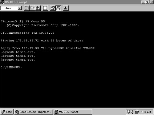
When an attempt is made to ping host C from host A or B, the first ping is successful and subsequent pings fail (Figure 6-18). Because at least one ICMP Echo Request packet reached C, and at least one Echo Reply packet was returned, the problem probably is not related to the hardware or data link.
The strange ping behavior leads to the hypothesis that after the first successful packet, subsequent packets—either the Echo Requests from B or the Echo Replies from C—are somehow being misdirected. Because this behavior is happening on the local data link, the Address Resolution Protocol (ARP) caches should be examined.
Example 6-30 and Figure 6-19 show the ARP caches for C and B, respectively. The suspicions about ARP are confirmed here. C’s cache contains the correct MAC address for B (00a0.2470.febd), but B’s cache has a MAC address of 0000.0c0a.2aa9 associated with C. A closer look at both caches shows that 0000.0c0a.2aa9 is the MAC address of San_Felipe’s locally attached interface. This information can be deduced because the same MAC address is mapped to IPv4 address 172.19.35.2 and to the IPv4 addresses reachable via that router.
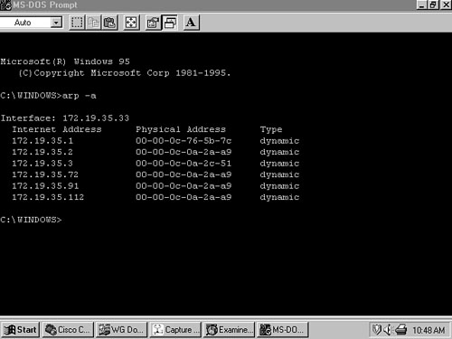
Figure 6-19. Host B’s ARP cache shows that C’s IPv4 address is mapped to the MAC address of San_Felipe’s interface 172.19.35.2.
Example 6-30. Host C’s ARP cache shows the correct MAC address associated with all addresses.
Linux 1.2.13 (Zuni.pueblo.com) (ttyp0)
Zuni login: root
Password:
Last login: Sat Nov 29 11:21:57 on tty1
Linux 1.2.13.
Zuni:~# arp -a
Address         HW type            HW address            Flags     Mask
172.19.35.112   10Mbps Ethernet    00:00:0C:0A:2A:A9     C         *
172.19.35.1     10Mbps Ethernet    00:00:0C:76:5B:7C     C         *
172.19.35.33    10Mbps Ethernet    00:A0:24:70:FE:BD     C         *
172.19.35.2     10Mbps Ethernet    00:00:0C:0A:2A:A9     C         *
172.19.35.3     10Mbps Ethernet    00:00:0C:0A:2C:51     C         *
172.19.35.9     10Mbps Ethernet    00:A0:24:A8:26:28     C         *
172.19.35.91    10Mbps Ethernet    00:00:0C:0A:2A:A9     C         *
Zuni:~#
The ping results begin to make sense. B broadcasts an ARP Request for 172.19.35.72. C sends an ARP Reply, and B sends its first ping correctly. In the meantime, San_Felipe has received the ARP Request and apparently believes that it has a route to 172.19.35.72. It responds with a proxy ARP (later than C because it has to perform a route lookup first), which causes B to overwrite C’s MAC address. Subsequent Echo Request packets are sent to San_Felipe, where they are routed off the local data link and lost. A protocol analyzer attached to the Ethernet proves the point (Figure 6-20).

Figure 6-20. A protocol analyzer, filtering for ARP packets, shows B’s ARP request to C and replies from both host C (00a0.24a8.a1a5) and router San_Felipe (0000.0c0a.2aa9).
If you know that the trouble is a routing problem, it remains only to find the cause. First, the subnet addresses for each data link should be determined (Figure 6-21). Next, C’s IPv4 address should be compared with all the subnets reachable via San_Felipe, in binary, to find any conflicts. Table 6-5 shows the addresses with the subnet bits of the last octet in bold.

Figure 6-21. When analyzing any addressing scheme, and especially a VLSM design, the subnets for every data link should be determined so that conflicts and overlaps may be discovered.
Table 6-5. C’s IPv4 addresses with subnet bits of the last octet highlighted.
Binary Representation | Dotted Decimal |
|---|---|
10101100000100110010001101001000 | 172.19.35.72/25 |
10101100000100110010001100000000 | 172.19.35.0/25 |
10101100000100110010001101000000 | 172.19.35.64/27 |
10101100000100110010001101100000 | 172.19.35.96/27 |
10101100000100110010001111001000 | 172.19.35.200/30 |
10101100000100110010001111001100 | 172.19.35.204/30 |
A comparison shows that the first three bits of 172.19.35.72/25 match subnet 172.19.35.64/27. San_Felipe has routes to both 172.19.35.0/25 and to 172.19.35.64/27 (Example 6-31). When it receives a packet destined for host C, it will be able to match one bit to subnet 172.19.35.0/25 but three bits to 172.19.35.64/27. As a result, the router will choose the more specific subnet and route the packet off the local data link and into oblivion.
Example 6-31. San_Felipe has routes to both 172.19.35.0/25 and to 172.19.35.64/27; the second route is a better match of host C’s address than is the first route.
San_Felipe#show ip route
Codes: C - connected, S - static, I - IGRP, R - RIP, M - mobile, B - BGP
       D - EIGRP, EX - EIGRP external, O - OSPF, IA - OSPF inter area
       E1 - OSPF external type 1, E2 - OSPF external type 2, E - EGP
       i - IS-IS, L1 - IS-IS level-1, L2 - IS-IS level-2, * - candidate default,
       U - per-user static route
Gateway of last resort is 172.19.35.1 to network 0.0.0.0
     172.19.0.0/16 is variably subnetted, 10 subnets, 3 masks
R      172.19.35.128/27 [120/1] via 172.19.35.3, 00:00:07, Ethernet0
R      172.19.35.160/27 [120/1] via 172.19.35.3, 00:00:08, Ethernet0
R      172.19.35.212/30 [120/1] via 172.19.35.3, 00:00:08, Ethernet0
R      172.19.35.208/30 [120/1] via 172.19.35.3, 00:00:08, Ethernet0
C      172.19.35.204/30 is directly connected, Serial0
C      172.19.35.200/30 is directly connected, Serial1
R      172.19.35.196/30 [120/1] via 172.19.35.1, 00:00:17, Ethernet0
C      172.19.35.0/25 is directly connected, Ethernet0
R      172.19.35.64/27 [120/1] via 172.19.35.206, 00:00:11, Serial0
R      172.19.35.96/27 [120/1] via 172.19.35.202, 00:00:23, Serial1
R* 0.0.0.0/0 [120/1] via 172.19.35.1, 00:00:18, Ethernet0
San_Felipe#
The solution to this trouble is to readdress either host C or subnet 172.19.35.64. This step sounds easy on paper. In real life, it may involve some difficult decisions, as it did for the client on whose network this case study is based.
Table 6-6 shows all the subnets of 172.19.35.0, based on a 27-bit mask. The intention was to combine the first four subnets into a single subnet with a 25-bit mask to accommodate up to 85 hosts on the “backbone” Ethernet. This decision is valid because the grouping will use all the subnets whose first bit is zero; no other address can cause a conflict. Next, 172.19.35.192/27 is subnetted with a 30-bit mask to be used on the serial links. Again, this design decision is valid. Subnets 172.19.35.128/27 and 172.19.35.160 are used as is. The error occurred when subnets 172.19.35.64/27 and 172.19.35.96/27 were selected to be used on two “remote” networks. These subnets had already been spoken for.
Table 6-6. A 27-bit subnet mask is applied to subnet 172.19.35.0.
Binary Representation | Dotted Decimal |
|---|---|
11111111111111111111111111111111 | 255.255.255.224 |
10101100000100110010001100000000 | 172.19.35.0/27 |
10101100000100110010001100100000 | 172.19.35.32/27 |
10101100000100110010001101000000 | 172.19.35.64/27 |
10101100000100110010001101100000 | 172.19.35.96/27 |
10101100000100110010001110000000 | 172.19.35.128/27 |
10101100000100110010001110100000 | 172.19.35.160/27 |
10101100000100110010001111000000 | 172.19.35.192/27 |
10101100000100110010001111100000 | 172.19.35.224/27 |
The difficult decision is in deciding whether to re-address the backbone, giving up some address space there, or to re-address the two remote subnets and give up address space on each of them. The second option was chosen, using a 28-bit mask to divide 172.19.35.224/27 into two subnets for the remote sites.
Although RIPv2 presents some decided improvements over RIPv1, it is still limited to a maximum of 15 hops and, therefore, to small networks. Chapter 7, “Enhanced Interior Gateway Routing Protocol (EIGRP),” Chapter 8, “OSPFv2,” and Chapter 10, “Integrated IS-IS,” examine three protocols that can be used in much larger networks and with which design strategies such as VLSM become very powerful tools for controlling them.
Command | Description |
|---|---|
accept-lifetime start-time {infinite | end-time| duration seconds} | Specifies the time period during which the authentication key on a key chain is received as valid |
auto-summary | Toggles the automatic summarization of routes on network boundaries |
debug ip rip [events] | Enables the display of messages on RIP transactions |
debug ipv6 rip | Enables the display of RIPng transactions |
ip classless | Enables the forwarding of packets on the route for which the router can find the best match without consideration of the class of the destination address |
ip rip authentication key-chain name-of-chain | Enables RIPv2 authentication on an interface and specifies the name of the key chain to be used |
ip rip authentication mode {text | md5} | Specifies whether an interface will use clear text or MD5 authentication |
ip rip receive version [1] [2] | Specifies the version or versions of RIP messages that an interface will accept |
ip rip send version [1] [2] | Specifies the version or versions of RIP messages that an interface will send |
ip split-horizon | Toggles the split horizon function on an interface |
ip subnet-zero | Allows the use of all-zeros subnets for interface addresses and routing updates |
ipv6 rip process-name enable | Enables the IPv6 RIPng process with the given name on the interface on which this command is issued |
ipv6 rip process-name metric-offset value | Modifies the metric associated with an inbound interface |
ipv6 rip process-name summary-address prefix | Summarizes longer prefix length prefixes into shorter prefixes |
ipv6 router rip process-name | Enables the IPv6, RIPng process on a router, and enters the configuration mode to change global RIPng parameters |
port port-num multicast multicast-value | Changes the UDP port number and/or multicast address for a RIPng process |
key number | Specifies a key on a key chain |
key chain name-of-chain | Specifies a group of keys |
key-string text | Specifies the authentication string, or password, used by a key |
network network-number | Specifies the network address of one or more directly connected interfaces on which IGRP, EIGRP, or RIP processes should be enabled |
passive-interface type number | Disables the transmission of routing updates on an interface |
router rip | Enables the RIP routing process on a router |
send-lifetime start-time {infinite | end-time| duration seconds} | Specifies the time period during which the authentication key on a key chain may be sent |
show ip route [address [mask]] [protocol [process-ID]] | Displays the current routing table as a whole or by entry |
show ipv6 rip | Displays the RIPng protocol information |
show ipv6 route rip | Displays routes installed into the IPv6 route table from the RIPng process |
version | Specifies the version of the RIP routing process |
In the example of Figure 6-12, router Taos was configured to send both Version 1 and Version 2 updates so that the routed process in the Linux host Pojoaque would understand the updates from Taos. Is there another way to configure Taos besides using the ip rip send version command? | |
A network has been assigned the address 192.168.100.0. Subnet this address to meet the following requirements: One subnet with 50 hosts Five subnets with 10 hosts One subnet with 25 hosts Four subnets with 5 hosts Ten serial links | |
Configure the four routers in Figure 6-22 to run RIP. RTC is running IOS 10.3 and for corporate policy reasons cannot be upgraded, therefore can only run RIPv1. | |
Configure RTB and RTD in Figure 6-22 to authenticate the RIP updates being exchanged over the serial link. | |
Configure RTB and RTD in Figure 6-22 to change to a new authentication key three days from the time the key in Configuration Exercise 4 went into effect. Have the new key stay in effect for 10 hours and then have the routers change to yet another key. | |
Configure RTA and RTB in Figure 6-22 to run RIPng. The following IPv6 prefixes are to be assigned to interfaces: RTA: 2001:DB8:0:1::/64 2001:DB8:0:2::/64 RTB: 2001:DB8:0:3::/64 2001:DB8:0:2::/64 |
Example 6-32 through Example 6-34 show the configurations for the three routers in Figure 6-23. Which subnets are in the routing tables of each router? From each router, which subnets are reachable and which subnets (if any) are unreachable? Example 6-32. The configuration of RTA in Figure 6-23. RTA#show running-config
Building configuration...
Current configuration:
!
version 11.2
no service udp-small-servers
no service tcp-small-servers
!
hostname RTA
!
!
!
interface Ethernet0
ip address 192.168.13.86 255.255.255.248
!
interface Serial0
no ip address
shutdown
!
interface Serial1
no ip address
shutdown
!
interface TokenRing0
ip address 192.168.13.34 255.255.255.224
ring-speed 16
!
router rip
version 2
network 192.168.13.0
!
no ip classless
!
!
line con 0
line aux 0
line vty 0 4
login
!
end
RTA#Example 6-33. The configuration of RTB in Figure 6-23. RTB#show running-config
Building configuration...
Current configuration:
!
version 11.2
no service udp-small-servers
no service tcp-small-servers
!
hostname RTB
!
!
!
interface Ethernet0
ip address 192.168.13.90 255.255.255.240
!
interface Serial0
no ip address
shutdown
!
interface Serial1
no ip address
shutdown
!
interface TokenRing0
ip address 192.168.13.35 255.255.255.224
ring-speed 16
!
router rip
version 2
network 192.168.13.0
!
no ip classless
!
!
line con 0
line aux 0
line vty 0 4
login
!
end
RTB#Example 6-34. The configuration of RTC in Figure 6-23. RTC#show running-config
Building configuration...
Current configuration:
!
version 11.1
service udp-small-servers
service tcp-small-servers
!
hostname RTC
!
!
!
interface Ethernet0
ip address 192.168.13.75 255.255.255.224
!
interface Serial0
no ip address
shutdown
!
interface Serial1
no ip address
shutdown
!
interface TokenRing0
ip address 192.168.13.33 255.255.255.224
ring-speed 16
!
router rip
network 192.168.13.0
!
no ip classless
!
line con 0
line 1 8
line aux 0
line vty 0 4
login
!
end
RTC# | |
The configurations of RTA and RTB in Figure 6-23 are changed as follows:[14] interface Ethernet0 ip address 192.168.13.35 255.255.255.224 ip rip receive version 1 2 Will any subnets be added to any routing tables as a result of this change? Explain why or why not. |
[1] Supplemental to this RFC are RFC 1721, “RIP Version 2 Protocol Analysis,” and RFC 1722, “RIP Version 2 Protocol Applicability Statement.”
[2] This figure is an adaptation of an example presented by Gary Malkin in RFC 1722.
[3] Redistribution refers to the practice of advertising routes learned from one protocol to another protocol; it is discussed in detail in Chapter 11, “Route Redistribution.”
[4] This method would work only if no other interface on the router on which RIP should run is attached to the same major network.
[5] This statement assumes that the all-zeros and all-ones subnets—the only subnets available with a single bit of subnetting—can be routed.
[6] The reader is strongly encouraged to work through this entire example in binary.
[7] Subinterfaces are logical interfaces configured on a physical interface. Many subinterfaces can be configured on a single physical interface, and each subinterface can have its own IP address; routing protocols treat them the same as physical interfaces. Subinterfaces are particularly useful with Frame Relay, ATM, and VLANs. Readers who are not already familiar with these useful tools are referred to the Cisco Configuration Guide.
[8] MD5 is described in RFC 1321. A good discussion of MD5 can also be found in the following book: Charlie Kaufman, Radia Perlman, and Mike Spencer, Network Security: Private Communication in a Public World. Prentice Hall, 1995, pp. 120–122.
[9] Intentionally misconfigured for this example actually, with the routed -s option.
[10] Now that the concept should be firmly in place, from here on the single term subnet will be used for a subnet, a sub-subnet, a sub-sub-subnet, or whatever.
[11] The technique used here to combine several addresses into one address serves as an introduction to address aggregation, covered in Chapter 7.
[12] NTP is outside the scope of this book. Refer to the Cisco Configuration Guide for more information.
[13] MPLS VPNs allow multiple RIP processes to run on a single provider edge router. A single RIP process is configured for a given VPN. MPLS and VPNs are outside the scope of this book.
[14] The configuration shown is for RTB. RTA is identical, except for the IP address, which is 192.168.13.34.