
Fault Detection via Redundant Execution
6.1 Overview
Fault detection via redundant execution is a common form of fault detection that has been used for decades. Unlike error coding techniques—described in the previous chapter—that detect faults using redundant information in storage bits or logic units, the techniques described in this chapter detect faults by comparing outputs from redundant streams of instructions. Typically, fault detection via redundant execution can provide greater fault coverage across a processor chip compared to error coding techniques on individual hardware structures. This is because the same redundant execution technique can cover multiple hardware structures, unlike in many error coding implementations where each structure must be protected individually. Further, redundant execution can more easily protect logic and computation blocks that change the data the blocks operate on. In contrast, error coding techniques are typically used for storage and communication that leave the data unchanged over periods of time. Redundant execution techniques can, however, add significant hardware overhead over error coding schemes.
This chapter focuses on two redundant execution schemes commonly used in the industry: Lockstepping and Redundant Multithreading (RMT). In Lockstepping, both redundant copies have exactly the same state in every cycle. Consequently, a fault in either copy may cause the redundant copies to produce different outputs in the same cycle. A fault is detected on such an output mismatch. In contrast, in RMT, only outputs of committed instructions are compared. The internal state of the individual redundant threads in an RMT implementation can be very different.
This chapter discusses the different trade-offs offered by Lockstepping and RMT. To illustrate the trade-offs, this chapter first discusses the concept of the sphere of replication. The sphere of replication determines the logical boundary within which all states are logically or physically replicated. The sphere of replication is critical to understand the outputs in a Lockstepped or an RMT implementation that need comparison.
Then, this chapter describes three Lockstepped implementations—the Stratus ftServer, the Hewlett-Packard NonStop Architecture, and the IBM Z-series processors. These three examples illustrate how varying the size of the sphere of replication can change the trade-offs associated with implementing Lockstepping.
Finally, five RMT implementations are discussed—the Marathon Endurance Server, the Hewlett-Packard NonStop Advanced Architecture (NSAA), simultaneous and redundantly threaded (SRT) processor, the chip-level redundantly threaded (CRT) processor, and dynamic implementation verification architecture (DIVA). Because RMT implementations do not impose the constraint of cycle-by-cycle synchronization, one can implement the redundant threads of RMT in a variety of ways: in a hardware thread, in a processor core, or in a special checker core. These five implementations differ not only in the size of the sphere of replication but also in how the redundant threads are implemented. The first two have been implemented in commercial systems, whereas the last three designs are only paper proposals but have been studied extensively by researchers.
6.2 Sphere of Replication
The concept of the sphere of replication [10] makes it easier to understand the mechanics of fault detection schemes based on redundant execution, such as Lockstepping or RMT. In a fault detection scheme with redundant execution, the same program executes as identical and committed instruction streams. For a dual-modular redundancy (DMR) system, there are two identical streams. For a triple modular redundancy (TMR) system, there are three identical streams of execution. Specific outputs are compared from each stream. A fault is flagged when there is a mismatch in the compared outputs.
6.2.1 Components of the Sphere of Replication
The sphere of replication identifies the logical domain protected by the fault detection scheme. That is, any fault that occurs within the sphere of replication and propagates to its boundary will be detected by the fault detection scheme corresponding to the sphere of replication. Figure 6.1 shows an example sphere of replication that includes redundant copies of a microprocessor but excludes memory, disks, and other I/O subsystems. There are three questions related to the sphere of replication:

![]() For which components will the redundant execution mechanism detect faults? Components outside the sphere of replication are not covered by redundant execution and may need to use alternative techniques, such as parity, ECC, or replication, for fault coverage.
For which components will the redundant execution mechanism detect faults? Components outside the sphere of replication are not covered by redundant execution and may need to use alternative techniques, such as parity, ECC, or replication, for fault coverage.
![]() Which outputs must be compared? Failure to compare critical values compromises fault coverage. However, needless comparisons increase overhead and complexity without improving coverage.
Which outputs must be compared? Failure to compare critical values compromises fault coverage. However, needless comparisons increase overhead and complexity without improving coverage.
![]() Which inputs must be replicated? Failure to correctly replicate inputs can result in the redundant threads following divergent execution paths.
Which inputs must be replicated? Failure to correctly replicate inputs can result in the redundant threads following divergent execution paths.
6.2.2 The Size of Sphere of Replication
The extent of the sphere of replication affects a number of system parameters. A larger sphere typically replicates more state (e.g., memory). However, moving state into the sphere indicates that updates to that state occur independently in each execution copy. Thus, a larger sphere tends to decrease the bandwidth required for output comparison and input replication, potentially simplifying the comparator and replicator circuits.
The size of the sphere of replication also depends on how much control vendors have over the components they use in their machines. For example, vendors, such as Tandem or Stratus, do not have much control over the microprocessor itself and hence their spheres of replication include two or three microprocessor chips. In contrast, IBM designs its own fault-tolerant microprocessor and hence it can afford to create a sphere of replication that is limited to a single microprocessor, but with redundant pipelines.
In practice, the size of the sphere of replication can vary widely. The sphere of replication in Stratus’ ftServer [19] includes redundant copies of both the microprocessor and the main memory (Figure 6.2). In contrast, the sphere of replication of the Hewlett-Packard Himalaya system [23] includes only redundant copies of the microprocessor but not the main memory or I/O system. The sphere of replication in the IBM G5 processor [13], on the other hand, comprises only part of the processor pipeline—fetch, decode, and execution units. Even the architectural register file in the G5 is outside the sphere of replication.

FIGURE 6.2 Sphere of replication (shaded region) that includes memory but excludes disk and other I/O.
Compute the DUE FIT rate of the following microprocessor. The microprocessor has two parts: a core and an uncore. The core has 60 SDC FIT and 60 DUE FIT. The uncore has 40 SDC FIT and 40 DUE FIT. Designers decided to add redundant execution to the microprocessor with the sphere of replication covering the entire core. Assume that the false DUE FIT arising from the redundant execution is 10 DUE FIT.
SOLUTION Redundant execution eliminates the SDC FIT for the core since the sphere of replication includes the entire core. The DUEFIT = 10 (falseDUE) + 60 (from core) + 40 (from uncore) = 110 FIT. So, the total SDC FIT reduces from 100 FIT to 40 FIT, but the DUE FIT increases from 100 FIT to 110 FIT.
6.2.3 Output Comparison and Input Replication
Any outputs leaving the sphere of replication must be compared to check for mismatch and corresponding faults. Faults that do not propagate to the output comparator corresponding to the sphere get masked and hence do not require detection or comparison. The output comparator has also been referred to in the literature as the checker.
Any inputs into the sphere of replication must be appropriately replicated and delivered to the correct points within the sphere. If the inputs are not replicated correctly, then the redundant copies may still execute correctly but may follow different (but still correct) paths. For example, if the redundant copies read a processor cycle counter but obtain different values for the same cycle counter, then the redundant copies may diverge. Although the individual copies will execute correctly, the output comparison may indicate a mismatch even in the absence of a fault because of divergent execution. Hence, it is critical to ensure that both copies execute the same correct path in the absence of any fault. This can be ensured if the inputs are replicated appropriately.
Broadly, there are two styles of output comparison and input replication. First one is cycle synchronized. That is, each redundant copy within the sphere has exactly the same state in every clock cycle as its redundant copy. The Stratus ftServer, for example, is cycle synchronized. This is typically referred to as Lockstepping since the redundant copies within the sphere are exactly in sync in every cycle. The output comparator can compare any set of hardware signals coming from the redundant copies in the sphere. In the absence of any fault, these signals should match exactly in each cycle. It should be noted that the output comparator does not need any semantic information about the signals. As long as the signals match, the comparator can certify that the redundant copies did not encounter a single-bit fault.
The second style is one that compares specific events or instructions, instead of hardware signals, from two executing streams of instructions. For example, the Tandem NSAA [2] has the same sphere of replication as the Stratus ftServer but is not cycle synchronized. Instead, the Tandem NSAA compares I/O events coming from two separate microprocessors. To avoid cycle-by-cycle synchronization, the NSAA takes special care in replicating the inputs, such as interrupts and DMA activities. This is normally referred to as Loose Lockstepping or RMT. The next two sections describe several styles of Lockstepped and RMT systems.
6.3 Fault Detection via Cycle-by-Cycle Lockstepping
Lockstepping is a well-known fault detection technique and has been used since the 1980s by mainframes and highly reliable computers. Since the 1960s and 1970s, companies, such as Stratus, Tandem, and IBM, have built fault-tolerant computers that failed over to a standby backup machine when the primary failed. However, the fault coverage in these machines was not as evolved as in today’s fault-tolerant machines. In the 1980s, more and more business applications, such as online transaction processing, started to run continuously (24 hours a day, 7 days a week). This required the processors themselves to be online 24 × 7 with very little downtime and high fault coverage and detection capabilities. To meet this market demand, in the 1980s, Stratus and Tandem introduced Lockstepped processors in their systems (besides other enhancements to the memory and I/O subsystem), but IBM relied on extreme levels of error checking throughout its processor and system design. In the 1990s, however, IBM switched to a Lockstepped processor pipeline architecture.
In the cycle-by-cycle Lockstepping, redundant copies of a program are executed through cycle-synchronized redundant hardware. An output comparator compares a set of hardware signals from each redundant copy. On a mismatch, the comparator flags an error. Thus, Lockstepping reduces the SDC rate of a system. Lockstepping by itself, however, does not imply the presence or absence of any accompanying recovery mechanism, such as checkpointing, or the use of TMR that allows systems to make progress even after a fault is detected.
Lockstepping necessitates a cycle-by-cycle synchronization of the redundant hardware. That is, in each cycle, both hardware copies have exactly the same state, execute the same stream of instructions, and produce the same stream of events in exactly the same cycles. In the absence of a cycle-level synchronization, the two redundant copies can diverge rapidly. This effect is even more prominent in dynamically scheduled processors1, which can speculatively execute instructions that may not be on the correct path. Cycle synchronization is difficult to implement in a logically shared hardware (e.g., within a multithreaded processor core) and hence typically Lockstepping uses physically redundant and identical copies of the hardware. Cycle-by-cycle synchronization also makes input replication easier since the inputs will be correct as long as the replicated inputs are delivered in the same cycle to the redundant hardware.
Lockstepping poses two critical constraints on the system design. First, the redundant copies must be fully deterministic. That is, they must produce the same set of output signals, given the same set of input signals.
Second, the hardware must support deterministic reset. On a reset, a microprocessor’s or a chipset’s state is set to a specific state. This state must be identical for both redundant copies of the hardware, even for the state that does not affect correct execution of the pipeline. For example, a branch predictor’s initial state does not affect the correct execution in the absence of Lockstepping. However, if the redundant microprocessors have different initial state in their branch predictors, then they are highly likely to diverge and cause a Lockstepping mismatch. A branch misprediction could trigger an incorrect path load in one copy, whereas a correct prediction may not trigger the same in the redundant copy causing a Lockstep failure.
The rest of the section discusses the advantages and disadvantages of Lockstepping and describes three commercial implementations of Lockstepped systems. These commercial systems differ in the sizes of the sphere of replication chosen for the Lockstepped implementation.
6.3.1 Advantages of Lockstepping
Lockstepping provides a great degree of fault coverage. It can detect almost all transient faults in the physically redundant copies within the sphere of replication. It cannot detect faults that are masked within the sphere of replication, which are faults one usually does not care about. Lockstepping can also detect most permanent faults in either copy. The only transient and permanent faults Lockstepping cannot detect are the ones that affect the redundant copies in exactly the same way. But the likelihood of two faults affecting the two redundant copies in exactly the same way is extremely low, unless it is caused by a design fault, which could potentially affect both redundant copies in the same way.
Lockstepping can be implemented purely as a hardware layer underneath applications and OS. As long as all inputs—specifically hardware signals feeding the sphere of replication—are correctly replicated to the two redundant copies, all software, including applications and OS, on both the redundant copies of the hardware will execute the same stream of instructions. Then, any mismatch in the stream of instructions due to a fault will be caught by the output comparator. This makes it an attractive solution for system vendors, such as Stratus, who have little control over the microprocessor they may be using or the OS they may have to run.
6.3.2 Disadvantages of Lockstepping
Lockstepping does, however, come with some significant disadvantages. The cost of a Lockstepped system is higher than that of a normal machine since it uses redundant copies of the hardware. At the extreme, the performance-per-unit price of such a system could be nearly half that of a commodity non-fault-tolerant system. In other words, the same dollars could purchase approximately twice as many commodity systems as fault-tolerant systems. Hence, the cost of fault tolerance must be weighed against the customer’s penalty incurred from the downtime of the machines.
The validation time for a Lockstepped system can also be higher than that for a normal machine. This is because Lockstepping requires each redundant copy to execute deterministically to produce the same output when fed with the same input. Given up to a billion transistors on today’s chips, nondeterminism can arise easily in a microprocessor or a chipset implementation. For example, a floating bit that assumes random values due to circuit marginality may not cause incorrect execution but may easily cause a Lockstep failure. Similarly, clock domain crossing may induce clock skews differently in the redundant copies of the hardware, which may again cause Lockstep failures. The implementation-related nondeterminism must be weeded out for Lockstepping to work correctly.
Validating that a microprocessor will execute deterministically over months or years is a nontrivial job. Typically, testers used in the validation of microprocessors and chipsets can only run for millions of cycles. In a tester, the chip under test is fed with input vectors and compared against a predefined set of output vectors. This process can guarantee fully deterministic operation only for millions of cycles but not for months or years. Hence, a whole range of functional tests are run on the microprocessor to guarantee that the microprocessor will operate correctly over months of operation. These functional tests, however, do not guarantee determinism. Hence, validating that a microprocessor will operate deterministically over months or years is a challenging proposition.
Also, Lockstepping often needs to be accompanied by a recovery mechanism because of its potential to increase the false DUE rate. Recall that the false DUE events arise from benign faults that are detected by the fault detection mechanism (see Silent Data Corruption and Detected Unrecoverable Error, p. 32, Chapter 1). For example, faults in branch predictors may cause one of the Lockstep processors to execute wrong-path instructions that are different from the ones executed by its Lockstep pair (Figure 6.3). This is likely to cause a Lockstep failure and hence is a false DUE event. Similarly, structures that do not have in-line recovery may trigger false DUE events. For example, a parity-protected write-through cache can recover from a strike on the data portion of the cache by refetching the block from a lower level memory. But this refetch operation may cause a timing mismatch with the other Lockstep processor, which may not initiate a refetch in the absence of a fault (Figure 6.4). This would again cause an unnecessary Lockstep failure. Any out-of-band ECC flow would cause a similar problem. One option would be to turn the parity or ECC check off, which may or may not be possible depending on whether the processor had the option to turn it off. Alternatively, this parity or ECC check event could be signalled to the Lockstep output comparator, which could do a fast reset and restart of the whole system. The case studies on Lockstepping in Chapter 3 (see Case Study: False DUE from Lockstepped Checkers, p. 87) show that false DUE can contribute significantly to the total DUE rate of the Lockstepped system.

FIGURE 6.3 Lockstep violation due to a strike on a branch predictor of processor A. The notation Rn = [Rm] denotes that register Rn is loaded from the memory location Rm. Each row shows the instructions seen by the execution unit of each processor. The processors A and B are in Lockstep in cycle n. In cycle n + 1, processor A goes down the wrong path due to a strike on its branch predictor. Processor B, however, still remains on the correct path. Processor A returns to the correct path in cycle n + 3, but the two processors are no longer cycle synchronized. Lockstep output comparators that check instruction signals at the memory likely detect this violation immediately. Lockstep output comparators that check signals at the memory or I/O boundary will eventually detect such a timing mismatch.

FIGURE 6.4 Lockstep violation due to a parity check followed by refetch of cache line in processor A. Each row shows the instruction committed in the specific cycle in each processor. In cycle n + 1, processor A’s cache gets a parity error and must refetch the cache line. Processor B does not get a parity error and proceeds without any hiccup. Processor A eventually commits the offending instruction in cycle n + 4, but by that time, both processors are already out of Lockstep.
False DUE events can also arise in Lockstep processors from faults in un-ACE instructions that may not cause a timing mismatch. For example, an alpha particle or a neutron strike on the result of a dynamically dead instruction is un-ACE since there is no further consumer of the result value. But a fault detection resulting from a mismatch in the result of the corresponding dynamically dead instructions in a Lockstep processor pair will be a false DUE event.
Chapter 7 discusses recovery mechanisms to reduce both true and false DUE rates arising in a Lockstep system. The next three subsections describe three different commercial Lockstep systems, each with a different sphere of replication.
Assume that a processor write-back cache has a DUE FIT of 500 when protected with parity and DUE FIT of 0 when protected with SECDED ECC. When the ECC is invoked, it requires an extra cycle to correct the error. Also, assume that the processor branch predictor has an intrinsic SDC rate of 100 FIT. The branch predictor’s AVF is zero for a single processor, so the total SDC rate of the branch predictor is zero in non-Lockstep mode. Two such processors are now Lockstepped. What is the false DUE rate for this Lockstepped pair? Assume false DUE arises only from the cache and branch predictor.
SOLUTION From the cache, the false DUE rate for Lockstepping is 500 × 2 = 1000 FIT (the factor 2 arises because of two processors in a pair). From the branch predictor, the SDC FIT rate is 100 × 2 × 0.1 = 20 FIT, if one assumes a Lockstep AVF of 10%. The total false DUE FIT arising from Lockstepping is 1020 FIT.
6.3.3 Lockstepping in the Stratus ftServer
The Stratus ftServer (Figure 6.5) provides a very high level of fault tolerance using redundant Lockstepped processors and redundant I/O components [19]. Stratus Technologies has a long history of building custom fault-tolerant computers since the early 1980s [12]. Like Stratus’ previous machines, the ftServer is targeted for use in mission-critical applications (see SDC and DUE Budgets, p. 34, Chapter 1), which can tolerate extremely low levels of SDC and DUE rates. Unlike Stratus’ prior fault-tolerant computers, however, the ftServer uses commodity off-the-shelf components, such as Intel x86 processors and Windows Server 2003 and Linux OS. The processor nodes themselves can either be multicore or symmetric multiprocessors (SMP).

FIGURE 6.5 Stratus ftServer. Reprinted with permission from Somers [19]. Copyright © 2002 Stratus Technologies.
The ftServer comes in two configurations: DMR or TMR. In the DMR configuration, the sphere of replication comprises dual-redundant Lockstepped processors, dual copies of main memory, and dual copies of the chipset. The “fault detection and isolation” component in Figure 6.5 consists of the output comparator and the input replicator. Output comparison is done at the I/O boundary before traffic goes into the PCI2 bus. Input replication is done at the I/O boundary as well. The output comparator, input replicator, and the I/O components themselves (e.g., PCI bus, disks) are mirrored for added fault tolerance. The Ethernet network adapter is not mirrored but has three backup adapters. During transmission, all four adapters are used, but packets can be received only on a single adapter. The ftServer has fault detection mechanisms on other mechanical components, such as the power supply and the fans.
In the DMR system, if one output is in error, then the node that generated that output is shut down, but the other node continues execution. In the event that a miscompare occurs between two outputs, the DMR comparator waits for a corresponding error signal to propagate from one of the two Lockstepped nodes. The error signal could arise from a number of sources, including internal parity errors, power errors, and thermal errors in one of the Lockstepped pairs. Then, the comparator knows not only that there is an error but also which of the two systems is faulty. Based on this information, it removes the offending node (processor, memory, and chipset) from service and initiates a service call with Stratus. In the absence of the internal error signal, the ftServer removes a node from service based on a software algorithm that takes various heuristics, such as age of the components, into account. In all cases, the system continues to operate without interruption.
In the TMR mode, however, the ftServer does not need to make use of the error signal. This is because on a single fault, two of the three systems must be correct. Once it identifies the faulty system, it removes the offending node from service and continues in the reduced DMR mode. It also initiates a service call to Stratus to repair the degraded system.
Interestingly, the ftServer can run a commodity OS without any significant change because the underlying hardware is completely Lockstepped. Each individual OS image in the ftServer has no knowledge that there are other redundant images of the same OS working in Lockstep. In contrast, the Hewlett-Packard NSAA (see RMT in the Hewlett-Packard NonStop® Advanced Architecture, p. 225) needs to modify its OS because it does not implement strict cycle-by-cycle Lockstepping.
The use of the Windows OS does, however, require the ftServer to take some additional steps3. Errant device drivers are acknowledged as the root cause of many of the Windows crashes. Microsoft itself has estimated that device drivers are responsible for 30% of Windows NT® reboots. Hence, the ftServer takes additional steps to ensure that device drivers do not cause Lockstep failures or crashes. For example, the ftServer only installs device drivers that pass the Microsoft Windows 2003 WHQL (Windows Hardware Quality Labs) tests. Further, Stratus has hardened the device drivers through extensive testing and additional error checks either by licensing the device driver from the vendor or by working with the vendor. The ftServer also isolates the PCI adapters from the rest of the system when it detects device driver problems.
6.4 Lockstepping in the Hewlett-Packard NonStop Himalaya Architecture
Like Stratus Technologies, Tandem Computer Systems has been building fault-tolerant computer systems for mission-critical applications since the late 1970s [12]. In the late 1980s, Tandem introduced custom-built Lockstepped processors into its fault-tolerant computers to respond to market demands for highly available fault-tolerant computers. Tandem started using commodity MIPS®-based RISC processors in its Lockstepped machines from the early 1990s. However, unlike Stratus’ recent move to use a commodity OS, Tandem continues to use its own in-house fault-tolerant OS called the NonStop kernel. In 2001, Hewlett-Packard acquired Compaq Computer Corporation, which in turn had acquired Tandem Computer Systems in 1997. Tandem continues to design and sell fault-tolerant computers under the Hewlett-Packard NonStop brand name.
Figure 6.6 shows a block diagram of the Hewlett-Packard NonStop Himalaya system [23]. It uses Lockstepped off-the-shelf MIPS microprocessors. Like the Stratus ftServer, it also is targeted to tolerate extremely low levels of SDC and DUE. The sphere of replication comprises the microprocessor (and its associated off-chip caches) and the interface ASICs responsible for output comparison and input replication. Unlike the Stratus ftServer system, main memory in Hewlett-Packard’s NonStop Architecture is outside the sphere of replication. Consequently, the NonStop Architecture does not have to replicate the entire main memory. Instead, it protects main memory using ECC.

FIGURE 6.6 Hewlett-Packard NonStop Architecture with Lockstepped microprocessors and ServerNet as the interconnect fabric.
The I/O subsystem is also outside the sphere of replication. The I/O system is connected to the processors using an in-house network called ServerNet, which forms the backbone of the current NonStop Architecture. ServerNet is a fast, scalable, reliable, and point-to-point system area network that can connect a large number of processors and I/O peripherals. ServerNet provides independent redundant paths for all traffic via independent X and Y subnetworks.
To provide recovery from faults, the NonStop Himalaya servers use process pairs implemented by the NonStop kernel. One of the processes in a process pair is designed as the primary and the other one as the backup. The primary process runs on a pair of Lockstepped processors and regularly sends checkpointing information to the backup process, which runs on a pair of Lockstepped processors as well. When the primary process experiences a Lockstep error, the backup process takes over and continues to run. Hewlett-Packard Corporation also offers a TMR solution in its NonStop Integrity line of servers, which do not require the use of process pairs.
Recently, Hewlett-Packard moved away from Lockstepped systems for Redundantly Multithreaded systems. Hewlett-Packard calls this its NSAA. This implementation is discussed later in this chapter (see RMT in the Hewlett-Packard NonStop® Advanced Architecture, p. 225).
6.5 Lockstepping in the IBM Z-series Processors
IBM has been designing fault-tolerant machines since the late 1960s but waited to introduce its Lockstepped processor architecture as late as the mid-1990s. In the early 1990s, IBM moved the processors used in its high-end fault-tolerant machines from emitter-coupled logic (ECL) to CMOS technology. Successive generations of these CMOS processors were codenamed G1-G6, and z900 and more recently z990 and z9 EC. In the ECL processors and in G1 and G2 CMOS processors, IBM used extensive per-structure error checking logic in its pipeline. IBM estimates the total area overhead from such error checking logic to be between 20% and 30% of single nonchecked pipeline [13].
With the move to CMOS technology, IBM designers found it increasingly difficult to increase the processor frequency with extra levels of error checking logic in the critical path of the pipeline. Hence, with the introduction of the G3 microprocessor, IBM moved to a Lockstepped pipeline implementation in which the error checking logic was removed from the critical path. Instead, the instruction fetch and execution units were replicated and checked for errors at the end of the pipeline. Spainhower and Gregg [20] estimate the area overhead from this Lockstepped implementation to be 35%. IBM used this dual fetch and execution unit through its z990 architecture. In the more recent z6 architecture, however, IBM has reverted to a non-Lockstepped implementation that has as many as 20 000 error checkers sprinkled across the microprocessor [22].
Figure 6.7 shows the IBM G5’s Lockstepped processor architecture. The G5 consists of four units: the buffer control element (BCE), the I unit, the E unit, and the R unit. The BCE consists of the L1 cache and TLBs. The I unit is responsible for the instruction fetch, decode, address generation, and issue queue that issues instructions to the E unit. The E unit consists of the execution units and local copies of the register files. The R unit is responsible for fault detection and recovery. It holds checkpointed copy of the entire microarchitectural state of the processor (including the architecture register file), timing facility, and other miscellaneous state information.4

FIGURE 6.7 IBM G5 microprocessor. Reprinted with permission from Slegel et al. [13]. Copyright © 1999 IEEE.
The sphere of replication in the G5 consists of replicated I and E units. Figure 6.7 shows signals from replicated units (dashed arrows). Any updates to the architecture register file (in the R unit) or caches (in the BCE) must be first checked for faults (output comparison). Similarly, any inputs into the I or E unit must be replicated appropriately (input replication). Unlike Stratus’s ftServer or Tandem’s NonStop Himalaya Architecture, the sphere of replication in the IBM machine is much smaller. The G5’s sphere of replication excludes not only main memory and I/O components but also the caches and architected register file. Consequently, all arrays in the BCE and R unit must be protected to allow complete fault coverage. For example, the L1 cache is write-through, so it uses parity codes to recover from faults. The store buffer and the architecture register file are protected with ECC. Although the architecture register file lives outside the sphere of replication in the R unit, the G5 maintains shadow copies of the register file in the E units to speed up execution.
When the R unit or L1 cache detects a fault, the pipeline commits pending updates from retired instructions and discards any state corresponding to nonretired instructions. Then, it resets all internal state in the I and E units. The R unit is read out in sequence with ECC logic, correcting any errors in the registers. The shadow copies of the register file are also updated in parallel. The R unit registers are read a second time to ensure that there are no hard correctable errors. Finally, the E unit restarts instruction fetching and execution. If the Lockstep violation was caused by a transient fault, such as an alpha particle or a neutron strike, then the pipeline can recover using this mechanism. However, if the second read of the R unit indicates an error or the E unit cannot successfully retire an instruction, then the machine has probably encountered a hard error. The pipeline is halted with a different sequence of diagnosis and recovery invoked to deal with the latter case.
Forwarding replicated signals from the I and E units to R unit and L1 cache can cause extra delays along the pipeline. To avoid slowing down the pipeline, the z990 processor [14]—a later version of the G5 processor—skews the signals from the replicated units by one cycle. Signals from the primary I and E units arrive at the output comparators a cycle earlier than the replicated ones. This allows the primary units to be packed close to the nonreplicated units, such as the caches, and the replicated units to be placed further apart.
6.6 Fault Detection via RMT
RMT is a fault detection mechanism, which like cycle-by-cycle Lockstepping, runs redundant copies of the same program and compares outputs from the redundant copies to detect faults. Recall that in Lockstepping outputs are compared and inputs are replicated at a hardware clock or at a cycle boundary. In contrast, in RMT, output comparison and input replication happen at a committed instruction boundary. A committed instruction is one whose result the processor commits and does not discard, for example, due to a misspeculation internal to the processor. Like “multithreading,” RMT itself is a concept, not an implementation. RMT can be implemented on most, if not all, implementations of multithreading, such as simultaneous multithreading (SMT) or multicore processors.
Comparing outputs and replicating inputs at a committed instruction boundary enables RMT to relax many of the constraints imposed by cycle-by-cycle Lockstepping. RMT does not require the hardware running the redundant copies of a program to have exactly the same microarchitectural state in every cycle. Examples of structures that hold microarchitectural state are the branch predictor, instruction queue, caches, etc. Instead, RMT only requires that the redundant copies have the same architectural state (e.g., architectural register file, memory) at a committed instruction boundary. Unlike microarchitectural state, architectural state of a machine corresponding to program is visible to a user or a programmer.
Relaxing the constraint of cycle synchronization allows great flexibility in RMT implementations. As is shown later, RMT can be implemented across whole systems, within a single system, across two similar and different processor cores, and within a single-processor core. Chapter 8 discusses how RMT can be implemented purely in software as well. For pure hardware RMT implementations, relaxing the constraint of cycle synchronization makes functional validation of the RMT implementation much easier since much of the validation can be done in a presilicon design phase.
Relaxing the constraint of cycle synchronization, however, makes input replication more complicated in RMT than in Lockstepping. This section shows how five different RMT implementations deal with input replication in different ways. How the sphere of replication differs in each of these implementations is also explained.
6.7 RMT in the Marathon Endurance Server
Marathon Technologies Corporation was perhaps the first to implement an RMT-based fault-tolerant machine using redundant processors in a commercially available server called EnduranceTM 4000. The company was founded in 1993 on the premise of this technology. The key to Endurance’s success is its use of commodity OSs, such as Windows OS, and commodity microprocessors, such as the Intel Pentium processors. Another key feature of the Endurance machine is its ability to tolerate disasters (e.g., terrorist attack) by separating the redundant processors up to 1.5 km apart. Because of such loose coupling between the redundant processors, Marathon had to adopt the RMT model instead of the cycle-by-cycle Lockstepping.
Recently, Marathon Technologies has moved away from the Endurance servers, which required some custom hardware. Today, Marathon’s EverRun servers provide fault tolerance using a pure software implementation based on virtualization technology (see Chapter 8).
Figure 6.8 shows a block diagram of the Endurance machine [3]. It consists of two compute elements (CEs) and two I/O processor boxes. All four processors—one in each CE and one in each I/O—are commodity Intel Pentium microprocessors that run the Windows NT OS. The CEs execute the redundant threads as an RMT pair. The sphere of replication consists of the two CEs, which include the microprocessor, the main memory, and a proprietary Marathon InterConnect (MIC) card. The MIC connects the two CEs and the two I/O processors. The MIC links can be up to 1.5 km in length, thereby allowing a CE and an I/O processor slice to be located physically apart from its pair.
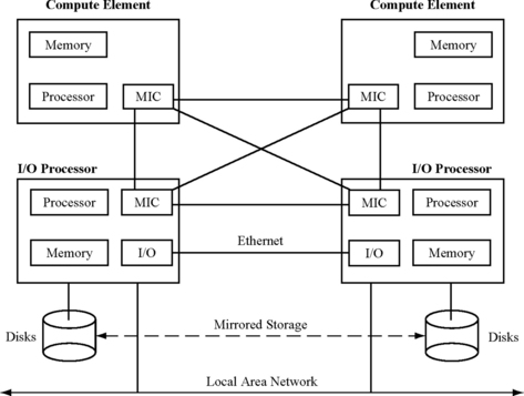
FIGURE 6.8 Block diagram of the Marathon Technology Endurance™ Series Machine. MIC = Marathon’s Proprietary Interconnect ASIC.
The I/O processors do the output replication. The CEs forward their I/O requests to both I/O processors, each of which compares both requests for any mismatch. The storage system is mirrored across both I/O processors. The network adapter is also replicated. Network packets can be received in either I/O processor, but packets can only be sent out through one of the two I/O processors. If one of the sending adapters fails, the other one takes over. In an implementation with reduced coverage, it is also possible to have only one I/O processor.
The input replication is a little more involved. To ensure that both the redundant threads execute the same committed instruction stream, the inputs—including asynchronous interrupts and I/O responses—must be replicated to both threads at exactly the same instruction boundary. When the two redundant processors run independently of each other, this condition is hard to guarantee. The Hewlett-Packard NSAA, described in the next section, is able to do this with OS support. But the Marathon Endurance machine runs a commodity OS and hence does not have this advantage.
Instead, the Endurance machine divides up the instruction stream into successive quanta. At the beginning of each quantum, the performance counter is set to trigger a callback after a specific number of instructions have been committed. All other interrupts are disabled. When a quantum expires, each redundant processor enters into a special mode in which each tries to ensure that it has reached the same instruction in the execution stream with the same state. This special mode consists of a complex combination of instruction execution, single stepping, and breakpointing. The synchronization requests during this interval are sent to the I/O processors, which try to determine if both processors have reached the same point of execution. At the end of this synchronization phase, both processors reach the same instruction boundary. At this point, all inputs are replicated via the MIC to the redundant processors. This includes also the logical time delivered to both the processors by the I/O processor, which acts as a time server.
The Endurance machine prevents any SDC since I/O writes are checked before written to disk. On an RMT mismatch, the I/O processors try to determine the CE that failed. If the diagnosis is successful, then the failed CE will be restarted or replaced and restarted as the case may be. When the failed CE comes back up, it automatically synchronizes with the running CE, which continues running in a nonredundant mode throughout the recovery period.
If the I/O processors cannot, however, determine the CE that had the data corruption, then there are two options available to the system administrator for configuring the system response to indeterminate CE data corruption. If the system was configured for data availability, the CE that is removed is the slave CE (recipient of the last synchronization). If the system was configured for data integrity, then the entire system is rebooted and restarted.
I/O processor errors are handled similarly. For data availability, the I/O processor with the poorest selection of devices will be removed (I/O boot drive, CE boot drive, CE Data drives, Ethernet ports, memory, etc). If the I/O processors are indistinguishable in capabilities, then the I/O processor that did not boot the master CE (source of the last synchronization) is removed. For data integrity, the entire system must be rebooted.
6.8 RMT in the Hewlett-Packard NonStop® Advanced Architecture
Recently, Hewlett-Packard moved its NonStop servers from a cycle-by-cycle Lockstepped architecture (see Lockstepping in the Hewlett-Packard NonStop Himalaya Architecture, p. 218) to what they call “Loose Lockstepping” [2], which is a form of RMT. Bernick et al. [2] believe that cycle-by-cycle Lockstepping will become significantly harder in the future because of five reasons. First, minor nondeterministic behavior, such as arbitration of asynchronous events, will continue to exist in future microprocessors. These are not easy to deal with in a Lockstepped processor pair. Second, power management techniques with variable frequencies–critical to current and future processors—may cause Lockstep failures and may need to be turned off for Lockstepping to work. Third, multiple clocks and clock domain crossings in a microprocessor create asynchronous interfaces that are very difficult to deal with in Lockstepping. Fourth, low-level fix-up routines (e.g., in microcode or millicode) triggered in a microprocessor to correct soft errors can complicate Lockstep operation. Finally, Lockstepping microprocessor pairs today implies Lockstepping multiple cores. A problem in one of the cores can bring down the whole multicore chip, which can be an undesirable property.
Figure 6.9 shows a picture of Hewlett-Packard’s NSAA. A processing element is a processor core. A slice consists of several PEs and main memory. One or more PEs make up a processor socket, which is currently from Intel’s Itanium® processor line. A logical processor consists of one PE per slice. Two or three PEs—one from each slice–make up a logical processor that runs redundant RMT code. In a DMR configuration, two PEs make up a logical processor. In a TMR configuration, the number of PEs in a logical processor is three. Each logical processor is associated with at least one logical synchronization unit (LSU), which acts as the output comparator and input replicator. Each LSU is completely self-checking internally. One LSU per logical processor is sufficient, but for increased availability, the NSAA may allow a machine to configure two LSUs per logical processor in the future. Thus, a TMR machine using three 4-way SMPs will have three slices, four logical processors, and four LSUs. The logical processors are, however, not allowed to communicate with other logical processors within the SMP system using shared memory.

FIGURE 6.9 Hewlett-Packard NonStop Architecture. Reprinted with permission from Bernick et al. [2]. Copyright © 2005 IEEE.
The sphere of replication in the NSAA is somewhat similar to that of the Endurance machine. The sphere consists of either duplicate (for DMR) or triplicate (for TMR) copies of a slice. APE in each slice forms one of the two (for DMR) or three (for TMR) elements of a system. The LSUs check outgoing stores to main memory and I/O requests. For a DMR system, the LSUs check for mismatch between the two redundant copies. In a TMR system, the LSUs check outputs from three slices and vote on which one is the correct one. Like the Marathon Endurance machine, the I/O subsystem in NSAA is mirrored to allow greater level of fault tolerance. It also has end-to-end checksums for disk accesses to allow for better data integrity.
As discussed earlier, processor and I/O completion interrupts in an RMT implementation must be delivered to redundant instruction streams at exactly the same instruction boundary, which is referred to as a “rendezvous” point by the NSAA. Normally, such interrupts would arrive at each PE at slightly different times and may not be delivered at the same instruction boundary in each thread. Hence, on receiving an interrupt, each PE writes its proposal for a future rendezvous point in LSU hardware registers. The proposal consists of a voluntary rendezvous opportunity (VRO) sequence number along with the delivered interrupt. Once an LSU collects all the rendezvous proposals, it writes them back into a special block of memory in each slice. Each PE compares its own rendezvous proposal with the ones posted by other PEs and selects the highest VRO sequence number. When each PE reaches that VRO, it can symmetrically schedule the interrupt handler for execution.
The VRO is defined by a small set of instructions that must be embedded throughout the OS and user applications because the VRO code constitutes the only rendezvous points in the NSAA. If a process executes for a long time without entering any VRO code, then the NSAA uses a combination of fast-forwarding and state copying to bring the two threads at the same instruction boundary. Readers are referred to Bernick et al. [2] for a detailed description of these algorithms. In an alternate implementation, Hewlett-Packard’s Integrity S2 systems use performance counters to define a rendezvous point without the need for explicit embedding of VRO code. The NSAA also disables some Itanium-specific data and control speculation that may cause the redundant streams to execute different sequences of instructions.
Mechanisms to recover from a fault are different in the DMR and TMR configurations. In the DMR configuration, an output comparison error followed by a self-identifying fault, such as a bus error, allows the NSAA to precisely identify the faulty slice and isolate it. Operations can continue on the good slice. Alternatively, if the output comparator cannot determine the faulty slice, then the application could fail over to a different logical processor and continue execution. In the TMR configuration, an output comparison error allows the voting logic to identify the faulty slice (since only one of the three will usually experience a fault) and isolate it, and allows the nonfaulty ones to continue execution.
When a faulty slice resumes execution after a reboot (if it is a soft error) or replacement (if it is a hard error), its state must be made consistent with the state of the other slice or slices with which it synchronizes its redundant execution. The NSAA refers to this as a “reintegration” operation. To facilitate reintegration, the NSAA provides a high-bandwidth unidirectional ring network that connects the slices together. The entire memory state of a nonfaulty slice is copied to the slice being reintegrated. The copy operation also intercepts and copies any in-flight store to memory issued by the nonfaulty slices during the reintegration process.
6.9 RMT Within a Single-Processor Core
This section and the next two sections describe RMT implementations that have a smaller sphere of replication than the Marathon Endurance server or the Hewlett-Packard NSAA. Specifically, this section examines RMT implementations whose spheres of replication are limited to a single-processor core, similar to that used in the IBM Z-series processors (see Lockstepping in the IBM Z-series Processors, p. 220).
Two such implementations with different spheres of replication are described: one that includes the architecture register file but not the caches or main memory (SRT-Memory) and another that excludes the architecture register file and caches and main memory (SRT-Register). Both SRT implementations rely on an underlying processor architecture called SMT. To the best of the author’s knowledge, no current commercial machine implements RMT within a single core. Numerous researchers are, however, investigating techniques to improve the RMT design. Because this is an active area of research, this section covers the RMT nuances within a single core in greater detail than the other RMT implementations covered earlier. First, this section describes an example SMT processor. Then, it will discuss how to extend the SMT implementation to incorporate SRT enhancements.
6.9.1 A Simultaneous Multithreaded Processor
SMT is a technique that allows fine-grained resource sharing among multiple threads in a dynamically scheduled superscalar processor [18]. An SMT processor extends a standard superscalar pipeline to execute instructions from multiple threads, possibly in the same cycle. To facilitate the discussion in this section, a specific SMT implementation is used (Figure 6.10). Mukherjee et al. describe an alternate implementation of SMT in a commercial microprocessor design that was eventually canceled [6]. In the SMT implementation in Figure 6.10, the fetch stage feeds instructions from multiple threads (one thread per cycle) to a fetch/decode queue. The decode stage picks instructions from this queue, decodes them, locates their source operands, and places them into the register update unit (RUU). The RUU serves as a combination of global reservation station pool, rename register file, and reorder buffer. Loads and stores are broken into an address and a memory reference. The address generation portion is placed in the RUU, while the memory reference portion is placed into a similar structure, the load/store queue (LSQ) (not shown in Figure 6.10).

FIGURE 6.10 Sharing of RUU between two threads in an SMT processor. Reprinted with permission from Reinhardt and Mukherjee [10]. Copyright © 2000 IEEE.
Figure 6.10 shows instructions from two threads sharing the RUU. Multiple IPCs are issued from the RUU to the execution units and written back to the RUU without considering thread identity. The processor provides precise exceptions by committing results for each thread from the RUU to the register files in program order. Tullsen et al. [17] showed that optimizing the fetch policy—the policy that determines the thread from which the instructions are fetched in each cycle—can improve the performance of an SMT processor. The best-performing policy Tullsen, et al. examined was named ICount. The ICount policy counts the number of instructions from active threads that are currently in the instruction buffers and fetches instructions from the thread that has the fewest instructions. The assumption is that the thread with the fewest instructions moves instructions through the processor quickly and hence makes the most efficient use of the pipeline.
6.9.2 Design Space for SMT in a Single Core
One can modify an SMT processor to detect faults by executing two redundant copies of each thread in separate thread contexts. Unlike true SMT threads, each redundant thread pair appears to the OS as a single thread. All replication and checking are performed transparently in hardware. This class of single-core RMT implementations within an SMT processor is referred to as an SRT processor [10]. One of the two redundant threads in an SRT processor will be designed to run ahead of the other. Hence, the two redundant threads will be referred to as the leading thread and the trailing thread.
This section focuses on how to design an SRT processor with two thread contexts to support a single-visible-thread SRT device. One can easily extend such designs to support two OS-visible threads on an SMT machine with four thread contexts.
Unlike the RMT implementations in the Marathon Endurance server or the Hewlett-Packard NonStop Architecture, the sphere of replication in an SRT processor is physically less distinct because replication occurs through both time redundancy and space redundancy. For example, the corresponding instructions from redundant threads may occupy the same RUU slot in different cycles (time redundancy), different RUU slots in the same cycle (space redundancy), or different slots in different cycles (both). Like other RMT systems, SRT processors detect faults by comparing outputs of redundantly executing instruction streams.
6.9.3 Output Comparison in an SRT Processor
The sphere of replication determines the values that need to be compared. Output comparison techniques for the three different single-core RMT implementations are described.
Output Comparison in SRT-Memory
When the register file lies inside the sphere (SRT-Memory, Figure 6.11a), there are three types of values that exit the sphere:
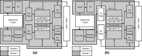
FIGURE 6.11 Two spheres of replication for an SRT processor. The shaded box in (a) shows a sphere of replication that includes the entire SMT pipeline shown in Figure 6.10, except the first-level data and instruction caches (SRT-Memory). The shaded box in (b) shows a sphere of replication that excludes the architectural register file, the first-level data cache, and the first-level instruction cache (SRT-Register). Reprinted with permission from Reinhardt and Mukherjee [10]. Copyright © 2000 IEEE.
![]() Stores. The output comparator must verify the address and data of every committed store before it forwards it outside the sphere of replication. One can use an ordered, noncoalescing store buffer shared between the redundant threads to synchronize and verify store values as they retire in program order from the RUU/LSQ. Each thread has an independent tail pointer into the buffer. If a thread finds its tail entry uninitialized, it writes the address and data value of its store into the entry. The second thread will find this entry initialized, so it will compare its address and data with the existing values. On a match, the entry is marked as verified and issued to the data cache. A mismatch indicates a fault. In this implementation, misspeculated stores never send their data outside the sphere of replication, so they do not need checking. To provide each thread with a consistent view of memory, the store buffer forwards data to subsequent loads only if the store has retired in the thread issuing the load.
Stores. The output comparator must verify the address and data of every committed store before it forwards it outside the sphere of replication. One can use an ordered, noncoalescing store buffer shared between the redundant threads to synchronize and verify store values as they retire in program order from the RUU/LSQ. Each thread has an independent tail pointer into the buffer. If a thread finds its tail entry uninitialized, it writes the address and data value of its store into the entry. The second thread will find this entry initialized, so it will compare its address and data with the existing values. On a match, the entry is marked as verified and issued to the data cache. A mismatch indicates a fault. In this implementation, misspeculated stores never send their data outside the sphere of replication, so they do not need checking. To provide each thread with a consistent view of memory, the store buffer forwards data to subsequent loads only if the store has retired in the thread issuing the load.
![]() Cached load addresses. Although cached data and instruction fetch addresses leave the sphere of execution, they do not affect the architectural state of the machine, so they do not require checking. If a faulty address leads to an incorrect load value or instruction, any resulting error will be detected via other output comparison checks before affecting architectural state outside the sphere. It will be seen later that allowing one thread to issue cache fetches early (and without output comparison), effectively prefetching for the other thread, is critical to the efficiency in SRT processors.
Cached load addresses. Although cached data and instruction fetch addresses leave the sphere of execution, they do not affect the architectural state of the machine, so they do not require checking. If a faulty address leads to an incorrect load value or instruction, any resulting error will be detected via other output comparison checks before affecting architectural state outside the sphere. It will be seen later that allowing one thread to issue cache fetches early (and without output comparison), effectively prefetching for the other thread, is critical to the efficiency in SRT processors.
![]() Uncached load addresses. Unlike cached loads, uncached loads typically have side effects in I/O devices outside the sphere of replication, so these addresses must be checked. However, unlike stores, uncached load addresses must be compared before the load commits. Fortunately, in most processors, uncached loads issue nonspeculatively and only after all prior loads and stores commit. Also, no load or store after the uncached load in program order can issue until the uncached load commits. Thus, an uncached load can simply stall in the execute stage until the corresponding instruction for the other thread arrives, at which point the addresses can be compared. An undetected fault could occur if an uncached load address was erroneously classified as cached and allowed to proceed without being checked. Adequate precautions must be taken to prevent this specific case, such as additional physical address cacheability checks.
Uncached load addresses. Unlike cached loads, uncached loads typically have side effects in I/O devices outside the sphere of replication, so these addresses must be checked. However, unlike stores, uncached load addresses must be compared before the load commits. Fortunately, in most processors, uncached loads issue nonspeculatively and only after all prior loads and stores commit. Also, no load or store after the uncached load in program order can issue until the uncached load commits. Thus, an uncached load can simply stall in the execute stage until the corresponding instruction for the other thread arrives, at which point the addresses can be compared. An undetected fault could occur if an uncached load address was erroneously classified as cached and allowed to proceed without being checked. Adequate precautions must be taken to prevent this specific case, such as additional physical address cacheability checks.
Output Comparison in SRT-Register
The second sphere of replication (Figure 6.11b) does not contain the register file (SRT-Register), so it requires output comparison on values sent to the register file—i.e., on register write-backs of committed instructions. As with stores, both the address (register index) and value must be verified. Register write-back comparison could be done as instructions retire from the RUU. However, forcing every instruction to wait for its equivalent from the other thread significantly increases RUU occupancy. Since the RUU is a precious resource, one could instead use a register check buffer, similar to the store buffer, to hold results from retired but unmatched instructions. The first instance of an instruction records its result in the buffer. When the corresponding instruction from the other thread leaves the RUU, the index and value are compared and, if they match, the register file is updated.
As with the store buffer, results in the register check buffer must be forwarded to the subsequent instructions in the same thread to provide a consistent view of the register file. The design can avoid complex forwarding logic by using the separate per-thread register files of the SMT architecture as “future files” [15]. That is, as each instruction retires from the RUU, it updates the appropriate per-thread register file, as in a standard SMT processor. This register file then reflects the up-to-date but unverified register contents for that redundant thread. As register updates are verified and removed from the register check buffer, they are sent to a third register file, which holds the protected, verified architectural state for the user-visible thread.
Having a protected copy of the architectural register file outside the sphere of replication simplifies fault recovery on an output mismatch, as the program can be restarted from the known good contents of the register file (as in the IBM Z-series microprocessors [13]). However, this benefit requires the additional costs of verifying register updates and protecting the register file with ECC or similar coverage. Although the register check buffer is conceptually similar to the store buffer, it must be significantly larger and must sustain higher bandwidth in updates per cycle to avoid degrading performance.
6.9.4 Input Replication in an SRT Processor
Inputs to the sphere of replication must be handled carefully to guarantee that both execution copies follow precisely the same path. Specifically, corresponding operations that input data from outside the sphere must return the same data values in both redundant threads. Otherwise, the threads may follow divergent execution paths, leading to differing outputs that will be detected and handled as if a hardware fault occurred. As with output comparison, the sphere of replication identifies values that must be considered for input replication: those that cross the boundary into the sphere.
Input Replication in SRT-Memory
For the first sphere of replication (SRT-Memory, Figure 6.11a), four kinds of inputs enter the sphere:
![]() Instructions. If the contents of the instruction space do not vary with time, then unsynchronized accesses from redundant threads to the same instruction address will return the same instruction without additional mechanisms. Updates to the instruction space require thread synchronization, but these updates already involve system-specific operations to maintain instruction-cache consistency in current processors. These operations can be extended to enforce a consistent view of the instruction space across redundant threads.
Instructions. If the contents of the instruction space do not vary with time, then unsynchronized accesses from redundant threads to the same instruction address will return the same instruction without additional mechanisms. Updates to the instruction space require thread synchronization, but these updates already involve system-specific operations to maintain instruction-cache consistency in current processors. These operations can be extended to enforce a consistent view of the instruction space across redundant threads.
The instruction replication itself can be implemented in a couple of ways. One possibility would to replicate instructions directly from the instruction cache but to allow unsynchronized access to it from both threads [10]. Another possibility would be to forward retired instructions from the leading thread to the trailing thread’s fetch unit [6]. The latter is very precise because only the committed instruction stream is forwarded to the trailing thread, thereby avoiding any branch misprediction in the trailing thread. In fact, a branch misprediction in the trailing thread in this case would be flagged as an error. In effect, the branch direction and address computation logic for the trailing thread acts as an output comparator.
![]() Cached load data. Corresponding cached loads from replicated threads must return the same value to each thread. Unlike instructions, data values may be updated by other processors or by DMA I/O devices between load accesses. An out-of-order SRT processor may also issue corresponding loads from different threads in a different order and in different cycles. Because of speculation, the threads may even issue different numbers of loads. Later in this section, two mechanisms for input replication for cached load data—active load address buffer (ALAB) and load value queue (LVQ)—are described.
Cached load data. Corresponding cached loads from replicated threads must return the same value to each thread. Unlike instructions, data values may be updated by other processors or by DMA I/O devices between load accesses. An out-of-order SRT processor may also issue corresponding loads from different threads in a different order and in different cycles. Because of speculation, the threads may even issue different numbers of loads. Later in this section, two mechanisms for input replication for cached load data—active load address buffer (ALAB) and load value queue (LVQ)—are described.
![]() Uncached load data. As with cached load data, corresponding loads must return the same value to both threads. Because corresponding uncached loads must synchronize to compare addresses before being issued outside the sphere of replication, it is straightforward to maintain synchronization until the load data return and then replicate that value for both threads. Other instructions that access nonreplicated, time-varying state, such as the Alpha rpcc instruction that reads the cycle counter, are handled similarly.
Uncached load data. As with cached load data, corresponding loads must return the same value to both threads. Because corresponding uncached loads must synchronize to compare addresses before being issued outside the sphere of replication, it is straightforward to maintain synchronization until the load data return and then replicate that value for both threads. Other instructions that access nonreplicated, time-varying state, such as the Alpha rpcc instruction that reads the cycle counter, are handled similarly.
![]() External interrupts. Interrupts must be delivered to both threads at precisely the same point in their execution. Three solutions are possible. The first solution forces the threads to the same execution point by stalling the leading thread until the trailing thread catches up and then delivers the interrupt synchronously to both threads. The second solution delivers the interrupt to the leading thread, records the execution point at which it is delivered (e.g., in committed instructions since the last context switch), and then delivers the interrupt to the trailing thread when it reaches the identical execution point. The third solution rolls both threads back to the point of the last committed register write. Rolling back may, however, be difficult if memory state is committed and exposed outside the sphere of replication.
External interrupts. Interrupts must be delivered to both threads at precisely the same point in their execution. Three solutions are possible. The first solution forces the threads to the same execution point by stalling the leading thread until the trailing thread catches up and then delivers the interrupt synchronously to both threads. The second solution delivers the interrupt to the leading thread, records the execution point at which it is delivered (e.g., in committed instructions since the last context switch), and then delivers the interrupt to the trailing thread when it reaches the identical execution point. The third solution rolls both threads back to the point of the last committed register write. Rolling back may, however, be difficult if memory state is committed and exposed outside the sphere of replication.
Input Replication in SRT-Register
As with output comparison, moving the register file outside the sphere means that additional values cross the sphere boundary. In the case of input replication, it is the register read values that require further consideration. However, each thread’s register read values are produced by its own register writes, so corresponding instructions will receive the same source register values in both threads in the absence of faults (and assuming that all other inputs are replicated correctly). In fact, many source register values are obtained not from the register file but by forwarding the results of earlier uncommitted instructions from the RUU (or from the “future file” as discussed in the previous section). Hence, input replication of register values requires no special mechanisms even when the register file is outside the sphere of replication.
6.9.5 Input Replication of Cached Load Data
Input replication of cached load data is problematic for both SRT-Memory and SRT-Register implementations because data values can be modified from outside the processor. For example, consider a program waiting in a spin loop on a cached synchronization flag to be updated by another processor. The program may count the number of loop iterations in order to profile wait times to adaptively switch synchronization algorithms. To prevent redundant threads from diverging, both threads must spin for an identical number of iterations. That is, the update of the flag must appear to occur in the same loop iteration in each thread, even if these corresponding iterations are widely separated in time. Simply invalidating or updating the cache may cause the leading thread to execute more loop iterations than the trailing thread. Hence, special attention needs to be given to input replication of cached data. Here two mechanisms for input replication of cached load data, the ALAB and the LVQ, are described.
Active Load Address Buffer
The ALAB provides correct input replication of cached load data by guaranteeing that corresponding loads from redundant threads will return the same value from the data cache. To provide this guarantee, the ALAB delays a cache block’s replacement or invalidation after the execution of a load in the leading thread until the retirement of the corresponding load in the trailing thread.
The ALAB itself comprises a collection of identical entries, each containing an address tag, a counter, and a pending-invalidate bit. When a leading thread’s load executes, the ALAB is searched for an entry whose tag matches the load’s effective address; if none is found, a new entry is allocated. Finally, the entry’s counter is incremented to indicate an outstanding load to the block. When a trailing thread’s load retires, the ALAB is again searched and the matching entry’s counter is decremented.
When a cache block is about to be replaced or invalidated, the ALAB is searched for an entry matching the block’s address. If a matching entry with a nonzero count is found, the block cannot be replaced or invalidated until all the trailing thread’s outstanding accesses to the block have completed. At this point, the counter will be zero and the block can be released. To guarantee that the counter eventually reaches zero, the cache sets the ALAB entry’s pending-invalidate bit to indicate that it is waiting; leading-thread loads that attempt to increment an entry with a set pending-invalidate bit are stalled. Because the trailing thread can always make forward progress, the outstanding loads will eventually complete. Although the block for which the cache receives the invalidation request cannot be immediately invalidated, the cache can still send an acknowledgement for the invalidation request. However, depending on the memory consistency model, the processor may have to stall other memory requests until the corresponding ALAB counter reaches zero.
The ALAB must reliably track every outstanding load and therefore cannot evict a nonzero ALAB entry. A leading-thread load must stall if it cannot allocate a new entry due to ALAB mapping conflicts or if it would increment the entry’s counter beyond the maximum value. Leading-thread stalls may lead to a deadlock. The processor can detect this deadlock condition by recognizing when (1) the trailing thread has caught up to the leading thread and (2) the leading thread’s oldest instruction is a load stalled because it cannot perform its ALAB increment. In this case, the processor must flush the leading thread from the pipeline (as on a misspeculation) and decrement the ALAB counters corresponding to executed but squashed loads. The stalled load can then reissue; because the trailing thread has committed all outstanding loads, it is guaranteed not to stall on the ALAB increment. Evaluation of an SRT processor by Reinhardt and Mukherjee [10] showed that a 64-entry, fully associative ALAB with 7-bit counters avoids this deadlock entirely across all their benchmarks.
Load Value Queue
The LVQ is an alternate mechanism to implement input replication of cached load values. Compared to the ALAB, the LVQ is much simpler to implement. In this mechanism, one of the redundant threads is designated as a leading thread and the other one as a trailing thread. Only the leading thread issues cached loads to the data cache outside the sphere of replication. When a cached load commits, the leading thread sends the load’s address and value to the trailing thread via the LVQ, which is a first-in first-out buffer.
The LVQ can be read out both in program order and out-of-order. In the in-order implementation, the trailing thread performs loads in program order and nonspeculatively. The loads in the trailing thread proceed through the regular processor pipeline. However, instead of probing the data cache, the trailing thread waits for its corresponding load address and value from the leading thread to show up at the head of the LVQ. Input replication is guaranteed because the trailing thread receives the same value for the load that the leading thread used.
Alternatively, loads from the trailing thread can issue out of order. In this case, the leading thread must attach tags to the loads it inserts in the LVQ and must transmit these tags to the trailing thread. One way to achieve this is to forward the instruction tags of the leading thread to the replicated instructions of the trailing thread. This is easy to do in the second instruction replication mechanism outlined earlier (see Input Replication in an SRT Processor, p. 232).
Figure 6.12 shows the lookup operation performed in either an in-order or an out-of-order LVQ. Typically, a load would look up both a data cache and a store queue simultaneously to see the structure that has the most recent value required by the load instruction. This is the path followed by loads from a leading thread. However, loads from the trailing thread simply look up the LVQ, bypass the data cache and store queue, and forward their data back to the registers waiting for the loaded values.

FIGURE 6.12 Lookup operation of an LVQ in an SRT processor. The figure shows only the case when a leading thread’s load hits in the data cache or the store queue.
The LVQ provides a couple of additional advantages to the SRT implementation. The LVQ reduces the pressure on the data cache ports because, unlike the ALAB design, only one thread probes the data cache. Additionally, the LVQ can accelerate fault detection of faulty addresses by comparing the effective address of the leading thread from the LVQ with the effective address of the trailing thread.
6.9.6 Two Techniques to Enhance Performance of an SRT Processor
An SRT processor can improve its performance using one thread to improve cache and branch prediction behavior for the other thread. Two such mechanisms—slack fetch and branch outcome queue—that achieve this performance improvement are described. During execution, these mechanisms allow the trailing thread to use fewer pipeline resources, such as compute bandwidth and pipeline structure space, which improves the overall performance of an SRT processor. Hence, typically an SRT processor—running a single logical program replicated as redundant threads—would complete the logical program faster than the underlying SMT pipeline would when running two independent copies of the same program.
Slack Fetch
The slack fetch mechanism tries to maintain a constant slack of instructions between the leading and the trailing threads. Ideally, branches from the trailing thread should probe the branch predictor after the corresponding branch from the leading thread has executed and updated the predictor. Similarly, accesses from the trailing thread should probe the instruction and data caches after the corresponding accesses from the leading thread have incurred any misses and brought in the cache blocks. Slack fetch achieves this by forcing instructions from the trailing thread to execute later in time than the corresponding instructions from the leading thread.
In one implementation, slack fetch can be implemented using a signed counter that is decremented when the (predesignated) leading thread commits an instruction and can be incremented when the (predesignated) trailing thread commits an instruction. The counter is initialized at reset to the target slack. By adding the counter’s value in each cycle to the trailing thread’s instruction count, the ICount fetch policy (see A Simultaneous Multithreaded Processor, p. 228) favors the leading thread until the target slack is reached, automatically guiding the fetch stage to maintain the desired slack.
Alternatively, slack fetch can also be implemented using the second instruction replication mechanism described earlier (see Input Replication in an SRT Processor, p. 232). By forwarding committed instructions from the leading thread to the fetch unit of the trailing thread, an inherent slack is introduced, such that cache misses incurred by the leading thread’s instructions are already resolved before the corresponding trailing-thread loads probe the cache or LVQ, as the case may be. In this implementation, the trailing thread’s instructions can be prioritized over that of the leading thread to help reduce pressure pipeline structures, such as the store queue.
Branch Outcome Queue
The branch outcome queue reduces misspeculation more directly and effectively than the slack fetch mechanism. This technique uses a hardware queue to deliver the leading thread’s committed branch outcomes (branch PCs and target addresses) to the trailing thread. In the fetch stage, the trailing thread uses the head of the queue much like a branch target buffer, reliably directing the thread down the same path as the leading thread. Consequently, in the absence of faults, the trailing thread’s branches never misfetch or mispredict and the trailing thread never misspeculates. To keep the threads in sync, the leading thread stalls in the commit stage if it cannot retire a branch because the queue is full. The trailing thread stalls in the fetch stage if the queue becomes empty.
Alternatively, if the committed instructions from the leading thread are forwarded to the fetch stage of the trailing thread, then one does not need a branch outcome queue. This is because the trailing thread receives the precise committed path of the leading thread, which achieves the same effect as the branch outcome queue.
6.9.7 Performance Evaluation of an SRT Processor
Mukherjee et al. evaluated the performance of an SRT implementation on a commercial SMT processor using all the 18 SPEC95 benchmarks [6]. They showed that on average SRT degrades performance over running just the single thread (without any redundant copies) by 32%. SRT techniques improve performance over running two redundant copies of the same program (without any input replication or output comparison) by 11%. This improvement is due to the positive effects of the LVQ and instruction replication in the SRT processor. The LVQ reduces data cache misses in two ways: the trailing thread cannot miss because it never directly accesses the cache and the leading thread thrashes less in “hot” cache sets because it does not compete with the trailing thread. They found that their SRT processor, on average, has 68% fewer data cache misses than the base processor running redundant copies of two threads.
Mukherjee et al. also found that output comparator for stores is one of the key bottlenecks in the SRT design. The store comparator increases the lifetime of a leading thread’s stores, which must now wait for the corresponding stores from the trailing thread to show up before they can retire. On average, for one logical thread, the store comparator increased the lifetime of a leading thread’s store by 39 cycles. Eighteen of these cycles represent the minimum latency for the trailing-thread store to fetch and execute; the extra 21 cycles came from queuing delays in the instruction replication mechanism and processor pipeline.
Consequently, increasing the size of the store queue has significant impact on performance because this allows other stores from the leading thread to make progress. A per-thread store queue (with 64 entries per thread) instead of a combined store queue for both leading and trailing threads improved performance by 4%, bringing the degradation to only roughly 30%. Completely eliminating the impact of the store comparator perhaps with an even bigger store queue would improve performance by another 5% and reduce the performance degradation to 26%.
In a multicore processor with SMT threads, turning on SRT also reduces the overall throughput of the processor itself since half the threads are running redundantly instead of contributing to the overall performance. By turning on SRT, the benefits of a second SMT thread running on the same core are lost. SRT recovers some of this performance loss because of reduced pressure on the memory system (since only one thread accesses memory) and branch predictor (since only one thread gets its predictions from the branch predictor). However, a better underlying SMT implementation will usually cause less penalty in latency (i.e., increase in execution time of a single program) from SRT. But a better SMT implementation would also cause higher degradation in throughput from a multicore SRT processor.
6.9.8 Alternate Single-Core RMT Implementation
Rotenberg’s single-core RMT implementation (AR-SMT) design [11] is an alternate implementation of RMT within a single-core SMT processor. AR-SMT incorporates two redundant threads: the “active,” or A-thread, and the “redundant,” or R-thread. Committed register write-backs and load values from the A-thread are placed in a delay buffer, where they serve as the alternate execution stream against which R-thread results are checked and predictions to eliminate speculation on the R-thread. Thus, the delay buffer combines SRT’s register check buffer and branch outcome queue. In addition, the R-thread uses the delay buffer as a source of value predictions to speculate past data dependencies.
AR-SMT is one point in the SRT design space; its sphere of replication is the SRT-Register’s sphere in which the register file resides outside. In AR-SMT, the R-thread register file serves as the architectural file: register write-back values are verified before updating the R-thread registers, and the R-thread file is considered to be a valid checkpoint for fault recovery. As with the register files in SRT-Register, the A-thread register file serves only to bypass uncommitted register updates still in the delay buffer. Thus, replication does not provide fault coverage for the R-thread register file, so this register file must be augmented with an alternate coverage technique, such as ECC. Otherwise, a fault in an R-thread register value would lead to a mismatch in A-thread and R-thread results. AR-SMT would correctly detect this fault but may improperly recover by restarting from the corrupted R-thread register file contents.
Fundamentally, for fault detection using redundant computation, one needs two redundant computation units or threads and an output comparator. Typically, these are three distinct components of a fault detecting system. AR-SMT, however, combines the R-thread with the output comparator, which potentially saves hardware but results in reduced fault coverage compared to an SRT-style design.
AR-SMT also varies significantly from the SRT designs described above since in AR-SMT entire main memory is inside the sphere of replication. This scheme provides better memory fault detection than ECC. Nevertheless, doubling the physical memory of a system can be very expensive. Because the R-stream has a separate memory image distinct from that of the A-stream, AR-SMT requires modifications in the OS to manage the additional address mappings needed to replicate the address space. To make this replication simpler, the design disables redundant threading on OS calls, leaving kernel code vulnerable to transient hardware faults.
6.10 RMT in a Multicore Architecture
This section discusses how RMT can be implemented in a chip multiprocessor (CMP), more popularly known today as multicore processors. This is referred to as chip-level redundant threading or CRT. CRT achieves core Lockstepping’s permanent fault coverage while maintaining SRT’s low-overhead output comparison and efficiency optimizations. The basic idea of CRT is to generate logically redundant threads, as in SRT, but to run the leading and trailing threads on separate processor cores, as shown in Figure 6.13 [6,7].
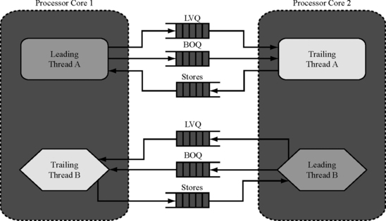
FIGURE 6.13 Block diagram of a CRT implementation using two cross-coupled processor cores. BOQ = branch outcome queue.
The trailing threads’ LVQs and branch outcome queues now receive inputs from leading threads on the other processor core. Similarly, the store comparator, which compares store instructions from redundant threads, receives retired stores from the leading thread on one processor core and trailing thread on another processor core. To forward inputs to the LVQ, the branch outcome queue, and the store comparator, moderately wide datapaths between the processors are needed. It may be possible to lay out the processor cores on the die such that such datapaths do not traverse long distances. These datapaths will be outside the sphere of replication and may require protection with some form of information redundancy, such as parity.
CRT processors provide two advantages over Lockstepped microprocessors. First, in Lockstepped processors, all processor output signals must be compared for mismatch, including miss requests from the data and instruction caches. This comparison is in the critical path of the cache miss and often adversely affects performance. More generally, the output comparator must interpose on every logical signal from the two processor cores, check for mismatch, and then forward the signal outside the sphere of replication. Of course, a CRT processor incurs latency to forward data to the LVQ, the branch outcome queue, or the store comparator, but these queues serve to decouple the execution of the redundant threads and are not generally in the critical path of data accesses.
Second, CRT processors can run multiple independent threads more efficiently than Lockstepped processors. By pairing leading and trailing threads of different programs on the same processor, the overall throughput can be maximized. Atrailing thread rarely or never misspeculates, freeing resources for the other application’s leading thread. Additionally, in our implementation, trailing threads do not use the data cache or the load queue, freeing up additional resources for leading threads. Evaluation of Mukherjee et al. shows that such a CRT processor performs similarly to core Lockstepping for single-program runs (in non-SMT mode) but can outperform Lockstepping by 13% on average (with a maximum improvement of 22%) for multithreaded program runs.
6.11 DIVA: RMT Using Specialized Checker Processor
As discussed earlier, in both the SRT and CRT implementations, the trailing thread consumes significantly less pipeline bandwidth than the leading thread. Austin took this idea further by designing a custom lightweight checker core that is paired up with a normal processor core. Austin calls this the Dynamic Implementation Verification Architecture (DIVA) [1].
To understand how DIVA works, let us look at the following sequence of two dynamic instructions: (Inst1) R1 = R2 + R3 and (Inst2) R5 = R1 + R4. The instruction Inst1—executed first—reads source registers R2 and R3, computes the sum of the values in the two registers, and then writes them back into destination register R1. The second instruction Inst2 does the same—reads values in source registers R1 (just produced) and R4, computes the sum of these values, and then writes them back into destination register R4. To verify that this sequence of instructions executes correctly, two properties must be ensured:
![]() Given the source register values, each add operation computes the result value correctly. For example, given the source register values for Inst2, it must be verified that the add operation actually computes the value in R5 correctly.
Given the source register values, each add operation computes the result value correctly. For example, given the source register values for Inst2, it must be verified that the add operation actually computes the value in R5 correctly.
![]() The source register values flow correctly and without errors to every instruction. For example, it must be verified that Inst2 receives the correct values for R1 and R4. In a pipelined implementation with pipeline bypasses, the value in R1 may flow directly from Inst1 to Inst2 without going through the architecture storage register R1. In this case, it must be verified that this bypass flow is correct.
The source register values flow correctly and without errors to every instruction. For example, it must be verified that Inst2 receives the correct values for R1 and R4. In a pipelined implementation with pipeline bypasses, the value in R1 may flow directly from Inst1 to Inst2 without going through the architecture storage register R1. In this case, it must be verified that this bypass flow is correct.
Figure 6.14 shows how DIVA implements these two verification steps using separate checker pipelines: the CHKcomp pipeline that verifies the first property and the CHKcomm pipeline that verifies the second. Because the two pipelines are simpler than the main processor core, Austin argues that they can run at a much slower frequency, allowing a much simpler pipeline implementation than the main processor. Using a performance simulator of the DIVA architecture, Austin has also shown that on a set of selected SPEC benchmarks, the DIVA checker slows down the main processor core on average by only 3% (with a maximum degradation of 15%).

The CHKcomp Pipeline
The CHKcomp pipeline verifies that an instruction has been executed correctly by the main processor. For a given instruction executed in the main processor core, the CHKcomp pipeline receives the instruction, the source operand values, and the result operation. In the EXECUTE stage, the CHKcomp pipeline recomputes the result based on the source operand values it receives. Then, in the COMPARE stage, it compares the result value just generated with the result value it receives from the main processor. If the compared values match, then the DIVA checker can certify that the values have been computed correctly. If the compared values do not match due to a particle strike in either the main processor or the DIVA checker, it will be flagged as an error.
The CHKcomp pipeline does not have any dependences. It simply computes the result value based on the incoming source operand values. Consequently, as many CHKcomp pipelines can be instantiated as may be necessary to match the instruction throughput of the main processor. For example, if the main processor can commit four instructions in a DIVAchecker cycle, one can potentially instantiate four CHKcomp pipelines to avoid slowing down the main processor. This allows the DIVA CHKcomp pipeline to match the main processor’s bandwidth even with a much slower clock.
The CHKcomm Pipeline
The CHKcomm pipeline verifies that operand values flow correctly from one instruction to another. Like the CHKcomp pipeline, it also receives instructions with their source operands. In the READ stage, it reads the values of these source operands from its own architectural register file. The CHECK stage verifies that the source operands received and source operands read from the register file match. For example, for Inst1, the CHKcomm pipeline will read R2 and R3 from its own register file and verify that the incoming source operand values match these. Then, in the cycle after the READ stage, the CHKcomm pipeline will write back the result value into the destination register. For Inst1, the pipeline will write back R1’s value it received from the main processor into the register file.
Inst2, however, poses a little complication since it must receive the value of R1 from Inst1. Hence, the pipeline needs to implement a bypass path, so that Inst1’s result value is forwarded as a source operand for Inst2. Thus, the CHECK stage can receive the source operands either from the register file or from the bypass path. In either case, however, it simply compares the source operands while the write-back of the result operand proceeds in parallel.
Unlike the CHKcomp pipeline, replicating the CHKcomm pipeline poses some difficulties because of the bypass operations. To match the instruction bandwidth of the main processor, the CHKcomm pipeline can be replicated multiple times. But each of these pipelines must implement a complicated bypass network that allows values to be forwarded arbitrarily across any of these pipelines. For example, if the main processor can commit four instructions per DIVAchecker cycle, then four CHKcomm pipelines can be implemented to avoid slowing down the main processor. However, if Inst1 is executed on CHKcomm pipeline 1 and Inst2 is executed on CHKcomm 2, then Inst1’s result value must be forwarded from pipeline 1 to pipeline 2. In the general case, Inst1’s result may need to be forwarded to all of the other three pipelines. Such bypass paths may make it challenging to scale the CHKcomm pipeline to match the main processor bandwidth.
Trade-offs in the DIVA Processor
The DIVA architecture poses two significant advantages beyond detecting transient faults. First, it can detect both permanent faults and design errors in the main processor. In contrast, in an SRT processor, permanent faults on structures shared between the redundant threads may go undetected. A CRT processor would detect such permanent faults, but since the redundant cores would typically be replicated, it will not be able catch design errors. Also, DIVA does not require an underlying SMT architecture like an SRT processor.
DIVA does, however, pose a few other challenges in its design. First, in the presence of I/O devices or multiple processors, the DIVA architecture can detect false transient faults due to external memory writes. On detecting a fault, the DIVA checker proposes to execute the instruction entirely on the DIVA checker itself. This property can potentially lead to a livelock if the external agent (I/O device or processor) continues to provide the same external memory write but with different values. It should be possible to augment DIVA with an ALAB or LVQ to avoid this problem.
Second, to guarantee forward progress in the presence of permanent faults in the main processor, DIVA assumes that the checker is always correct and proceeds using the checker’s result in the case of a mismatch. Also, for uncached loads and stores that cannot be executed twice, DIVA relies on the checker to execute them nonredundantly. In these cases, faults in the checker itself—including transient faults—must be detected or avoided through alternative techniques. For example, Austin suggests that design errors could be avoided by formally verifying the checker. Alternatively, the DIVA checkers can be replicated and run in Lockstep to detect faults in the checker itself.
6.12 RMT Enhancements
Enhancements in the RMT design are an active area of research today. The primary goal of most RMT optimizations is to reduce the performance degradation of a single program caused by the redundant thread. Such enhancements may offer reduced fault coverage in some cases. That may still be worthwhile if the SER is within a product’s SDC and DUE budgets.
An RMT implementation’s performance degradation can be reduced using three broad techniques: relaxing constraints on input replication, relaxing constraints on output comparison, and partial RMT techniques that avoid executing some number of instructions in one of the redundant threads.
6.12.1 Relaxed Input Replication
Input replication, such as of that of load values, may sometimes prevent the trailing thread from making progress. This could be because the communication latency between the leading and the trailing threads is high. Alternatively, this could also be because the trailing thread starts to march ahead of the leading thread, which could happen in some RMT designs. Load value predictors—explored in microarchitecture research in the past decade—can help the trailing thread make progress without waiting for its inputs from the leading thread’s LVQ, for example.
6.12.2 Relaxed Output Comparison
Output comparison necessitates committed instructions or selected instructions of both the threads to be available for comparison. This can cause performance degradation if this comparison causes one of the threads to be held up. The SRT and CRT implementations already relax this constraint somewhat by requiring output comparison only on selected instructions, such as stores, without increasing a processor’s SDC rate.
Even in an SRT implementation, the leading thread can be held up by the trailing thread. This may disallow the leading thread to make further progress possibly because structures, such as the store queue, may have filled up. To allow the leading thread to make progress, an SRT implementation could choose to not compare stores when the leading thread cannot make progress. This would incur a higher SER, which could be computed through an AVF analysis.
Vijaykumar et al. [21] proposed and Gomaa et al. [4] refined a scheme called dependence-based checking elision (DBCE) to reduce the number of instructions that needs to be checked for faults. As instructions execute, a transient fault propagates through the instruction chains via either its control flow (e.g., branches) or its dataflow (e.g., registers). As instructions execute, the DBCE scheme builds short sequences of instructions to create these dependence chains. Given such a DBCE chain, only the last instruction in the chain needs to be checked for faults. Instructions that mask faults, such as OR instruction, cannot be part of such a chain unless they are the last instruction of a chain. Otherwise, they can mask faults, whose effect may not be captured by the last instruction in a DBCE chain. Alternatively, masking instructions can be allowed to be part of a chain but that will reduce the fault coverage of the RMT implementation.
Alternatively, a transaction-based implementation can offer significantly greater flexibility in fault detection but without sacrificing fault coverage. In a transaction-based system, a program is constructed as a series of transactions, where each transaction may consist of one or more instructions. The result of a transaction is committed to the global state atomically at the end of a transaction. By running transactions redundantly and comparing their outputs before the transaction commit point, one can detect faults in such transactions. This requires output comparison only when a transaction commits, thereby reducing the need for both redundant threads to be synchronized at every instruction.
6.12.3 Partial RMT
Another way to reduce performance degradation from an RMT implementation is to avoid executing selected regions of one of the redundant threads. By not executing instructions from one of the threads, for example, an SRT implementation can free up execution resources for the other thread. There have been a number of proposals that exploit this:
![]() Instruction reuse. Sodani and Sohi proposed instruction reuse to expedite the execution of a single program [16]. Sodani and Sohi created an instruction reuse buffer that tracks one or more instructions’ input and output values. If an instruction or a sequence of instructions is executed again and can be matched against the instructions present in the reuse buffer, then the pipeline can simply obtain the output of the instructions without executing them. In an SRT implementation, the contents of the reuse buffer can be updated after the output comparator certifies that an instruction is fault free. In subsequent executions, the trailing thread can use values being passed to it by the leading thread (e.g., via an RVQ) to probe the reuse buffer, obtain the result values in case of a hit, and thereby avoid executing the instruction itself. Parashar et al. [8] and Gomaa and Vijaykumar [5] have explored variants of this scheme.
Instruction reuse. Sodani and Sohi proposed instruction reuse to expedite the execution of a single program [16]. Sodani and Sohi created an instruction reuse buffer that tracks one or more instructions’ input and output values. If an instruction or a sequence of instructions is executed again and can be matched against the instructions present in the reuse buffer, then the pipeline can simply obtain the output of the instructions without executing them. In an SRT implementation, the contents of the reuse buffer can be updated after the output comparator certifies that an instruction is fault free. In subsequent executions, the trailing thread can use values being passed to it by the leading thread (e.g., via an RVQ) to probe the reuse buffer, obtain the result values in case of a hit, and thereby avoid executing the instruction itself. Parashar et al. [8] and Gomaa and Vijaykumar [5] have explored variants of this scheme.
![]() Avoid execution of dynamically dead instructions. Parashar et al. [9] have proposed a scheme called SlicK that tracks backward slices of instructions in the leading thread to determine, and thereby eliminate, any dynamically dead instruction from the trailing thread. Recall that a dynamically dead instruction is one whose result will never be used by any instruction in future. For example, if register R1 is written by an instruction and subsequently overwritten by another instruction without any intervening writes to R1, then the first instruction that wrote R1 is dynamically dead. SlicK would potentially avoid executing any such dynamically dead instruction tracked through the architectural registers.
Avoid execution of dynamically dead instructions. Parashar et al. [9] have proposed a scheme called SlicK that tracks backward slices of instructions in the leading thread to determine, and thereby eliminate, any dynamically dead instruction from the trailing thread. Recall that a dynamically dead instruction is one whose result will never be used by any instruction in future. For example, if register R1 is written by an instruction and subsequently overwritten by another instruction without any intervening writes to R1, then the first instruction that wrote R1 is dynamically dead. SlicK would potentially avoid executing any such dynamically dead instruction tracked through the architectural registers.
![]() Store value prediction. In the basic SlicK implementation, all stores are compared to ensure full fault coverage. Only the dynamically dead instructions are not executed. Parashar et al. [9] enhanced this scheme further by using store value prediction. The enhanced SlicK implementation avoided executing any instruction leading up to a store, whose value could be predicted by a store predictor.
Store value prediction. In the basic SlicK implementation, all stores are compared to ensure full fault coverage. Only the dynamically dead instructions are not executed. Parashar et al. [9] enhanced this scheme further by using store value prediction. The enhanced SlicK implementation avoided executing any instruction leading up to a store, whose value could be predicted by a store predictor.
![]() Turn trailing thread off in high IPC regions. Another way to reduce the performance degradation of RMT is to completely turn off the trailing thread in certain regions of a program. These regions could be regions with high IPC, low AVF, or high power dissipation. Gomaa and Vijaykumar [5] studied a scheme in which they turned off the trailing thread (thereby reducing fault coverage and increasing AVF) during regions of a program they found to have high IPC. The key challenge of such a scheme is to recreate the correct state of the trailing thread from which it can be restarted. Gomaa and Vijaykumar recreated this state by forwarding architectural state updates from the leading to the trailing thread. Alternatively, one could use an RVQ or an LVQ to recover the trailing thread’s state as well since both these structures contain the updates to architectural state.
Turn trailing thread off in high IPC regions. Another way to reduce the performance degradation of RMT is to completely turn off the trailing thread in certain regions of a program. These regions could be regions with high IPC, low AVF, or high power dissipation. Gomaa and Vijaykumar [5] studied a scheme in which they turned off the trailing thread (thereby reducing fault coverage and increasing AVF) during regions of a program they found to have high IPC. The key challenge of such a scheme is to recreate the correct state of the trailing thread from which it can be restarted. Gomaa and Vijaykumar recreated this state by forwarding architectural state updates from the leading to the trailing thread. Alternatively, one could use an RVQ or an LVQ to recover the trailing thread’s state as well since both these structures contain the updates to architectural state.
6.13 Summary
In fault detection via redundant execution, identical copies of the same program are executed redundantly. The outputs of the redundantly executing streams are compared for mismatch. A mismatch signals a fault and can initiate a number of possible recovery actions.
The concept of the sphere of replication helps explain how such redundant execution streams work. The sphere of replication identifies the logical domain protected by the fault detection scheme. Any component within the sphere must be logically or physically replicated. Any output leaving the sphere of replication must be compared to check for mismatch and corresponding faults. The output comparator has also been referred to in the literature as the checker. Any inputs into the sphere of replication must be appropriately replicated and delivered to the correct points within the sphere.
There are two ways of performing such redundant execution: cycle-by-cycle Lockstepping or RMT. Lockstepping has been used for decades in mainframe systems, whereas RMT has been introduced in the past decade. RMT has also been referred to as loose Lockstepping. In Lockstepping, redundant streams are usually run on two separate, but identical, processor cores. The processor cores must have the exact same state in each cycle. Consequently, output comparison involves comparing the values of signals coming from each processor core in the sphere of replication. Lockstepping does not require any semantic information from these signals. Because both processor cores have the same state in each cycle, any pair of hardware signals from the redundant processor cores must have the exact same value in the absence of a fault. Inputs into the sphere must be replicated and delivered to both processor cores at the same cycle boundary.
The Stratus ftServer, Hewlett-Packard Himalaya, and the IBM Z-series machines are all Lockstepped. Nevertheless, the designs differ significantly in their spheres of replication, which affects the hardware overhead incurred by each design. The ftServer includes main memory in its sphere of replication, which implies that main memory is replicated for each redundant execution stream. Himalaya’s sphere of replication does not include main memory. Instead, Himalaya compares outputs arising from the processors themselves. The Z-series processors replicate processor pipelines on the processor chip itself. The processor pipelines constitute the sphere of replication in the Z-series processors.
In contrast, in RMT, only committed instructions from redundant streams are compared for mismatch. The underlying hardware contexts running the redundant threads can be either processor cores or hardware threads in a multithreaded processor. The hardware contexts running the redundant threads may not have the same state in the same cycle. What outputs must be compared depends on the size of the sphere. If the sphere of replication includes processor cores and memory, then only outputs to I/O devices must be compared for mismatch. Inputs must be replicated carefully in an RMT system since the underlying redundant contexts have different states in the same cycle. Inputs are typically delivered at the same committed instruction boundary, which ensures that the redundant execution streams do not diverge.
The Marathon Endurance Server and the Hewlett-Packard NSAA implement RMT with similar spheres of replication. Both include memory and processors in their spheres of replication and compare I/O outputs for mismatches. The machines, however, differ significantly in the way they do input replication. The Marathon Endurance Server raises an interrupt after a predetermined number of committed instructions. The two instruction streams coordinate and determine a point to replicate inputs. In NSAA, however, the instruction streams explicitly poll the machine for input replication requests and post requests to obtain the replicated inputs. This requires modifications to the OS, which is possible because the NSAA runs its own custom OS, unlike the Endurance Server that runs Windows, which is a commodity OS.
Other proposed RMT designs, such as SRT, CRT, and DIVA, implement RMT within a single chip. In SRT, the redundant threads are implemented within a single multithreaded processor core, whereas in CRT the redundant threads are executed on different processor cores on the same chip. In contrast, DIVA creates a specialized checker core to act as one of the redundant threads. Each of these designs offers different trade-offs and hardware overhead.
6.14 Historical Anecdote
Contributed by Dr. Phil Emma of IBM Corporation:
In a bold move in the early 1990s, IBM transitioned mainframe design over to CMOS. For the first time, IBM was going to build its large S390 Servers (now called “series”) using a new custom CMOS microprocessor. The internal name for this system was “Alliance,” signifying the joint “alliance” formed between research engineers and development engineers to create this processor.
I was given the role of leading the specification and design of the “R unit,” which was an entirely new unit that took a new approach toward RAS within the new context of CMOS. S390 historically featured “bulletproof” RAS required by many mainframe customers and particularly those in financial businesses. Our goal was to make each server generation more reliable than the previous generation. We wanted to catch as many faults as possible and to recover from as many errors as possible.
Historically, in our bipolar designs, checking circuitry was integral to the computation circuitry. Most combinational logic had integral parity prediction, and most state logic was encoded using fail-safe techniques and state checking. There were many registers put in for retaining state (to recover to), and all state was scannable. In those machines, the timing was not dominated by wire paths, and the powerful ECL logic was not very sensitive to capacitive loading, so these well-evolved techniques made sense.
CMOS, however, is extremely sensitive to loading, and in the new custom design, wire lengths were critical. Therefore, in a radical departure from what we had done in the past, we decided to merely replicate the processor (but not the cache). The pair of processors were operated as a single logical processor. Anew “R unit” verified—on a per-instruction basis—that both processors produced the same results. The R unit also maintained a “golden” (ECC-protected) checkpoint of all architected state. The R unit could effect recovery actions and log errors when they were found. It also contained lots of other odds and ends, time-of-day clocks, timers, service interfaces, trace arrays, etc.
The R unit was designed as a fully replicated and fully cross-checked “dual pipeline.” That is, in addition to doing bulletproof checking of the rest of the machine, it also did a bulletproof checking of itself. We estimated that the chip area overhead for having a redundant processor and an R unit was about 30%. By not putting parity prediction circuits into the processors, we kept their areas (hence wire-bound paths) and capacitive loadings small. This gave us a significant performance advantage for nearly the same area penalty, and an arguably smaller design effort.
People have conjectured why this was called the “R unit.” We do not know for sure. Charles Webb, the chief architect of the machine, started calling it the “R unit” from day 1. “R” never stood for anything. It was just a letter (like the I and E units). Many years after the fact, I have heard sales and marketing people say that it was the “Register” unit (because of all the checkpointing), the “Recovery” unit, or the “Reliability” unit. In reality, it was just the “R” unit, and “R” did not stand for anything.
Vijay Lund was a rising-star executive in charge of the project. Initially, it was clear that he was a little uncomfortable with having research engineers embedded in the development design team and more than a little uncomfortable (in those days) with having a researcher like me leading part of the design. Given our cultural differences, I fully understood this, and it was not an unreasonable point of view. But what was especially perplexing to all executives—and to Vijay—was that although we had two processors in there, we were using them like they were a single processor. Most executives had a very hard time accepting this as being the right approach.
Every time I bumped into Vijay (and most other executives), I would be asked how I knew that we are going to have errors at all in the silicon. This was a new technology. We had no evidence that we would have errors at all. Would it not be better to just forget about the R unit and run the chip as a dual-core chip? I would always tell them that they should think about RAS exactly like they thought about term life insurance. If they are extremely lucky, then it is a total waste of their money. Nonetheless, every time I would see Vijay, he would ask the same question. I think that he enjoyed teasing me to keep me on my toes.
One day I came into Vijay’s conference room to give my weekly status report to the management team. At the end of my presentation, Vijay said that he had finally figured out what “R” stood for. So I asked “What does ‘R’ stand for?” He said “It means Removable.” As I said before, Vijay knew how to keep a team on its toes.
References
Austin T.M. DIVA: A Reliable Substrate for Deep Submicron Microarchitecture Design. 32nd Annual International Symposium on Microarchitecture (MICRO). 1999:196–207.
Bernick D., Bruckert B., Vigna P.D., Garcia D., Jardine R., Klecka J., Smullen J. NonStop® Advanced Architecture. In: Proceedings. International Conferenceon Dependable Systems and Networks (DSN). Japan: Yakohama; June/July 2005:12–21.
Bissett T.D., Leveille P.A., Muench E., Tremblay G.A. Loosely-Coupled, Synchronized Execution, April 20,1999. United States Patent 5,896,523, issued
Gomaa M.A., Scarbrough C., Vijaykumar T.N., Pomeranz I. Transient Fault-Recovery for Chip Multiprocessors. Proceedings of 30th Annual International Symposium on Computer Architecture (ISCA). June 2003:98–109.
Gomaa M.A., Vijaykumar T.N. Opportunistic Fault Detection. 32nd Annual International Symposium on Computer Architecture (ISCA). June 2005:172–183. Madison, Wisconsin, USA
Mukherjee S.S., Kontz M., Reinhardt S.K. Detailed Design and Evaluation of Redundant Multithreading Alternatives. Proceedings of the 29th Annual International Symposium on Computer Architecture (ISCA). May 2002:99–110. Anchorage, Alaska, USA
Nair R., Smith J.E. Method and Apparatus for Fault-Tolerance Via Dual Thread Crosschecking, September 19, 2002. United States Patent Application, publication date
Parashar A., Gurumurthi S., Sivasubramaniam A. A Complexity-Effective Approach to ALU Bandwidth Enhancement for Instruction-Level Temporal Redundancy. 31st Annual International Symposium on Computer Architecture (ISCA). June 2004:376–386.
Parashar A., Gurumurthi S., Sivasubramaniam A. SlicK: Slice-Based Locality Exploitation for Efficient Redundant Multithreading. 12th Annual International Conference on Architectural Support for Programming Languages and Operating Systems (ASPLOS). October 2006:95–105.
Reinhardt S.K., Mukherjee S.S. Transient Fault Detection via Simultaneous Multithreading. 27th Annual International Symposium on Computer Architecture (ISCA). June 2000:25–36. Vancouver, British Columbia, Canada, USA
Rotenberg E. AR-SMT: A Microarchitectural Approach to Fault Tolerance in Microprocessors. 29th Annual Fault-Tolerant Computing Systems (FTCS). June 1999:84. Madison, Wisconsin, USA
Sieiorek D.P., Swarz R.S., Peters A.K. Reliable Computer Systems: Design and Evaluation. 1998.
Slegel T.J., Averill R.M., III., Check M.A., Giamei B.C., Krumm B.W., Krygowski C.A., Li W.H., Liptay J.S., MacDougall J.D., McPherson T.J., Navarro J.A., Schwarz E.M., Shum K., Webb C.F. IBM’s S/390 G5 Microprocessor Design. IEEE Micro. March/April 1999:12–23.
Slegel T.J., Pfeffer E., Magee J.A. The IBM eServer z990 Microprocessor. IBM Journal of Research and Development. May/July 2004;Vol. 48(No. 3/4):295–309.
Smith J.E., Pleszkun A.R. Implementing Precise Interrupts in Pipelined Processors. IEEE Transactions on Computers. May 1988;Vol. 37(No. 5):562–573.
Sodani A., Sohi G.S. Dynamic Instruction Reuse. 24th Annual International Symposium on Computer Architecture (ISCA). June 1997:194–205. Denver, Colorado, USA
Tullsen D.M., Eggers S.J., Emer J.S., Levy H.M., Lo J.L., Stamm R.L. Exploiting Choice: Instruction Fetch and Issue on an Implementable Simultaneous Multithreading Processor. 23rd Annual International Symposium on Computer Architecture (ISCA). May 1999:191–202.
Tullsen D.M., Eggers S.J., Levy H.M. Simultaneous Multithreading: Maximizing On-Chip Parallelism. 22nd Annual International Symposium on Computer Architecture (ISCA). June 1995:392–403. Italy
Somers J. Stratus ftServerc—Intel Fault Tolerant Platform. Intel Developer Forum. Fall 2002.
Spainhower L., Gregg T.A. IBM S/390 Parallel Enterprise Server G5 Fault Tolerance: A Historical Perspective. IBM Journal of Research and Development. September/November 1999;Vol. 43(No. 5/6):863–873.
Vijaykumar T.N., Pomeranz I., Cheng K. Transient Fault Recovery using Simultaneous Multithreading. Proceedings of the 29th Annual International Symposium on Computer Architecture (ISCA). May 2002.
Webb C. z6—The Next-Generation Mainframe Microprocessor. Hot Chips. August 2007.
Wood A., Jardine R., Bartlett W. Data Integrity inHPNonStop Servers. 2nd IEEE Workshop on Silicon Errors in Logic and System Effects (SELSE). Urbana-Champaign. April 2006.
1Also known as out-of-order processors.
2PCI stands for Peripheral Component Interconnect. It is a standard bus that allows I/O devices to connect to the rest of the computer system.
3See http://www.stratus.com for white papers on this subject.
4Historical Anecdote on p. 248 describes the origin of the name R unit.