
Software Detection and Recovery
8.1 Overview
Software techniques to detect transient faults and correct corresponding errors are gaining popularity. Recently, Marathon Technologies introduced its EverRun servers in which fault tolerance is implemented completely in software [15]. Software fault-tolerance schemes typically degrade performance more than the hardware techniques described in previous chapters because of the inherent overhead incurred by software techniques. Further, in some cases, pure software implementations may not have enough visibility into the hardware to provide adequate fault coverage.
Nevertheless, software fault-tolerance schemes can still be attractive for several reasons. Software schemes are cheaper to implement since they do not have to be built into hardware modules. These schemes are more flexible and can be deployed in the field long after the hardware has been in use. Software schemes can typically be run with off-the-shelf hardware and often require little or no modification to existing hardware. For soft errors, recovery time is often not as critical since soft errors occur in days, months, or years, and not in every microsecond. Hence, software implementations of recovery, which may take longer to execute than hardware recovery schemes, are often attractive solutions. The level of protection offered by software schemes can also be adjusted (e.g., traded off with performance) for selected applications.
Like hardware schemes, software fault-tolerance schemes can be classified into fault detection and error recovery techniques. Both software fault detection and software error recovery can be implemented in multiple levels of the software stack. They can be implemented directly in an application, in the OS, or in the virtual machine layer that abstracts the hardware and can run multiple OS (Figure 8.1). Implementing detection and/or recovery in each of these layers has its own advantage and disadvantage. Application-level detection and recovery are easier to implement since the application is often under a programmer’s control. A fault in the OS, however, may not be detectable through this mechanism. OS-level detection and recovery may have greater fault coverage but requires changing an OS. It may, however, be difficult to add detection and recovery in a mature OS, such as Windows. Finally, the virtualization layer provides a great place to include fault-tolerance mechanisms since it is closest to the hardware and can provide maximum fault coverage. The complexity of including such mechanisms in the virtualization layer would typically be higher than in an application.

This chapter illustrates the principles of fault detection and error recovery schemes implemented in an application, an OS, and a virtualization layer. Several example implementations are used to illustrate these principles. The first two techniques for fault detection—signatured instruction streams (SIS) and software RMT—can be used to detect faults across an application or in selected regions of an application. Since the OS can be thought of as a specialized application itself, these techniques can also be applied to detect faults in the OS as well. An implementation of a hybrid RMT solution that augments the software RMT implementation with targeted hardware support is also described. Then two implementations of redundant virtual machine (RVM) that detects faults by running redundant copies of virtual machines and comparing their outputs are discussed.
Like hardware error recovery, software error recovery can also be classified into forward and backward error recoveries. Application-specific recovery can be implemented in various ways. To illustrate the underlying principles of software error recovery, an implementation of forward error recovery done via compiler transformations and two implementations of backward error recovery—one used in databases and the other proposed for parallel shared-memory programs—are described.
Since the OS has better control over the hardware resources, it is often a good place to implement backward error recovery. As discussed in Chapter 7, backward error recovery techniques must deal with the output and input commit problems. The output commit problem arises if a system allows an output from which it cannot recover to exit a domain or a sphere of recovery. The input commit arises if the system rolls back to a previous state or checkpoint but cannot replay the inputs that arrived from outside the sphere of recovery. For an OS, the outputs and inputs are typically related to I/O operations. Since the OS can control I/O devices directly, it is often easier to implement backward error recovery in the OS. This OS-level backward recovery is illustrated using two examples: one that uses a pseudo-device driver and other that checkpoints the state of the OS periodically. Finally, how error recovery can be implemented on top of an RVM is described.
8.2 Fault Detection Using SIS
Fault detection using software checkers has been thoroughly researched in the literature [5]. A software checker will usually check for a violation of a program condition, such as a pointer reference accessing an unmapped region of memory. There are usually two kinds of software checkers: assertion checkers and signature checkers. Assertion checkers typically will assert a property, such as memory bound violation, which can happen due to either a software bug or a hardware fault. These assertions can be application specific, such as ensuring that the value of a computation is within a certain range. Alternatively, these assertions can also be generic, such as ensuring that a program does not dereference a dangling pointer.
Signature checking has typically been used in software fault detection to check control-flow violations. As instructions in a program execute, a signature is created for the flow of a group of instructions. These signatures are compared with a set of predetermined signatures that are allowed to be produced in a fault free execution. This section discusses an example of signature-based assertion checking.
These checkers can be implemented purely in software or with some hardware support. Software assertions can be inserted by a programmer, by a compiler, or through a binary translation. Some of these software checkers can add significant overhead to a program’s execution. The overhead of software checking can be reduced by performing the checks in a separate coprocessor, often called a watchdog processor [5], or in a customized hardware engine [8].
SIS [14] is an example of signature checking that uses partial hardware support. SIS detects control-flow violations that could be caused by transient or other kinds of faults. Hence, SIS’s coverage is limited to any fault that causes control-flow violation. Nevertheless, SIS can be quite useful in providing partial fault coverage.
SIS detects faults by comparing signatures generated statically at compile time with the corresponding ones generated at run-time. A signature is an encoding of a group of instructions that execute in sequence. Schuette and Shen [14] chose a 16-bit CRC code with the generator polynomial x16 + x12 + x3 + x + 1. The reader is referred to the section Cyclic Redundancy Check, p. 178, Chapter 5, for a description of CRC codes. A signature mismatch indicates the presence of a fault. To generate a signature, one must statically identify a sequence of instructions for which one can compute the signature. This can be achieved by partitioning a program into blocks or groups of instructions that have one entry point and one or more exit points. Let us call such a block or a group a node.
The simplest form of a node is a basic block of instructions. A basic block is a sequence of instructions with one entry point and one exit point. The entry point is the first instruction of the basic block. The exit point is the last instruction and consists of a control transfer instruction, such as a branch or a jump. A program can be statically expressed as a combination of basic blocks. Schuette and Shen [14], however, chose a different form of a node, possibly to increase the fault coverage of instructions. Nevertheless, the same principles can be applied to basic blocks as well.
Figure 8.2a shows an example program segment that can be broken up into four nodes, as shown in Figure 8.2b. It should be noted that Node 3 has three exit points and therefore is not a basic block. Figure 8.2c shows how these can be represented in the form of a control-flow graph (CFG). Each node has one entry point but may have more than one exit point. Then, for each node, one computes a signature for the entry point to each exit point within a node. Each signature can be associated with the corresponding exit point of the node. Schuette and Shen [14] showed that such program transformations to embed signatures in a program incurred about a 9%–10% memory overhead.

FIGURE 8.2 Partitioning a program to create SIS. (a) An example program. (b) How to partition the program into nodes, such that each node has only one entry point. Entry and exit denote entry and exit points, respectively. (c) Representation of (b) in a graphical format. This is also known as the CFG. The arcs/arrows in the graph are labeled with the instruction number (IN) corresponding to the exit condition from the node.
The run-time system regenerates these signatures for each node as the program executes. These signatures could be monitored purely in software but that may significantly degrade performance. Hence, Schuette and Shen [14] propose the use of a custom monitoring hardware. The monitoring hardware observes these signatures as they are fetched from instruction memory and compares them with the signatures it continuously generates. Because the monitoring hardware runs in parallel to the main processor that executes the program and does not interrupt the executing program, it does not slow down the main processor.
8.3 Fault Detection Using Software RMT
Chapter 6 discussed the concept of RMT and how it can help detect faults by running redundant copies of the same program. This section discusses how RMT can be implemented in software. Unlike cycle-by-cycle Lockstepping, RMT does not require two redundant copies of hardware that are completely cycle synchronized. Instead, RMT compares programmer-visible committed instruction streams from two redundant threads running the same program. Hence, RMT can be implemented purely in software as well since it compares instructions and corresponding results that are visible to software. In contrast, Lockstepping is fundamentally a hardware concept. To detect faults, Lockstepping compares hardware signals that may not be visible to software. Further, in modern speculative processors, it is often hard to keep independent copies of hardware running redundant software in a cycle-synchronized mode. Hence, it is very difficult to implement Lockstepping in software without significant hardware support. Also, unlike software checkers that check individual properties of a program’s execution, such as ensuring that the control flow is following the correct path, software RMT typically provides broader fault coverage since it executes redundant copies of the program.
Figure 8.3 shows the sphere of replication of a software RMT system. Recall that the sphere of replication identifies the logical domain protected by the fault detection scheme (see Sphere of Replication, p. 208, Chapter 6). Components within the sphere of replication are either logically or physically replicated. Any fault that occurs within the sphere of replication and propagates to its boundary will be detected by the fault detection scheme corresponding to the sphere of replication. Any outputs leaving the sphere must be checked by an output comparator for errors. Any inputs coming into the sphere of replication must be replicated to the redundant versions at the same instruction boundary to ensure that both versions follow the same execution path. If inputs, such as interrupts, are delivered to the redundant threads at different instruction boundaries, the redundant threads may execute correctly but follow different program execution paths. Hence, the inputs must be delivered at the same instruction boundary in both versions.
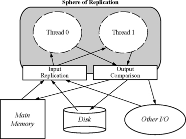
FIGURE 8.3 Sphere of replication of an RMT system. The sphere of replication includes the two thread contexts running redundant code.
Unlike hardware RMT systems that typically use separate hardware contexts, such as registers, address space, and separate program counters, for each of the redundant threads, a software RMT instantiation can implement the redundant versions within the same hardware context. Then the redundant versions would share the same control-flow mechanism, such as the program counter. Consequently, in a software RMT implementation, any control-flow change, such as a branch to a new instruction, must be checked for faults to avoid reducing the fault coverage. In terms of the sphere of replication, hardware RMT systems have the program counter inside the sphere, whereas in software RMT implementations the program counter is typically outside the sphere.
The performance degradation from software RMT systems is typically greater than that from hardware RMT systems. This is because the output comparison must be invoked fairly frequently. Since such output comparison is done in software, it slows down the program more than a hardware RMT system would.
This section discusses three implementations of software RMT: error detection by duplicated instructions (EDDI), software-implemented fault tolerance (SWIFT), and Spot. EDDI proposed by Oh et al. [9] implements software RMT on a MIPS instruction set using a compiler. SWIFT proposed by Reis et al. [11] also implements software RMT using a compiler, but for the Itanium architecture. It improves upon EDDI by excluding memory from the sphere of replication and by providing better protection on control transfers. Finally, Spot proposed by Reis et al. [13] implements software RMT using binary translation on an x86 architecture. Unlike EDDI or SWIFT, Spot does not require source code since it operates directly on the binary. None of these software systems, to the best of my knowledge, is used commercially.
8.3.1 Error Detection by Duplicated Instructions
EDDI implements software RMT within a single hardware context [9]. It duplicates instructions within a single thread to create two redundant execution streams. To check for faults, it introduces compare instructions at specific points in a program. The existing architectural register file and memory address space are split in half between the two redundantly executing streams of computation. Consequently, both the register file and the memory are within the sphere of replication. This model will work for cache-coherent, shared-memory multiprocessors as well if the entire shared address space is split among the redundantly executing streams. In this model, I/O resides outside the sphere of replication, so special support may be needed to replicate I/O operations (e.g., DMA from an I/O device to memory). The same issue will arise for interrupts and other forms of asynchronous exceptions.
EDDI Transformation
Figure 8.4 shows an example transformation that the EDDI scheme will perform. Registers R11, R12, R13, and R14 are registers used in the first executing stream, whereas R21, R22, R23, and R24 are the corresponding registers used in the second executing stream. The original program segment shown in Figure 8.4a consists of a load, an add, and a store instruction. Figure 8.4b shows the EDDI transformation. Each instruction is redundantly executed. However, EDDI only checks inputs to the store—registers R11 and R14—for faults. In EDDI, there is a slight subtlety in memory address comparison. Since memory is split into two halves, the corresponding memory addresses in the two redundant versions are not the same. Nevertheless, they could be made to be at a fixed offset from one another. The compare instruction must take this into account. For simplicity, this effect is not shown in Figure 8.4. Also, because the sphere of replication includes main memory, EDDI could have relaxed this constraint and checked only I/O operations through system calls.
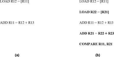
EDDI also checks inputs to branch instructions in the same way it checks inputs to store instructions. This guarantees that EDDI has correct inputs to a branch instruction. Nevertheless, the branch instruction could receive incorrect inputs due to a particle strike on the datapath from the register to the branch instruction’s execution unit.
EDDI Evaluation
To evaluate the effectiveness of EDDI, Oh et al. [9] performed random bit flips in the code segment to see how many of these bit flips result in an error. This methodology neither reflects the true soft error characteristics of a processor or a machine nor allows computing the AVF. Nevertheless, the methodology gives an idea of how many bit flips injected in a code stream may result in an error. Using this methodology, Oh et al. [9] show that the percentage of undetected incorrect output for eight benchmarks—FFT, Hanoi, Compress, Qsort, Fibonacci, Insert-sort, Matrix multiply, and Shuffle—reduce from 20% to 1.5% on average.
Figure 8.5 shows the performance degradation from introducing extra instructions in the code stream. On a two-way superscalar machine, which in a cycle can execute a maximum of two instructions from either of the two executing streams, the average performance degradation ranges between 36% and 111%. The degradation is not uniformly 100% because in many cases a processor may not be able to issue a maximum of two IPCs from a single execution stream because of interinstruction dependences. In such a case, the redundant instructions can execute in parallel, thereby causing less performance degradation. This parallel execution effect is more pronounced in a four-way issue processor pipeline where the performance degradation ranges from 13.3% to 105.9%.

FIGURE 8.5 EDDI execution time overhead in MIPS R4400 (two-way issue) and R10000 (four-way issue) processors. Reprinted with permission from Oh et al. [9]. Copyright © 2002 IEEE.
8.3.2 Software-Implemented Fault Tolerance
In many ways SWIFT is similar to EDDI. SWIFT implements software RMT for an Itanium2 architecture using a single hardware context [11]. Like EDDI, SWIFT splits the registers among the two redundant versions, thereby including the register file in the sphere of replication. Unlike EDDI, however, SWIFT does not duplicate memory since it checks every store for faults, and memory is typically protected with ECC. By placing memory outside the sphere of replication, SWIFT achieves two benefits. First, it reduces system cost. Second, it makes it easier to do input replication for I/O operations. For example, DMA operations can simply transfer I/O data directly to the single copy of memory, thereby making it unnecessary to change how I/O devices or the OS operates.
SWIFT still duplicates the load instruction to ensure that both redundant execution streams have the correct inputs from load instructions. This may cause false DUE since the second redundant load may pick up a different, yet correct, value. This can happen if an I/O device or another processor in a shared-memory multiprocessor changes the loaded value between the two corresponding load operations.
SWIFT provides better control-flow checking than EDDI using an extension of the basic idea of SIS (Fault Detection Using SIS, p. 299). Recall that control-flow changes in a software RMT implementation using a single context may need to be protected since the control-flow mechanism is outside the sphere of replication unlike a hardware RMT implementation. There are two kinds of checks the software must perform. First, one must ensure that the registers used by the control transfer instructions have the correct values. Second, one must ensure that the transfer itself happened correctly. Ensuring the first condition implies checking the register values feeding the control instructions. Both EDDI and SWIFT do this check.
SWIFT uses signatures of predicted hyperblocks, which are extensions of basic blocks, to ensure that the control transfer happens correctly. The mechanism reserves a designated general-purpose register—referred to as the GSR—to hold the signature for the currently executing basic block. These signatures are generated for basic blocks in a manner similar to that for SIS. Before the control transfer happens, the basic block asserts its target using a second register called RTS. After the control transfer takes place, the target decodes its signatures from RTS and compares it to the statically assigned signature of the block it is supposed to be in.
Specifically, let us assume that SIG_CURRENT is the signature of the current basic block. Let us also assume that SIG_TARGET is the signature of the basic block that the control should be transferred to. Before the control transfer in the current basic block, SWIFT would execute the following operation: RTS = SIG_CURRENT XOR SIG_TARGET. Once the branch is taken, the instruction GSR = GSR XOR RTS is executed. It should be noted that GSR contains SIG_CURRENT before this XOR operation is executed. If the control transfer happens correctly, GSR would become SIG_TARGET through this operation (since A XOR A XOR B = B). However, if the control transfer happens incorrectly, then the GSR value will not match the signature of the basic block the control was transferred to. Thus, when SWIFT compares GSR (after the XOR operation) with the statically generated signature for the basic block, it can immediately find the fault.
SWIFT’s performance and AVF reduction capability are described later in this chapter in the section CRAFT: A Hybrid RMT Implementation, p. 310.
8.3.3 Configurable Transient Fault Detection via Dynamic Binary Translation
In a software implementation, it is often easier to trade off reliability for performance because the software can be changed or adopted to specific needs. Reis et al. [13] used this observation to implement a software RMT scheme called Spot in which they could adjust the level of reliability required by a user. Spot uses the general principles of SWIFT—as described in the previous subsection—but implements software RMT using binary translation for an x86 architecture. Subsequently, the binary translation mechanism, an evaluation of Spot, and how Spot can be used to modulate the level of reliability a user may want are described.
Fault Detection via Binary Translation
Spot implements software RMT using the Pin dynamic instrumentation framework [4]. Pin allows users to insert code snippets into an existing binary. The code snippets for Spot are the reliability transformations to introduce redundant and check instructions. Introducing new code snippets in an existing binary can be challenging. For example, the new binary must change any branch address affected by the introduction of new code.
It is also difficult to statically handle many other challenging issues, such as variable-length instructions, mixed code and data, statically unknown indirect jump targets, dynamically generated code, and dynamically loaded library. Hence, Pin uses a dynamic instrumentation framework in which Pin combines the original binary and new code snippets dynamically at run-time. To reduce the cost of binary translation, Pin uses a software code cache that stores the most recently executed transformed code. Unlike SWIFT, Spot does not do signature checking because it does not have the program’s CFG. Instead, it checks the source registers feeding a branch.
Evaluation
Unlike EDDI or SWIFT, Spot computes the AVF of the architectural register file to guide reliability modulation (the reader is referred to Chapter 3 and Chapter 4 for AVF analysis techniques). Current processors do not provide hardware hooks to allow a program to estimate its AVF at run-time, but researchers are exploring the area [16]. Consequently, it is difficult to compute the AVF at run-time as the program executes. Instead, Reis et al. [13] do SFI into the architectural register file as a program runs (see Computing AVFs Using SFI into an RTL Model, p. 146, Chapter 4). The fault is injected into a random bit at a random point in time as the program executes.
If the program runs to completion, then the fault was masked and the corresponding bit into which the fault was injected was un-ACE (unnecessary for ACE). If the program produces the wrong output, if the program does not run to completion, or if the program’s exit code indicates an error, then the corresponding bit for that fault injection is classified as ACE. Then dividing the total number of ACE instances by the total number of injected faults gives the average SDC AVF of the register file. Similarly, the DUE AVF is computed as the ratio of ACE and un-ACE instances detected by Spot and the total number of injected faults.
This fault injection study with 15 SPEC benchmarks shows that the SDC AVF for the register file reduces from 20.2% to 6.5%, resulting in three-fold increase in SDC coverage. The difference—20.2% – 6.5%–13.7% is the true DUE AVF. The actual DUE AVF goes up slightly more because of false DUE effects (in which faults in un-ACE bits are flagged as errors).
Figure 8.6 shows the performance degradation experienced by SPEC integer benchmarks when Spot implements the highest level of reliability it can offer. On average, Spots slow down execution four-fold. In the figure, duplication is the overhead from duplicating the instruction streams to create the redundant execution streams, whereas detection shows the overhead for instructions to check for errors. Basepin is Pin’s overhead to implement the dynamic binary translation. As is obvious from the figure, both detection and duplication add significant overhead to Spot’s implementation. Spot’s high-performance degradation may be tolerable when a system cannot complete a program because of frequent soft errors. If Spot can be combined with an error recovery mechanism (discussed later in this chapter), then it can let a program proceed to completion. Spot’s performance degradation can, however, be reduced if the system requires reduced levels of reliability. The next subsection discusses how to trade off reliability for performance.

FIGURE 8.6 Execution time increase from Spot’s software RMT implementation using the dynamic binary translator Pin. Reprinted with permission from Reis et al. [13]. Copyright © 2006 IEEE.
Trading off Reliability for Performance
One way to reduce the performance overhead from Spot’s software RMT implementation is to incur greater numbers of SDC errors. To do this effectively, one can protect structures with higher AVF or bit counts and potentially remove the protection on structures with lower AVFs. For example, in an x86 architecture, the registers EBP and ESP are typically highly susceptible to transient faults. These registers are used primarily as pointers loading from and storing to memory. Hence, faults in these registers will likely cause a segmentation fault.
Spot allows each architectural register to be either protected or not protected via the binary translation mechanism. If a register is unprotected, instructions to duplicate the operation that uses the register and instructions that detect a fault in that register are both eliminated, thereby improving performance of the application. Given that the x86 architecture has eight registers, one can create 28 or 256 combinations. For example, one of the 256 combinations could have protection on the registers EBP and ESP but no protection on the other six registers.
Figure 8.7 shows the performance of each of the 256 combinations against their SDC AVF. The left side of the graph contains data points that have EBP protected, causing greater execution time, and the right side of the graph typically has no protection for EBP. As this graph shows, there is performance-reliability trade-off that software can exploit. For example, a user may choose to get a twofold degradation in performance for an SDC AVF of 15% (point B in Figure 8.7), instead of a four-fold degradation in performance with an SDC AVF of 5% (point A in Figure 8.7).
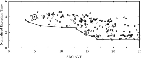
FIGURE 8.7 Trading off performance for reliability for the SPEC integer benchmark gap. Points A and B are discussed in the text. Reprinted with permission from Reis et al. [13] Copyright © 2006 IEEE.
Computing AVFs to make this trade-off can, however, be challenging. Obtaining the AVFs for architectural register files requires numerous fault injection experiments on a per-application basis, which can be tedious. A programmer typically has visibility into architectural structures only. Microarchitectural structures are not exposed to the programmer, and current hardware does not provide any way to compute what the AVFs of different structures could be. To make matters more complex, AVFs change across structures, so minimizing the AVF of a register file alone may not mean that the SDC rate of a processor running an application has been lowered. This remains a future research area in computer architecture.
8.4 Fault Detection Using Hybrid RMT
Software fault detection schemes typically have two limitations. First, the extra duplication and/or checks add overhead and degrade performance. Both SIS and software RMT incur significant performance degradation.
Second, software often does not have visibility into certain structures in the hardware and therefore is often unable to protect such structures. For example, a software RMT implementation compares input operands for stores. Then the store can be executed. At this point, the store retires and sends its data to the memory system. Usually, in a modern dynamically scheduled processor, a store resides in a store buffer. Once the store retires, it is eventually evicted from the store buffer, and its data are committed to the memory system. A software RMT implementation that creates the redundant contexts within the same hardware thread cannot, however, protect the datapath from the store buffer to the memory system because it does not have visibility into this part of the machine.
Hence, researchers have examined hybrid RMT schemes that combine the best of software and hardware RMT schemes. Software RMT schemes are typically cheaper to implement since they do not need extra silicon area. Hardware RMT schemes provide better fault coverage and lower performance degradation. Compiler-assisted fault tolerance (CRAFT) is one such hybrid RMT scheme, which is described in this section.
8.4.1 CRAFT: A Hybrid RMT Implementation
CRAFT augments SWIFT’s implementation of software RMT with hardware support that improves both fault coverage and performance [12]. CRAFT introduces two changes in hardware: one for store checks and one for load value replication (Table 8.1). As shown in Table 8.1, with no fault detection, the stores and loads execute as is. SWIFT inserts extra instructions to duplicate the instruction stream and then compares the inputs to both store and load instructions to ensure that instructions receive the correct values. Once a value is loaded using the original instruction, SWIFT copies the loaded value to the redundant stream’s corresponding register.
TABLE 8-1
Comparison of CRAFT with Other Techniques. Rn = [Rm] Denotes a Load Operation That Loads Register Rn with a Value from Memory Location Rm. Similarly, [Rn] = Rm Denotes a Store Operation That Stores the Value in Register Rm to the Memory Location Rn

Although SWIFT ensures that the registers that are inputs to stores are fault free, it cannot protect the store instruction itself or the datapath from the registers to the branch. For example, if the store instruction is corrupted in the store buffer after the store receives its inputs, then SWIFT cannot detect the fault. Further, the extra check instructions themselves add overhead and degrade performance. To reduce this overhead, Reis et al. [12] propose to introduce new store instructions in the architecture and a corresponding checking store buffer (CSB) that will handle the store checks. This creates two flavors of store instructions: the original ones that cannot commit their data to memory and the duplicate ones that will commit their values to memory after the stores are checked for faults. CRAFT introduces both flavors of instructions—possibly back-to-back—as shown in Table 8.1. When both the original and duplicate stores enter the CSB, the CSB will compare their inputs to ensure that they are fault free and then commit the value of the original store. The CSB must be implemented carefully to ensure that both redundant streams can make forward progress. This can be usually solved by reserving a few CSB entries for each stream.
SWIFT is also partially vulnerable in its load check and duplication sequence (Table 8.1). The load instruction can still experience a transient fault between the address check (branch instruction shown in table) and the address consumption by the load instruction. Also, there is a vulnerability to transient faults between the original load (R11 = [R12]) and the move operation (R21 = R11). That is, if R11 is corrupted after the load operation, then R21 will receive the corrupted value, and both redundant streams will end up using the same faulty value, which will go undetected.
To avoid these problems associated with a load operation, CRAFT provides the option of using a hardware LVQ as described in Load Value Queue, p. 235, Chapter 6. The LVQ is a structure that allows the primary redundant stream to forward load values to the duplicate stream using a queue of load addresses and values. Unlike SWIFT, CRAFT will issue two load instructions: one is the original one and the other is the duplicate one. The duplicate one will pick up its load value from the LVQ instead of the cache. It should be noted that if both redundant loads read their values from the cache, then there is the possibility of a false error. This is because the value in the cache could be changed by an I/O device or another processor before the second redundant load has the opportunity to read it from the cache. SWIFT avoids this problem by only issuing one load and copying the loaded value to the redundant stream’s register. CRAFT not only avoids this using the LVQ but also provides greater fault coverage since the load path is now completely protected.
8.4.2 CRAFT Evaluation
Figure 8.8 shows a comparison of AVF from the different schemes. NOFT has no fault tolerance. SWIFT is described in the previous subsection. CRAFT has three versions: one with CSB, one with LVQ, and one with both the CSB and the LVQ. CRAFT:CSB uses SWIFT’s load replication scheme and CRAFT:LVQ uses SWIFT’s store checking scheme. SDC is broken into two pieces: dSDC is the one that definitely causes an incorrect output but without crashing the program. pSDC is a probable SDC that causes system hangs or other program crashes without producing an output. AVFSDC = AVFdSDC +AVFpSDC. (Total) AVF = AVFdSDC + AVFpSDC +AVFDUE.
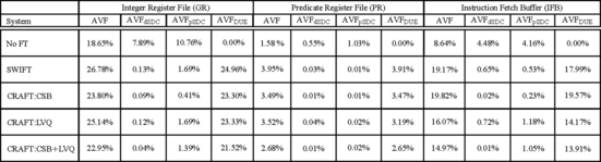
FIGURE 8.8 SDC and DUE AVF of three structures with different fault detection options. Reprinted with permission from Reis et al. [12]. Copyright © 2005 IEEE.
Both the performance and AVF were measured on a simulated Itanium2 processor using benchmarks drawn from SPEC CPUINT2000, SPEC CPUFP2000, SPEC CPUINT95, and MediaBench suites. To measure the AVF, the authors injected faults randomly into three structures—integer register file, predicate register file, and instruction fetch buffer–in a detailed timing simulator of the Itanium2 processor. Each faulty simulation was run until all effects of the fault manifested in an architectural state or until the fault was masked. Once all effects of a fault manifest in an architectural state, the authors only needed to run the functional (or architectural) simulation, thereby improving simulation speed and accuracy of AVF numbers by running programs to completion, which allowed the authors to precisely determine if the faulty bit was ACE or un-ACE.
As expected, SWIFT reduces the SDC AVF for the three structures 19-fold, which is a significant improvement. CRAFT:CSB decreases the AVF more than 2.5-fold over SWIFT. The introduction of the LVQ, however, makes CRAFT’s AVF worse because the loads in CRAFT:LVQ could experience a segmentation fault before the load address is checked. In contrast, SWIFT checks the fault before the load is executed in the program, thereby avoiding this problem. CRAFT could avoid this problem if a mechanism to delay raising the segmentation fault until the load addresses are compared for faults is provided (e.g., see Mechanism to Propagate Error Information, p. 197, Chapter 5).
Reis et al. [12] also introduced a new metric called MWTF to measure the profitability of the different fault detection schemes. MWTF is similar to the metric MITF, as discussed in Exposure Reduction via Pipeline Squash, p. 270, Chapter 7. MITF measures the average number of instructions committed between two errors. MITF, however, does not apply in this case because the number of instructions of each fault detection scheme is different from that of the original non-fault-detecting scheme. However, the total work done by each program under each fault detection scheme is still the same. Hence, MWTF is a more appropriate term. Like MITF, MWTF is proportional to the ratio of performance and AVF. Performance is expressed as the inverse of execution time. Thus, a scheme could be better than another one if its overall MWTF is higher than that of the other.
Figure 8.9 shows the MWTF for SDC and dSDC errors for the four fault detection schemes. As expected, CRAFT:CSB has the highest MWTF and is the most profitable scheme. CRAFT with LVQ loses out because of the increased AVF experienced due to the faulting loads. However, if only dSDCs—that is, SDC errors that always result in only an output mismatch with no other clue that a fault has occurred—are considered, then CRAFT with LVQ schemes do better.

FIGURE 8.9 Normalized MWTF for three structures and the four fault detection techniques. GR = general purpose registers, PR = predicate registers, IFB = instruction fetch buffer. Reprinted with permission from Reis et al. [12]. Copyright © 2005 IEEE.
8.5 Fault Detection Using RVMs
This section examines the implementation of fault detection in the virtual machine layer (Figure 8.1). In the presence of a virtual machine software layer, application accesses to I/O devices and physical memory go through another level of indirection. Instead of accessing and managing the hardware resources directly, the OS implicitly calls the virtual machine layer software that is inserted between the hardware layer and the OS. The virtual machine layer—often referred to as the virtual machine monitor (VMM)–manages these accesses on behalf of the OS. Because the OS does not have direct access to the hardware devices, one can run multiple copies of the same OS or multiple OSs on a single VMM.
In recent years, VMMs have become increasingly popular because of two reasons. First, they provide fault isolation. In some OSs, such as Microsoft Windows, an application crash or a device driver error may bring down the entire OS. With an underlying VMM, such a crash would only bring down the offending virtual machine but not the entire system. Second, in many data centers, machines are underutilized because they often run dedicated applications, such as a file server, an e-mail server. The availability of spare compute power and virtual machine software allows data center managers to consolidate multiple server software—each running on its private copy of the OS—on a single physical machine.
Popular VMMs, also sometimes called hypervisors, include VMWare’s ESX server, Microsoft’s Viridian server, and the freely available Xen software. Many companies, such as Marathon Technologies, have built their own private virtual machine layer to implement fault tolerance. Certain virtual machines, such as Xeon, require special OS support to run efficiently and therefore cannot run unmodified commodity OSs. This style of virtualization is known as paravirtualization.
Implementing fault detection using a pair of RVMs uses the same principles as RMT described in Chapter 6. The sphere of replication includes the two RVMs running identical copies of applications and OSs (Figure 8.10). The output comparison is done at I/O requests from the application and OS to the VMM. The VMM synchronizes both copies of the virtual machine and sends the I/O request out to the I/O devices. To provide storage redundancy, the same I/O request could be sent to multiple identical disks as well.

Input replication can be tricky since both redundant copies must receive I/O interrupts and responses at the same exact instruction. To facilitate input replication, execution is typically broken up into multiple epochs. An epoch can be a sequence of a preset number of committed instructions. At the end of an epoch, I/O interrupts are replicated and delivered to the RVMundant virtual machines, so that both virtual machines process them at the same instruction boundary.
Like other software fault detection schemes, reads and writes from special machine registers, such as the cycle counter register or time of day register, must be handled with care since the RVMs can read them at different times. Such registers can be treated as being outside the sphere of replication. Writes to such registers must be synchronized and compared by the VMM. Reads from these registers can specify an epoch boundary. The VMM can replicate these reads to the RVMs.
The commercially available Marathon EverRun server uses similar principles of RVMs to implement fault detection completely in software [15]. The EverRun machine also allows recovery in case one of the virtual machines hangs. The Ever-Run machine accomplishes this by copying the state of one virtual machine to another and then transparently restarting the entire EverRun server. Bressoud and Schneider [1] created a similar fault detection scheme using RVMs.
8.6 Application-Level Recovery
Software fault detection techniques discussed so far can reduce the SDC component of the SER and often replace it with DUE. Once a fault is detected, an error recovery scheme needs to be triggered if the system wants to reduce its DUE rate. Error recovery can be implemented either in hardware or in software. Chapter 7 discussed various hardware error recovery schemes. The rest of this chapter discusses software error recovery mechanisms.
Software error recovery schemes, like software fault detection schemes, can be implemented in three places: in the application, in the OS, or in the VMM. Application-level recovery allows an application programmer to implement recovery without changing the underlying OS. Database applications have traditionally implemented their own recovery schemes to “undo” failed transactions. OS-level recovery requires changing the OS itself (or at least some device drivers), which can be more difficult to implement, test, and deploy. A virtual machine can run several commodity OSs simultaneously and can be a convenient spot to implement both fault detection and software error recovery since it does not require any change to the OSs themselves.
This section discusses three flavors of application-level error recovery: forward error recovery using triplication and arithmetic codes, log-based backward error recovery in a database system using logs, and a checkpoint-based backward error recovery scheme for shared-memory parallel programs. Applications themselves can, of course, implement their own recovery scheme using application-specific knowledge and custom implementations. A complete coverage of all such techniques is beyond the scope of this book. Nevertheless, the three schemes described in this section will illustrate some of the challenges faced by application-level recovery schemes. The basic principles of error recovery, such as output and input commit problems, are similar to what has been discussed for hardware implementations of backward error recovery in Chapter 7.
8.6.1 Forward Error Recovery Using Software RMT and AN Codes for Fault Detection
As the name suggests, a forward error recovery scheme continues to execute–that is, move forward–on encountering an error. In an application, such a forward recovery can be implemented by using three redundant elements: the first two for fault detection and the third for recovery. One possibility is to implement three redundant streams of instructions and use majority voting to decide what stream is in error. Alternatively, one can use two redundant streams augmented with an additional fault detection capability to decide the copy in error. These schemes are described by Reis et al. [10].
The first scheme of Reis et al.—called SWIFT-R—intertwines three copies of a program and adds majority voting before critical instructions (Figure 8.11). Figure 8.11 shows an example of how this can be implemented. Registers R1n denote the original set of registers, registers R2n denote the second set, and registers R3n denote the third set of registers. As Figure 8.11 shows, before a load (R13 = [R14]), majority voting ensures that one has the correct value in R14. The add instruction is triplicated. Finally, before a store operation is performed ([R11] = R12), both its operands are validated through majority voting. On average, Reis et al. found that SWIFT-R degrades performance by about 200% using this triplication mechanism. However, it improves the SDC AVF of the architecture register file about 10-fold.

To reduce the performance degradation from triplicating every instruction, Reis et al. also explored the idea of using only two redundant streams. To facilitate the recovery, the second stream is encoded as an AN code (see AN Codes, p. 182, Chapter 5), where A= 3 is a constant that multiplies the basic operand N found in the first redundant stream. Errors in the AN-coded stream can be detected by dividing the operands in this stream by A. If the modulus is nonzero, then this stream had an error. Alternatively, if operands in the first non-AN-coded stream when multiplied by A do not match with the AN-coded stream, but the AN operand is divisible by A, then the first stream must be in error. Once the error is decoded, the state of the correct stream can be copied to the faulty stream and execution restarted. This AN-coding mechanism significantly improves the performance over SWIFT-R and degrades the performance on average by only 36%. However, this AN-coding mechanism reduces the SDC AVF of the architectural register file by only around 50%. This AN-coding scheme has lower fault coverage than SWIFT-R because AN-coded values cannot propagate through logical operations, such as OR and AND. Also, multiplying an operand N by A may cause an overflow. In cases where the compiler cannot guarantee an overflow, it cannot fully protect the operands.
8.6.2 Log-Based Backward Error Recovery in Database Systems
Unlike the somewhat generic forward error recovery technique described in the previous section, the error recovery technique in this section is customized to a database program. A database is an application that stores information or data in a systematic way. It allows queries that can search, sort, read, write, update, or perform other operations on the data stored in the database. Databases form a very important class of application across the globe today and are used by almost every major corporation. Companies store information, such as payroll, finances, employee information, in such databases. Consequently, databases often become mission-critical applications for many corporations.
To avoid data loss, databases have traditionally used their own error recovery schemes. Many companies, such as Hewlett-Packard’s Tandem division, sold fault-tolerant computers with their own custom databases to enhance the level of reliability seen by a customer. Databases can get corrupted due to both a hardware fault and a software malfunction. The error recovery schemes for databases are constructed in such a way that they can withstand failures in almost any part of the computer system, including disks. This includes recovering from transient faults in processor chips, chipsets, disk controllers, or any other silicon in the system itself.
To guard against data corruption, commercially available commodity databases typically implement their own error recovery scheme in software through the use of a “log.” Database logs typically contain the history of all online sessions, tables, and contexts used in the database. These are captured as a sequence of log records that can be used to restart the database from a consistent state and recreate the appropriate state the database should be in. The log is typically duplicated to protect it against faults.
The rest of this subsection briefly describes how a database log is structured and managed. For more details on databases and database logs, readers are referred to Gray and Reuter’s book on transaction processing [3]. There are three key components to consider for a log: sequential files that implement the log, the log anchor, and the log manager. Logs are analogous to hardware implementations of history buffers (see Incremental Checkpointing Using a History Buffer, p. 278, Chapter 7), but the differences between the two are interesting to note.
Log Files
A log consists of multiple sequential files that contain log records (Figure 8.12). Each log file is usually duplexed—possibly on different disks–to avoid a single point of failure. The most recent sequential files that contain the log are kept online. The rest are moved to archival storage. Duplicate copies of each physical file in a log are allocated at a time. As the log starts to fill up, two more physical files are allocated to continue the log. Because the log consists of several duplicated files, its name space must be managed with care.

Log Anchor
The log anchor encapsulates the name space of the log files. The redundant log files use standard file names ending with specific patterns, such as LOGA00000000 and LOGB00000000, which allow easy generation and tracking of the file names. The log anchor contains the prefixes of these filenames (e.g., LOGA and LOGB) and the index of the current log file (to indicate the sequence number of the log file among the successive log files that are created).
The log anchor typically has other fields, such as log sequence number (LSN), for various log records and a log lock. The LSN is the unique index of a log record in the log. The LSN usually consists of a record’s file number and relative byte offset of the record within that file. An LSN can be cast as an integer that increases monotonically. The monotonicity property of a log is important to ensure that the log preserves the relative timeline of the records as they are created. The log anchor typically maintains the LSN of the most recently written record, LSN of the next record, etc.
The log anchor also controls concurrent accesses to the end of the log using an exclusive semaphore called the log lock. Updates to sequential files happen at the end of the file. Hence, accesses to the end of the log by multiple processes must be controlled with a lock or a semaphore (or a similar synchronization mechanism). Fortunately, updates happen only to the end of the log since intermediate records are never updated once they are written. Access to this log lock could become a performance bottleneck. Hence, the log lock must be implemented carefully.
Log Manager
The log manager is a process or a demon that manages the log file and provides access to the log anchors and log records. In the absence of any error, the log manager simply writes log records. However, when an application, a system, or a database transaction reports an error, the log is used to clean up the state. To return each logged object to its most recent consistent state, a database transaction manager process would typically read the log records via the log manager, “undo” the effect of any fault by traversing backward in time, and then “redo” the operations to bring the database back to its most recent consistent state.
8.6.3 Checkpoint-Based Backward Error Recovery for Shared-Memory Programs
Checkpoint-based error recovery is another backward error recovery scheme. Unlike log-based backward error recovery, checkpoint-based schemes must periodically save their state in a checkpoint; hence, the application’s performance may suffer if checkpoints are taken frequently. A log-based recovery updates the log incrementally, so it incurs relatively lower performance degradation for the application compared to checkpointing. However, in the log-based error recovery, to create the consistent state of the application, one must traverse the log and recreate the application’s state incrementally. Hence, the error recovery itself is slower in log-based backward error recovery than in checkpoint-based recovery, which can simply copy the checkpoint to the application’s state and continue execution.
This section discusses an example of application-level checkpointing proposed by Bronevetsky et al. [2]. Although the discussion will be centered around shared-memory programs, the same basic principles can be applied to message-passing parallel programs as well. First, a brief overview of the technique is given. Then, two important components of the program, saving state and avoiding deadlocks for synchronization primitives, are discussed.
Overview
In the method of Bronevetsky et al., an executable with checkpointing capabilities must be created. To achieve this, an application programmer must annotate a shared-memory parallel program with potentialCheckpoint() calls in places where it may be safe to take a checkpoint (not shown in figure). The authors’ preprocessor then instruments the original application source code with code necessary to do the checkpointing. The preprocessor avoids taking checkpoints at some of the potentialCheckpoint() calls where it deems it unnecessary. Then the code runs through the normal compilation procedure and creates the corresponding executable.
When this executable is run, there is a coordination layer to ensure that system-wide checkpoints are taken at the correct point without introducing deadlocks (Figure 8.13). The running program makes calls to the OpenMP library that implements the shared-memory primitives. OpenMP is a current standard to write shared-memory parallel programs. These shared-memory primitives in turn run on native shared-memory hardware.

FIGURE 8.13 Overview of compile- and run-time methodologies used in checkpoint-based backward error recovery proposed by Bronevetsky et al.
The checkpointing protocol itself is done in three steps. (1) Each thread calls a barrier. (2) Each thread saves its private state. Thread 0 also saves the shared state. (3) Each thread calls a second barrier. The recovery algorithm works in three phases as well. (1) Every thread calls a barrier. (2) All threads restore their private variables. Thread 0 restores the shared variables as well. (3) Every thread calls a barrier. Execution can restart after step 3.
A barrier operation—both for checkpointing and for normal operations–must ensure that all threads globally commit their memory values, so that all threads have the same consistent view of memory after emerging from the barrier. The checkpoint barriers must also not interfere with normal barriers in a shared-memory program. This is because one of the threads could enter a checkpointing barrier—waiting for other threads to do the same–whereas another thread could enter a normal program barrier–waiting for other threads to do the same. This would cause a deadlock. How to avoid such situations is discussed below.
Saving State
Hardware typically does not have visibility into an application’s data structures and hence must interpret the entire register file or the memory as an architectural state. In contrast, an application can precisely identify what constitutes its state, which typically consists of the global variables, the local variables, the dynamically allocated data called the heap, and a stack of function calls and returns. An application’s checkpoint must consist of these data structures.
The global and local variables are easily identifiable in an application and can be saved at checkpoint time. To tackle the heap, Bronevetsky et al. [2] created their own heap library to keep track of any dynamically allocated data structures, so that at checkpoint time, the application can easily identify how much of the heap has been allocated and must be saved. Instead of keeping track of the stack by using implementation-dependent hardware registers, the authors use their own implementation of the call stack. For every function call that can lead to the potentialCheckpoint() call, they push the function call name into a separate pc_stack. For every function return, they pop the stack. This allowed the authors to precisely keep track of the stack. Variables local to a function call are similarly saved in a separated local variable stack corresponding to every function call push.
Avoiding Deadlocks in Synchronization Constructs
Shared-memory parallel programs usually offer two synchronization primitives—barrier and locks—both of which can cause deadlocks during checkpoint creation. A barrier is a global synchronization primitive. All threads must reach the barrier and usually commit any outstanding memory operation before any thread can exit the barrier. A lock and unlock pair is typically used by a single thread to create a critical section in which the thread can have exclusive access to specific data structures guarded by the lock. When a thread holds a lock, other threads requesting the lock must wait until the thread holding the lock releases it through an unlock operation. Message-passing programs do not have barriers or locks, so deadlocks associated with locks and barriers will not arise in message-passing programs.
Figure 8.14 shows examples of deadlock scenarios for a barrier and for a lock operation. A deadlock could occur if one of the threads (Thread 0 in Figure 8.14a) enters a checkpoint call site, whereas the other threads wait for a normal program barrier. Thread 0 will never enter the normal program barrier because it waits for Thread 1 and Thread 2 to also enter the global checkpoint creation phase. Thread 1 and Thread 2 wait for Thread 0 to enter the normal program barrier instead. This causes a deadlock.

FIGURE 8.14 Deadlock scenarios for barrier (a) and lock (b) operations when global checkpoints must be taken.
Similarly, Figure 8.14b shows a deadlock scenario with a lock operation. Thread 1 grabs a lock and enters its critical section. Then it decides to take a checkpoint and waits for Thread 0 to enter the checkpoint phase as well. Thread 0, on the other hand, tries to acquire the lock Thread 1 is holding, fails, and waits for Thread 1 to release the lock. Thread 1 will not release the lock till Thread 0 enters the global checkpoint phase. Thread 0 will not enter the global checkpoint phase, since it waits for Thread 1 to release the lock. This causes a deadlock.
The solutions to both deadlock problems are simple. For the barriers, Thread 1 and Thread 2 must be forced to take a checkpoint as soon as they hit a normal program barrier, and some other thread (Thread 0) in this case has initiated a checkpoint operation. This can be implemented through simple Boolean flags implemented via shared memory. Similarly, a flag can be associated with each lock. Before a thread initiates a checkpoint, it sets the flag corresponding to all locks it is holding to TRUE. Then it releases all its locks. When a different thread acquires the lock, it checks the value of the flag associated with the lock. If it is TRUE, then it releases the lock and takes a checkpoint. Eventually, the thread that originally held the lock and initiated the checkpoint re-requests the lock, acquires it, and continues with normal operation.
8.7 OS-Level and VMM-Level Recoveries
Recovery in the OS or the VMM is very appealing. One can imagine running multiple applications, such as an editor and a playing audio in the background, when one’s machine crashes. When the system recovers from this error, it would be very nice to have both the editing window with unsaved changes visible and the song replayed exactly from where it was left off. This requires extensive checkpointing and recovery mechanisms in either the OS or the VMM. Commercial systems are yet to fully adapt these techniques.
An interesting OS-level approach to handle the output commit problem has been proposed by Masubuchi et al. [6]. Disk output requests are redirected to a pseudo-device driver rather than to the device driver (Figure 8.15). The pseudo-device driver blocks outputs from any process until the next checkpoint. Nakano et al. [7] further optimized this proposal by observing that disk I/O and many network I/O operations are idempotent and can be replayed even if the output has already been committed once before. This is because disk I/O is naturally idempotent. Network I/O is not idempotent by itself, but TCP/IP network protocol allows sending and receiving of the same packet with the same sequence number multiple times. The receiver discards any redundant copies of the same packet.

8.8 Summary
Software fault-tolerance techniques are gaining popularity. Recently, Marathon Technologies introduced software fault tolerance in its EverRun servers. Software fault detection and error recovery schemes can be implemented in various layers, such as in an application, in an OS, and in a VMM. Faults can be detected in an application using SIS or software RMT. In SIS, a program precomputes signatures corresponding to a group of instructions at compile time. By comparing these signatures to the ones generated at run-time, one can detect if the program flow executed correctly.
In contrast, software RMT runs two redundant versions of the same program through a single hardware context. Unlike hardware RMT implementations where the program counter is inside the sphere of replication, software RMT implementations share the same program counter among the redundant versions. Hence, the program counter is outside the sphere of replication and must be protected to guarantee appropriate fault coverage. Such software RMT schemes can be implemented either via a compiler or via binary translation. Software RMT schemes can also be augmented with specific hardware support, such as an LVQ or a CSB, to reduce the performance degradation incurred by a software RMT implementation. Similarly, faults can also be detected by running a pair of RVMs that check each other via the VMM.
Like hardware error recovery, software error recovery schemes can also be grouped into forward and backward error recovery schemes. In a software forward error recovery scheme, one can maintain three redundant versions of a program in a single hardware context. Alternatively, one can maintain two redundant versions but add software checks, such as AN codes, to detect faults in individual versions. On detecting a fault, the software copies the state of the faulty version to the correction version and resumes execution.
Software backward error recovery, like hardware schemes, can be based either on logs or on checkpoints. Log-based backward error recovery schemes, typically implemented in databases, maintain a log of transactions that are rolled back when a fault is detected. In contrast, a software checkpointing scheme periodically saves the state of an application or a system to which the application or the system can roll back on detecting a fault. Such recovery schemes can be implemented in an application, an OS, or a VMM.
References
Bressoud T.C., Schneider F.B. Hypervisor-Based Fault Tolerance. ACM Transactions on Computer Systems. February 1996;Vol. 14(No. 1):80–107.
Bronevetsky G., Marques D., Pingali K., Szwed P., Schulz M. Application-Level Checkpointing for Shared Memory Programs. 11th International Conference on Architectural Support for Programming Languages and Operating Systems (ASPLOS). October 2004:235–247.
Gray J., Reuter A. Transaction Processing: Concepts and Techniques. Morgan Kaufmann Publishers, 1993.
Luk C.-K., Cohn R., Muth R., Patil H., Klauser A., Lowney G., Wallace S., Reddi V.J., Hazelwood K. Pin: Building Customized Program Analysis Tools with Dynamic Instrumentation. ACM SIGPLAN Conference on Programming Language Design and Implementation. June 2005:190–200.
Mahmood A., McCluskey E.J. Concurrent Error Detection Using Watchdog Processors- A Survey. IEEE Transactions on Computers. February 1988;Vol. 37(No. 2):160–174.
Masubuchi Y., Hoshina S., Shimada T., Hirayama H., Kato N. Fault Recovery Mechanism for Multiprocessor Servers. 27th International Symposium on Fault-Tolerant Computing. 1997:184–193.
Nakano J., Montesinos P., Gharachorloo K., Torrellas J. ReViveI/O: Efficient Handling of I/O in Highly-Available Rollback-Recovery Servers. 12th International Symposium on High-Performance Computer Architecture (HPCA). 2006:200–211.
Nakka N., Kalbarczyk Z., Iyer R.K., Xu J. An Architectural Framework for Providing Reliability and Security Support. International Conference on Dependable Systems and Networks (DSN). 2004:585–594.
Oh N., Shirvani P.P., McCluskey E.J. Error Detection by Duplicated Instructions in SuperScalar Processors. IEEE Transactions on Reliability. March 2002;Vol. 51(No. 1):63–75.
Reis G.A., Chang J., August D.I. Automatic Instruction-Level Software-Only Recovery. IEEE Micro. January 2007;Vol. 27(No. 1):36–47.
Reis G.A., Chang J., Vachharajani N., Rangan R., August D.I. SWIFT: Software Implemented Fault Tolerance. 3rd International Symposium on Code Generation and Optimization (CGO). March 2005:243–254.
Reis G.A., Chang J., Vachharajani N., Rangan R., August D.I., Mukherjee S.S. Design and Evaluation of Hybrid Fault-Detection Systems. 32nd International Symposium on Computer Architecture (ISCA). June 2005:148–159.
Reis G.A., Chang J., August D.I., Cohn R., Mukherjee S.S. Configurable Transient Fault Detection via Dynamic Binary Translation. 2nd Workshop on Architectural Reliability (WAR). December 2006.
Schuette M.A., Shen J.P. Processor Control Flow Monitoring Using Signatured Instruction Streams. IEEE Transactions on Computers. March 1987;Vol. C-36(No. 3):264–276.
Tremblay G., Leveille P., McCollum J., Pratt M.J., Bissett T. Fault Resilient/Fault Tolerant Computing. European Patent Application Number 04254117.7. July 9th, 2004. filed
Walcott K.R., Humphreys G., Gurumurthi S. Dynamic Prediction of Architectural Vulnerability from Microarchitectural State. International Symposium on Computer Architecture (ISCA). June 2007:516–527. San Diego, California