
Introduction
Tingzhen Ming1,2, Wei Liu2, Yongjia Wu2, Jinle Gui2, Keyuan Peng2 and Tao Pan2, 1School of Civil Engineering and Architecture, Wuhan University of Technology, Wuhan, P.R. China, 2School of Energy and Power Engineering, Huazhong University of Science and Technology, Wuhan, P.R. China
Abstract
A brief introduction of the energy status quo is presented, followed by the existing solar thermal power plant technologies. The solar chimney power plant (SCPP) technology is presented. Later, a comprehensive introduction on the research and development of SCPP system is presented.
Keywords
Solar energy; solar chimney power plant system (SCPPS); chimney; turbine; collector; energy storage layer
1.1 Energy Background
1.1.1 The Energy Issue and the Status Quo
Energy is the lifeblood of the national economy and closely related to the living environments of human beings. Since the global energy crisis occurred in the 1970s, the depletion of fossil energy resources has caused economic recession in many developed countries, which affects the sustainable development of the national economy and social stability directly. The main cause of the wars and terrorist threats all around the world in recent decades should be attributed to the exploitative ways the developed countries adopted in controlling fossil energy resources. There is no doubt that, the overexploitation of fossil fuels has caused worldwide environmental pollution, global warming, melting glaciers in the Arctic region, human diseases increasing, and deterioration in the ecological environment. While developed countries sustain a high standard of living quality and economic development rate by relying on an excessive use of fossil fuels, the developing countries with the vast majority of the population of the world still cannot afford the necessary cost of traditional energy resources. In addition, they are not able to compete with the developed countries in the fight for fossil energy resources. The people in these countries are still living in poverty, backwardness, and lacking electricity and clean water, which in turn leads to the population surge and aggravates poverty. The protection of the Earth’s ecological environment, the sustainable progress of civilization, and the stability of the international community mainly depend on government regulation and control around the world, the environment protection sense of the public, the saving and clean use of fossil energy resources, the generalization and application of renewable energy, the well-organized control on the population growth in developing countries, and so on.
Consumption and production for all fuels except nuclear power have increased remarkably during the recent decades. For each of the fossil fuels, global consumption rose more rapidly than production. Table 1.1 shows the oil production and consumptions of the top 10 world countries in 2013 [1]. It indicates that the United States and China utilize a very large percentage of the world’s oil consumption.
Table 1.1
Oil Production and Consumption in 2013 (Millions of Barrels Per Day) [1]
| Rankings | Countries | Production | Countries | Consumption |
| 1 | United States | 12.343 | United States | 18.961 |
| 2 | Saudi Arabia | 11.702 | China | 10.303 |
| 3 | Russia | 10.764 | Japan | 4.531 |
| 4 | China | 4.501 | Russia | 3.515 |
| 5 | Canada | 4.073 | India | 3.509 |
| 6 | United Arab Emirates | 3.441 | Brazil | 2.998 |
| 7 | Iran | 3.192 | Saudi Arabia | 2.968 |
| 8 | Iraq | 3.058 | Canada | 2.431 |
| 9 | Kuwait | 2.812 | Germany | 2.403 |
| 10 | Brazil | 2.694 | South Korea | 2.324 |

Due to the increased consumption of fossil energy, the global CO2 emissions have grown significantly, with China and the United States ranking No. 1 and 2 since 2009 [2]. According to the Department of Energy’s (DOE) Energy Information Administration’s (EIA) forecasts for emissions from energy use until 2030 (Fig. 1.1), this trend will last if we do not intervene.

China has become one of the largest countries in energy production and consumption. The huge total reserves but relatively low per capita possession, uneven distribution, and low utilization efficiency are four key features of energy production and consumption in China. The total energy production in China is only less than the United States and Russia, ranking No. 3 in the world. The necessary energy use accounts for 10% of the world, ranking only second to the United States. The annual average economic growth rate for China was 9.7% while the growth rate of energy consumption was only 4.6% in the past 20 years. Since 1980, the total energy consumption for China has grown about 5% per year, which is nearly three times the world’s average growth rate. As China’s demand for energy keeps increasing, there is an enormous gap between China’s energy reserves and future development needs. The total amount of the energy gap was over 100 million tons of standard coal in 2003. It is predicted that the total energy gap will be about 250 million tons of standard coal in 2030, and it will reach about 460 million tons of standard coal in 2050. With the enlargement of the energy gap year by year, China’s dependence on energy imports will expand gradually, which is the primary concern for our energy security in the future. In addition, since China’s main energy source is coal, the conflict between economic development and environment pollution should be much more severe. Coal combustion produces a lot of CO2, SO2, NOx, and many other harmful gases, which are blamed for the greenhouse effect and acid rain. The emissions of trace elements and particulate matter in the coal combustion processes also threat human health.
The world’s energy reserve is not good news. Besides coal, oil, and natural gas reserves could be mined for less than 100 years. Despite the rapid development of nuclear power plant, uranium will be available for less than 100 years since the world’s uranium reserve is quite low. As for China, the recovery time will be only about 50 years. Furthermore, the general public have doubts on the nuclear fission technology and technology blockade. Some technical problems, such as protection from nuclear radiation, reactor control, and nuclear waste disposal [4–11], add to the uncertainty about the future of the technology. Thus, large-scale construction of nuclear power plants worldwide is not a permanent solution to the energy problem.
1.1.2 China’s Energy Policy and Prospect
In view of the energy, environmental, economic, and sustainable development problems, The Twelfth Five-Year Plan for the Economic and Social Development of the People’s Republic of China proposed energy construction policies of “implementing preferential taxation and investment, and mandatory market share policies to encourage the production and consumption of renewables and increase its proportion in primary energy consumption,” “Positively developing and utilizing solar, geothermal and ocean energy,” “Strengthening the exploitation and application of air water resources, solar, wind and other energies.” At the same time, the plan introduced the environmental protection policies of “the essential point of ecological protection transiting from post-treatment to protection in advance.” In addition, a hard target of a 4% energy saving during “Twelfth Five” is proposed. According to the development goals determined by The New and Renewable Energy Industry Development Plans and Key Points in 2000–2015, China’s new and renewable energy production would reach 43 million tons of standard coal by 2015, which is about 2% of the total energy consumption. China would cut more than 30 million tons of greenhouse gases emissions and more than 2 million tons of sulfur dioxide emissions. The visible effect would be indicated by a reduction in atmospheric pollution and an improvement of the atmospheric environment quality. Nearly 500 thousand jobs would be provided, and more than 5 million farmer families (more than 25 million people) living in remote areas would be alleviated from the lack of water and electric. So, exploitation and utilization of renewable energy is a strategic direction for China’s energy development. In recent years, the exploitation and use of new and renewable energies has developed rapidly throughout the world, with technologies being matured gradually, and economically viable products and equipment being put on the market quickly. It is expected that the development and utilization of the new and renewable technologies and market share of these technologies will breakthrough dramatically in the coming decades. The new and renewable technologies have broad prospects for development (Fig. 1.2).

In the development of energy technologies in China, a challenging problem is how to develop and utilize solar energy on a large scale and to eliminate the dilemma of a shortage of conventional energies gradually. Solar energy is clean and inexhaustible. China is rich in solar energy resource. The regions with a total solar radiation of more than 5020 MJ/m2 annually and a sunshine time of more than 2200 h cover two-thirds of the total territory of China, which are good conditions for the development and application of solar energy technologies. Especially in China’s western regions, where the solar energy resource is very rich, the population is small, the ecological environment is fragile, and the desertification situation is very severe. The acute shortage of water and electricity is one of the most important factors that restricted the economic development in the regions. Developing solar power technologies can not only improve the economic and ecological environment in the western region, but can also effectively utilize waste land. The action is in line with the national energy and environmental coordination and management policies. Solar power technologies surely have very broad application prospects.
1.1.3 Solar Power Generating Technologies and the Status Quo
The techniques that utilize working fluids or receiving devices to convert solar radiation into electricity eventually by some way are referred to as solar power generation techniques. Currently, there are two main kinds of solar energy generating technologies. The first kind is solar thermal power generation technologies, that is, they convert solar radiation into heat first, and this is followed by a particular power generation process to change thermal energy into electrical energy, such as thermoelectric power generation utilizing semiconductor or metallic materials [13–19], thermionic power generation in vacuum devices [20–24], alkali metal thermal power generation [25–32], and MHD power generation [33–38], and so on. The characteristics of these technologies are power generation devices with no moving parts, a relative small electric generation capacity, and they are still in the primary experimental phase for many technologies. Currently, thermal power generation technologies are issues that are the most interested in, researched most deeply, and the most promising worldwide [39–45]. Technologies, including solar central power tower technology [46–50], parabolic trough solar thermal technology [51–57], and dish solar thermal technology [58–64], use flowing work mediums to convert the solar radiation into thermal energy, and then drive the generator by heat engine to convert the heat energy of the medium into electricity. The basic equipment compositions of these technologies are similar to conventional power generation equipment [65]. Other solar power generating technologies converting solar energy into electrical energy directly are light induction power generation [66], photochemical power generation [67], and biological power generation [68,69]. The photovoltaic power generation technology [70–77], which transforms the solar radiant energy into electrical energy through the solar battery, is successfully commercialized. A brief introduction of several major solar thermal power generation technologies follows.
1.1.3.1 The solar central power tower system [47,78–85]
The solar central power tower system generates electric power from sunlight by concentrating solar radiation on a tower-mounted heat exchanger (receiver). The system uses hundreds to thousands of sun-tracking mirrors called heliostats to reflect the incident solar radiation onto the receiver. These kinds of solar power plants are best suited for utility-scale applications in the 30- to 400-MWe ranges. In a molten-salt solar power tower, liquid salt at 290°C is pumped from a “cold” storage tank through the receiver where it is heated to 565°C and then on to a “hot” tank for storage. When power is needed from the plant, hot salt is pumped to a steam generating system that produces superheated steam for a conventional Rankine-cycle turbine/generator system. From the steam generator, the salt is returned to the cold tank where it is stored and eventually reheated in the receiver.
In 1981, the United States successfully built a pilot solar-thermal project, that is, the Solar One solar central power tower plant, in the Mojave Desert just east of Barstow, California with 10 MW installed capacity. It was the world’s first test prototype of a large-scale thermal solar power tower plant. Solar One was designed by the DOE, Southern California Edison, LA Department of Water and Power, and California Energy Commission. The energy collection method of Solar One was based on concentrating the solar energy onto a common focal point to produce heat to drive a steam turbine generator. It had hundreds of large mirror assemblies (heliostats) which tracked the sun, reflecting the solar energy onto the tower erecting in the center of the mirror area where a black receiver absorbed the heat. High-temperature heat transfer fluid was used to carry the energy to a boiler on the ground where the steam was used to spin a series of turbines, much like a traditional power plant. The primary difference between the solar central power tower system and the coal-fired power plants is that the former uses solar receiver to collect energy which has the same function as the boiler.
Solar One was converted into Solar Two (Fig. 1.3) in 1995 by adding a second ring of 108 larger 95-m² heliostats around the existing Solar One. Solar Two was put into test operation in January, 1996 and was decommissioned in 1999. The 1926 heliostats occupied a total area of 82750 m². As a result, Solar Two had the ability to produce 10 MW to power an estimated 7500 homes. In addition, Solar Two used molten salt, a combination of 60% sodium nitrate and 40% potassium nitrate, as an energy storage medium instead of oil or water as with Solar One, which helped in energy storage during brief interruptions in sunlight due to clouds. The molten salt also allowed the energy to be stored in large tanks for future use such as at night time—Solar Two had sufficient capacity to continue running for up to 3 h after sunset.

Although the tower thermal power generation system starts earlier, it has high system cost, low installed capacity, and the industrialization of the system faces a lot of problems. The primary reason for all the problems is the design of heliostat system. Nowadays, the typical heliostat of tower thermal power generation has two characteristics. First, the typical heliostats almost adopt the ordinary spherical or flat reflective surface. Second, tracking angles for the heliostats all use the traditional azimuth elevation formula. These two features result in the following problems in the tower solar concentrator receiver: (1) The facula focusing on the receiver changes substantially, which causes the concentrated light intensity to fluctuate significantly. The ordinary spherical or plane reflector cannot overcome aberration caused by the motion of the sun, which leads to the heat conversion efficiency of the tower system being only 60%. Although methods to design heliostats spherical surfaces with different curvature radii were developed to reduce the sunspot size, the optical design complexity is significantly increased, which leads to the rise of the manufacturing costs. (2) Many heliostats are built around the center tower and occupy a lot of land. To concentrate the sun on the top of the center tower efficiently, each heliostat cannot share the light of others and then the distance between near heliostat rows will increase along with their positions in the center tower. Therefore, the area of the tower thermal power generation system will increase exponentially along with the increase of power generation capacity. (3) Each heliostat requires a separate two-dimensional control, and the control system is quite complex. In a tower system, each heliostat has a different position relative to the center of the column. Therefore, each heliostat tracking should be a separate two-dimensional control. The control of each heliostat is different, which makes the control system complicated and unreliable, in particular for the installation of optical alignments. (4) In order to alleviate the cosine effect of heliostats, the center tower should be built very high. The center tower of the Solar Two (10 MW) thermal power is up to over 100 m. This leads to not only the dramatically increasing cost of the thermal power generation system, but also the awful adaption ability of the system to the harsh windy weather.
1.1.3.2 The parabolic trough solar thermal system [54,56,57,87–95]
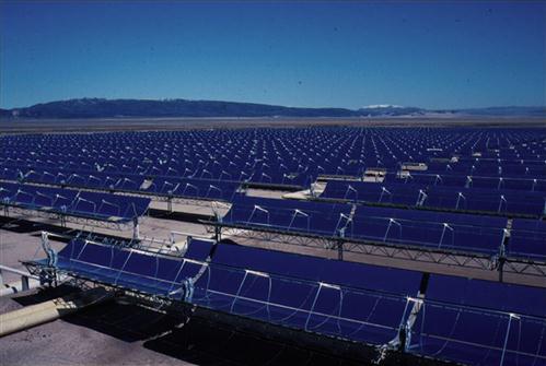
The parabolic trough solar thermal electricity generation system (TSTEGS) collects high-temperature thermal energy by cascading a large number of parabolic trough concentrating collectors. Then a heat medium in the pipelines produces super-heated steam and drives a steam turbine generator to generate electricity. LUZ Solar Thermal Electricity Generation International Co., Ltd built 9 plants successively, with a total capacity of 354 MW, in the Mojave Desert region of Barstow, California, from the middle 1980s to the early 1990s (Fig. 1.4). The company was trying to reduce the generation cost from 24 cents/kWh to 5 cents/kWh, but, unfortunately, the company’s bankruptcy led to the stop of the study plan.
TSTEGS replaced the point focusing with line focusing, and the focusing pipeline tracked the sun together with the cylindrical parabolic mirrors. TSTEGS solves the problem that the light heat conversion efficiency is not high due to the nonuniform focusing spot, lifting the light heat conversion efficiency to approximately 70%. But the parabolic trough solar thermal system also brings three new problems: (1) The system cannot track the sun with a fixed angle, and the tracker is cumbersome and unwieldy. The solar receiver (focusing pipeline in the core of the tractor) is fixed in the reflector trough and moves together with the reflector, resulting in a relatively bulky system. Meanwhile, the connection section of the heat pipe must be active and this structure is likely to damage the insulation and break down. (2) Its wind resistance ability is poor, and not suitable for working in the wind. Each parabolic trough reflector is a larger body of the lens with the size of 99 m long and 5.7 m wide. The wind resistance is very large. So the existing trough type solar thermal power generation system is commonly used in desert regions with no wind or breeze environment that are significantly different from the windy environments in northeast China. An improvement must made to reinforce the mirror supporting structure to strengthen the wind resistance performance of the parabolic trough reflector before it can be successfully applied in China. But, without doubt, it will inevitably lead to a sharp rise in initial investment cost and thermal power generation cost. (3) The receiver of the trough system is long, and the cooling area is large. The solar receiver of the TSTEGS is a very long heat pipeline. Though many new light-absorbing technologies have been developed, its heat dissipating area is much larger than its light-absorbing area. When compared with other typical concentrator systems, the TSTEGS is relative bulky.
1.1.3.3 The Dish-Stirling solar power plant system [64,97–103]
The Dish-Stirling solar power plant system (Fig. 1.5) takes advantage of rotating parabolic mirrors to collect solar radiation energy to drive electricity generators. As with the trough-type system, parabolic dish solar receivers are not fixed. Dish mirrors track the movement of the sun to eliminate the large energy loss of cosine effect in the solar central power tower system, so the thermal conversion efficiency is significantly improved. However, unlike the trough type system, the trough receiver focuses the sun radiation on the focal line of the parabolic surface while the dish receiver focuses solar radiation on the focus of the parabolic dish. This significantly improves the temperature performance of the dish-type system. In 1983, the Jet Propulsion Laboratory in California built a Dish-Stirling solar thermal power system with a concentrator diameter of 11 m, a maximum power output of 24.6 kW, and a conversion efficiency of 29%. In 1992, a German company developed a Dish-Stirling solar thermal power system with an electricity generation capacity of 9 kW, with a peak efficiency of 20%.

The challenges of the Dish-Stirling systems are: (1) the cost of the system is the highest among the three systems. The initial investment cost of the dish-type thermal electricity generation system is as high as 47000–64000 yuan/kW; (2) although concentrated the ratio of the dish system is very high, up to 2000°C, under the present thermal power generation technology situation, there is no need of such a high temperature, because the too high temperature will damage the system. So, the receiver of the dish-type system is not at the focus point generally. It is always set in a low-temperature region in accordance with the performance requirements. The advantages of a high light concentration is not displayed; (3) hot melt salt heat storage technology cost is high and dangerous.
1.1.3.4 The solar photovoltaic power generation system [70,72,73,75–77,105]
The solar photovoltaic power generation system is mainly composed of photovoltaic cells, a solar controller, a storage battery, and so on. When the output power is required to be 220 V or 110 V, an inverter is necessary. The development of solar photovoltaic cells has been very rapid. It has been used in various industry and agriculture fields.
The use of solar energy is growing strongly around the world, in part due to the rapidly declining costs of solar panel manufacturing. In 2011, the global total solar PV installed capacity was 68850 MW, and the corresponding global total solar PV actual generation was 52878 GWh [106].
But the photovoltaic system has the following problems: (1) Chinese domestic solar photovoltaic module manufacturers are small with backward infrastructure and production equipment. Product overall quality is lower than foreign goods. The quality of the local packaging material has not met the expected requirement, and parts of the packaging materials should be imported, which increases the cost. The photovoltaic module production cost is 20% higher than abroad. (2) There is still no uniform photovoltaic power station design and construction specifications at home or elsewhere. So the quality of the system cannot be guaranteed, and the further promotion of photovoltaic power generation will be effected significantly. (3) The amount of money for research and development is limited. The bank loan interest rate is too high. To develop the photovoltaic project, the problem of long-term financing channels needs to be solved. (4) In China, there are no executive incentives to encourage the development of photovoltaic power generation, such as tax, subsidy, photovoltaic grid, reasonable electricity price policy, etc. (5) The lack of infrastructure, small local production capacity, poor sale and service, consumer unawareness, and no new products put into markets will significantly limit the development of solar photovoltaic system.
1.2 Solar Chimney Power Plant System
1.2.1 The Appearance of a Solar Chimney Power Plant System
In order to achieve coordinated development of China’s energy and environment, conventional energy generation technologies are not enough. The use of the existing new energy technologies can not completely solve the problem, so we must continue to seek some alternative ways to solve the problems. We should solve not only the problem of energy exploitation, but also the problem of sound ecological environment protection. Only in this way, can we ensure the sustainable development of the Chinese economy. In terms of power generation technologies, the costs of developing the solar photovoltaic and thermal power generating technologies, including tower, trough, and Dish-Stirling systems, are not able to compete with coal-fired power stations. Thereby, constructing large-scale power plants in MW scale and above are not feasible.
The solar chimney power plant system (SCPPS), sometimes called solar updraft tower (SUT), is a renewable energy power plant for generating electricity from solar radiation [107]. The system is composed of four parts: chimney, collector, energy storage layer, and power conversion units (PCU) (Fig. 1.6). The main objective of the collector is to collect solar radiation to heat up the air inside. As the air density inside the system is less than that of the environment at the same height, natural convection affected by buoyancy, which acts as the driving force, comes into existence. Due to the existence of the chimney which is erected in the middle of the collector, the cumulative buoyancy results in a large pressure difference between the system and the environment. The heated air then rises up into the chimney with great speed. If an axis-based turbine is placed at the bottom of the chimney or near the outlet of the collector where there is a large pressure drop, the potential and heat energy of the air can be converted into kinetic energy and ultimately into electric energy.

The idea of utilizing the solar chimney technology in power generation was originally put forward by Isidoro Cabanyes in 1902 [108]. In 1970s, Professor Schlaich restated this idea in some conferences [109] and built an SCPP prototype in Manzanares, Ciudad Real, 150 km south of Madrid, Spain [110–113]. The height of power station chimney was 194.6 m, the diameter of the chimney was 10.8 m, and the collection radius was 122 m. The canopy of the collector sloped from the inlet to the center, with the height increasing from 2 to 6 m linearly. The plant design capacity was 50 kW while the actual average power output was 36 kW. During the 7 years continuously running period, the average chimney exit air velocity was 15 m/s under the condition of no-load. The full load average speed was 9 m/s with a low operation cost. Researchers spent 9 years continuously improving the design. During the 7-year service time, the power plant’s running time exceeded the expected 95% [114,115]. The power plant operated for approximately 7 years. The tower’s guy-wires were not protected against corrosion and failed due to rust and storm winds. The tower blew over and was decommissioned in 1989 [116]. From then on, the research on SCPP attracted worldwide attention.
1.2.2 Advantages of SCPPS
The SCPPS is a not new type of solar power generation system as it was verified several decades ago. However, when compared with the traditional power generating methods, it has the following advantages: easier to design, more convenient to draw materials, lower cost of power generation, higher operational reliability, fewer running components, more convenient maintenance and overhaul, lower maintenance expense, no environmental contamination, continuous stable running, and longer operational lifespan. In addition, it can partly meet the electricity demand in developing countries and regions where traditional power resources are limited. In more detail, its primary characteristics are manifested in the following aspects:
1.2.2.1 Large scale renewable energy collection
Low energy flux density is the shared characteristic of almost all renewable energy sources; and how to collect renewable energy at a large scale becomes a challenge to all renewable energy technologies. Low energy flux density and large sunshine fluctuation are the fundamental characteristics of solar radiation, and they are also an insuperable barrier for humans in the large-scale exploitation and utilization of solar energy. However, by building SCPPS with an output power of up to 100 MW, the diameter of the collector area will be several kilometers, and it is easy to collect a large amount of low-density solar energy at a low cost.
1.2.2.2 Energy storage with low cost
Considering the fluctuation and intermittence of renewable energy resources, energy storage systems play a significant role in renewable energy technologies, especially the renewable energy power plants. There are many different energy storage technologies [55,117–121], but their prices are very high and the corresponding storage capacities can last only a few hours. The underground materials of the collector serve as a large energy storage system. The solar radiation hits the ground surface through the transparent collector canopy and heats the ground materials. The solar energy is thus stored and releases continuously to the air within the collector canopy which keeps the system operating uninterrupted even on rainy days. The energy storage materials under the collector can be soil, sand, stone, and hermetic water. These materials are very cheap and easy to get in any local area. In the daytime, the energy storage materials can absorb and store energy under direct sunlight. At night, with the radiation condition changes, the heat is released to sustain a stable power output.
1.2.2.3 Air as working fluid
For the SCPPS, air is the only working fluid without phase change. The solar radiation energy resource is abundant in West China. Most areas there suffer from severe water shortage and, therefore, it is not feasible to construct large-scale power systems using water as a working fluid and/or water as a cooling fluid [51,97,122]. Since the working fluid of SCPPS is air, there is no phase change, no water demand, no working mediums, or cooling equipment device in the operation process, which significantly reduces the complexity of the system.
1.2.2.4 Technical feasibility
The SCPPS are composed of a collector, a turbine, a chimney, and an energy storage layer. All these technologies are available and widely used. A key novelty of SCPPS is that it combines these simple technologies to generate electricity without any difficulty. The moving parts are only the turbines and generator, and as a result, the operation and maintenance cost is very low. In addition, the construction, operation, and maintenance of the SCPPS will provide large numbers of jobs for the local people, which is a unique advantage of constructing this type of power station in developing countries.
1.2.2.5 Environmental remediation
Generally, the SCPPS is built in deserts and useless land, and this technology can thus take advantage of the western desert land without immigration needed. Compared with the large hydropower station, SCPPS does not significantly change the local environment and climate. Further, this technology can improve the environment and ecosystem of western China by alleviating the water and electricity shortage. SCPPS can partly take the place of fossil-fired power plants and reduce CO2, SO2, and NOx emissions. Meanwhile, it can be employed to improve the local environment by taking advantage of the its greenhouse effect.
1.2.2.6 Competitive investment and operation costs
The system is simply designed and the building materials, such as glass, cement, steel, are available in the local area. The construction cost of the power station is acceptable, with initial investment being expected to be similar to the cost of building a hydropower plant with the same installed capacity. Land covered by the collector can be reused to plant flowers, grass, and vegetables, which will also increase the air humidity and thus improve the air quality of the ambience around the SCPPS.
1.2.3 Weaknesses of SCPPS
However, an inevitable problem is that the overall efficiency of SCPPS is relatively small. The overall efficiency of the SCPPS is influenced by the greenhouse efficiency of the collector, the updraft efficiency of the chimney, the thermal to mechanical efficiency of the turbines, and the mechanical to electrical efficiency of the generators. The chimney plays an important role in increasing the overall efficiency of the SCPPS; the higher the chimney, the higher the overall efficiency. The collector is a colossal solar energy collection system; the larger the collector diameter, the larger the system output power and energy being stored. So this kind of power stations is not suitable for those areas near metropoles where the land is very expensive.
Considering the commercial application of an SCPPS with an output power up to 100 MW, the collector diameter should be several kilometers, which will cause difficulty in cleaning the collector canopy; the chimney should be about 1000 m, which will be a challenge for construction as there are no buildings in the world this high presently.
1.3 Research Progress
1.3.1 Experiments and Prototypes
The concept of the solar chimney has been proposed for over 100 years. In 1903, Isidoro Cabanyes, a colonel in the Spanish army, was originally proposed a solar chimney power plant in the magazine La energía eléctrica (Fig. 1.7) [123]. In 1926 Professor Engineer Bernard Dubos proposed to the French Academy of Sciences the construction of a Solar Aero-Electric Power Plant in North Africa with its solar chimney on the slope of a large mountain (Fig. 1.8) [123]. In 1931, a German researcher, Hanns Günther advanced a solar chimney power generating technology [124], this technology simply used the stack effect and greenhouse effect to drive a turbine. Several decades later, this technology did not draw the researchers’ attention until Professor Jörg Schlaich, a Stuttgart University, put forward the same idea again in a conference in 1974 [109].


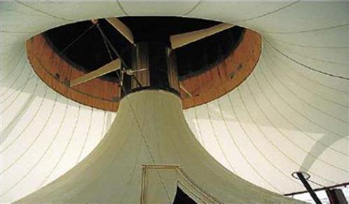
In 1976, Professor Schlaich thought of electricity generation by using the updraft effect, when he was studying the use of circulating water cooling towers to cool the nuclear plant up to 800 m high. Four years later, Professor Schlaich proposed the concept of solar chimney power generation at the annual German Energy Conversion and Utilization Meeting [109]. Professor Schlaich’s thought immediately aroused a heated discussion of the participants and the former West German government attached great importance to it. In 1981, the former West German government research department, cooperating with the Spanish Electricity Company, provided 15 million Deutsche mark to build the world’s first solar chimney power plant prototype in Manzanares, 150 km south of Madrid [110–112] (Fig. 1.9). The system is composed of a chimney 200 m in height and 10 m in diameter, a greenhouse collector with a radius of 122 m and a height of 2–6 m from the periphery to the center (Fig. 1.10), and a controllable wind turbine with a rated power of 50 kW (Fig. 1.11). The chimney is erected in the center of the collector and is fixed by cables (Fig. 1.12). Based on this prototype, Haaf [114,115] and Lautenschlager [125] carried out detailed research on the experiment system design standard, energy balance, cost analysis, the experimental results, and the design strategies for different scale solar thermal power generation system.


Since then, researchers from many countries have built solar thermal power generation systems of different sizes and types. In 1983, Krisst [126] made a “backyard” SCPPS experiment device in West Hartford, Connecticut in the United States. The height of the instrument stack was 10 m, and the diameter of the collector was 6 m with the output power up to 10 W. In 1985, Kulunk [127] built a miniature SCPPS demonstration unit in Turkey Izmit. The device stack was only 2-m high, the chimney diameter was 70 mm, and collector area was 9 m2 with an average power output of 0.14 W. Kulunk reported that the turbine shaft power was 0.45 W, the electricity generating efficiency was 31%, the chimney inlet and outlet temperature difference was 4 K, and the differential pressure was 200 Pa.
In the 1990s, the research group of Professor Sherif [128–133] built three different types of small-scale SCPP model at the University of Florida in Gainesville, United States (Fig. 1.13) and conducted a series of experiments to verify the operating mechanism and energy storage performance. The test units made significant improvements in the following two aspects: (1) The outside edge of the collector was made of the slope type extension; (2) The heat storage medium was introduced as a heat absorber. The extension of the collector area helped to raise the air temperature, and the heat storage medium not only increased average air temperature, but also increased average the mass flow rate. These two approaches increased the output power of the system. The researchers conducted detailed experiments on the system. They obtained the impacts of the solar radiation, the chimney height, collector radius and heat storage layer on stream temperature, speed, and the output power of the system. The cost of investment for different scale SCPPs was predicted, and the results were encouraging, which indicated that large-scale solar thermal power generation system was feasible.

A 3000-m2 solar pond was constructed in Pyramid Hill as part of the facilities of the Pyramid Salt Company in northern Victoria (Fig. 1.14) [134]. The pond was commissioned in June 2001 and reached a temperature of 55°C in February 2002. It has the capability of producing a minimum of 50 kW heat on a continuous basis. Later, the concept of combining a salinity gradient solar pond with a chimney to produce power in salt affected areas was examined [135]. Firstly the causes of salinity in salt affected areas of Northern Victoria, Australia are discussed. Existing salinity mitigation schemes are introduced and the integration of solar ponds with those schemes is discussed. Later it is shown how a solar pond can be combined with a chimney incorporating an air turbine for the production of power. Following the introduction of this concept the preliminary design is presented for a demonstration power plant incorporating a solar pond of area 6 hectares and depth 3 m with a 200-m tall chimney of 10-m diameter. The performance, including output power and efficiency of the proposed plant operating in northern Victoria is analyzed and the results are discussed.

Zhou et al. [136] designed and built a pilot solar chimney power setup in Wuhan China, in December, 2002 in order to investigate the temperature field as well as to examine the effect of time of day on the temperature field (Fig. 1.15). The collector roof was made of glass with a thickness of 4.8 mm, and chimney was made of PVC [137]. In order to avoid diffusing heat through the collector canopy by convective heat transfer, a heat insulator was used to pack the steel-frame structure of the collector. In addition, several pipes with a diameter of 6 cm containing water were paved on the surface under the collector as the energy storage system to store solar radiation. Above the water pipes, one centimeter thick composite layer bed with asphalt and black gravel was applied as the top layer to absorb solar radiation, and then heat was transferred from the top layer to water pipes. At the entrance of the chimney, a multiple-blade turbine was designed and installed to test the power output of the pilot SCPPS. A shield was installed a few centimeters above the chimney top to avoid ambient crosswind entering down into the chimney [136].

In 2007, Koyun et al. [138] built a pilot solar chimney on the campus of Suleyman Demirel University-RACRER (Research and Application Center for Renewable Energy Resources), in Isparta, Turkey (Fig. 1.16). The prototype had a chimney with a height of 15 m and diameter of 1.19 m and a glass covered collector 16 m in diameter. The greenhouse area was about 200 m2, and the inlet area in the periphery of the collector was 31.15 m2. Both experimental studies and theoretical modeling have been performed to test the design.

In 2008, Ferreria et al. [139] built a physical prototype in Belo Horizonte, Brazil for food drying. In this pilot prototype, a tower 12.3 m in height was constructed with sheets of wood and covered by fiberglass at a diameter of 1.0 m. The cover with a diameter of 25 m was made of a plastic thermo-diffuser film. The cover was set 0.5 m above the ground level, using a metallic structure. The absorber ground was built in concrete and painted in black opaque (Fig. 1.17). Ferreria et al. [139,140] and Maia et al. [141–144] presented a series of theoretical analyses and experiments on the system for food drying. The results indicated that the height and diameter of the tower are the most important physical variables for solar chimney design.

In 2011, Kasaeian et al. reported a SCPPS prototype at the University of Zanjan, Iran [145]. The construction of the chimney required the use of 10 iron cylindrical barrels with a height of 1.6 m and a diameter of 0.2 m. These barrels were butt-welded. To maintain the chimney, two collars were used at 6.5 and 12.5 m above the ground. For each of them, steel cables were used. A turbine was installed at a height not exceeding 0.55 m. the platform of the turbine was installed downwardly. The blades of the turbine were made of aluminum. The diameter of the turbine (vertical axis) chosen to prevent air leakage was equal to 0.36 m (Fig. 1.18).

Without any shadow of a doubt, energy production based on renewable energies is one of most fundamental methods for energy generation for the near future. After designing and making a solar chimney pilot power plant with a 10-m collector diameter and a 12-m chimney height, the temperatures and air velocities were measured. The temperature and velocity readings were carried out for some specified locations within the collector and chimney with varying parameters on different days. Because of the greenhouse effect happening under the collector, the temperature difference between the collector exit and the ambient reached 25°C, which caused a creation of air flow from the collector to the chimney. The air inversion at the bottom of the chimney was observed after sunrise, on both cold and hot days. The air inversion appeared with increasing solar radiation from a minimum point and after a while, it was broken by the collector warm-up. After the inversion breaking, there would be a steady air flow inside the chimney. The maximum air velocity of 3 m/s was recorded inside the chimney, while the collector entrance velocity was zero.
Kalash et al. [146,147] reported a pilot sloped solar updraft power plant system (SSCPPS) built in the south campus at Damascus University, Syria (Fig. 1.19). The sloped solar collector has a triangular shape and is tilted at 35° toward the south with an approximate area of 12.5 m2. The chimney height is 9 m and the diameter is 0.31 m. Eighteen temperature sensors were installed inside the sloped solar collector to measure glass, air, and absorption layer temperatures at different points along the collector. Practical data were recorded every 10 minutes for a total of 40 consecutive days to investigate the temperature changes in the sloped collector. Experimental results indicated that, although measurements were taken during the winter season, the air temperature increased to reach a maximum value of 19°C, which generates an updraft velocity in the chimney with a maximum value of 2.9 m/s. As a result, the solar radiation and the ambient temperature have a direct impact on varying the air temperature between the collector outlet and the ambient. It was also noticed that the absorption layer emits most of its stored thermal energy, which is absorbed from the morning to noon, back to the collector air in a short period of time when solar radiation starts to decrease in the afternoon.

In 2010, Wei et al. [148] built a new solar updraft power plant combined with a wind energy system to generate electricity in a desert of Wuhai, Inner Mongolia of China (Fig. 1.20). The chimney height was 53 m and the diameter was 10 m. The collector canopy covered an area of 5300 m2. It was designed based on the solar updraft power by adding some controllable air intakes. There are several air intakes facing north in order to absorb the natural wind, and this can take advantage of the natural wind energy to generate electricity. Thereby, the solar updraft power plant combined with wind energy can be applied on both solar radiation and wind energy for power generation. It was reported that the output power of the system was 200 kW connected to the grid in October 2010.

1.3.2 Theory Research
1.3.2.1 The thermodynamic theory for the circulation system
In 1980, Schlaich [109] gave the first preliminary description of the thermodynamic processes of a solar thermal power generation system in a conference paper. In 2000, Gannon and Backström [149] regarded the working medium flow in the solar thermal power generation system as a standard closed ideal Brayton cycle. The working medium in the whole collector, that is, from the inlet of the collector to the outlet, experienced a constant pressure absorption process. From the bottom of the chimney to the outlet, the working medium underwent an isolation expansion process. The working medium from the vent outlet cooling to the environment temperature was a constant pressure heat release process and the working medium from high altitude down into the collector could be considered as a heat isolation compression process. Process parameters and equations of the above four processes were obtained and the overall efficiency of the system was calculated. Then they analyzed the actual process of the system and the influence of loss in each actual process on the performance of the system.
Energy conversion efficiency of solar thermal power generation system is another important consideration of thermodynamic theory. While in the early research on solar thermal power generation system, Schlaich et al. [109,113,116,150], Haff et al. [114,115] and Lautenschlager et al. [125] raised the mathematical models to calculate the energy conversion efficiency of the system. The calculations showed that the total energy conversion efficiency of the test plant model in Spanish was very low, only about 0.1%. As for large-scale solar thermal power generation system, its effectiveness can reach 1%. In 1985, Louis [151] made an analysis on conversion efficiency from thermal energy to kinetic energy in the greenhouse. He thought, in the greenhouse of the solar thermal power generation system, the infrared radiation and evaporation of water were two significant energy loss ways. By arranging covering material with high transmissivity for short wavelengths and lower transmissivity for long wavelengths, we can actually reduce the loss.
The concentration of rainwater on the roof of the collector was also a factor to influence energy loss, so a method should be developed to make it leave the roof successfully. In addition, the author put forward the hybrid system for the Solar Chimney Power Plant, which had high irrigation and crops cultivation efficiency. In 1987, Mullett [152] established a complete mathematical model to calculate the overall effectiveness of SCPPS with different sizes based on the principle of energy conservation and heat and mass transfer mechanism. He studied the main factors influencing the efficiency of the system, and forecast, calculated, and analyzed the efficiency of SCPPS by researching the Spain model and plants with power generation capacities of 10, 100, and 1000 MW. Predicted calculation results showed that the system overall efficiency was closely related to the size of the SCPPS. The larger the system scale was, the greater the system overall efficiency was. The efficiency range of the large-scale system was 0.96–1.92%.
Gannon and von Backström [149] not only established the thermodynamic cycle model, but also established the power generation efficiency model for SCPPS. Firstly, they analyzed the standard cycle of the ideal gas in the SCPPS and put forward the relationship between the limiting performance, ideal efficiency, and the main variable characters. Then he carried out a detailed analysis of energy losses in each particular part of the system, including friction and local kinetic energy losses in the chimney, heat collector, and turbine. He obtained the function relation between the limit performance of the actual system, the ideal efficiency, and the main variable characters. Finally, based on the Spanish test plant, Gannon carried out an analysis to verify the accuracy of the theoretical model. He also predicted the performance parameters, such as the efficiency and output power of a large-scale power system.
In 2000, Michaud [153] applied the closed thermodynamic cycle for the ideal gas to analyze rising air natural convection process, distinguishing it from the Brayton gas turbine cycle. He utilized the average temperature method to simulate the heat endothermic process of the heat source and the exothermic process of the cooling source, resulting in a conclusion that air heat conversion efficiency is close to the Carnot cycle efficiency. Analysis results showed that the efficiency did not depend on whether the updraft was continuous, and whether the heat transfer was in a latent or sensible way. Since then, he made an analysis of the efficiency of the system and the availability of the SCPPS. In 2006, Ninic [154] analyzed the thermodynamic cycle of the SCPPS system. When the working medium went through the collector, the air got available energy. Based on this, he established the function relationship between the air available energy and the heat absorbed, air humidity, air pressure, and height. Then he analyzed the influence of dry air and wet air on the performance of SCPPS system. A model to describe the relationship between air available energy and chimney height was established along with the possibility of replacing the chimney with wind turbine.
There are some problems with the thermodynamics theory of SCPPS. On one hand, Gannon’s Brayton cycle was based on the total pressure and absolute temperature. At the same time, he took into account the kinetic energy loss in the cyclic graph, which violated the principle that the points on the cycle graph were status points. On the other hand, energy conversion efficiencies, including limiting efficiency, actual efficiency, and energy efficiency, for different SCPPSs did not compare. Energy losses in every part of the system did not analyze.
1.3.2.2 HAG effect of the system
Where did the driving force of solar thermal power generation system come from? Many researchers named the engine as the Helio-Aero-Gravity Effect (HAG Effect) [155–157]. The mechanism of the HAG effect can be explained as follows. When the sun radiation went through the transparent canopy of the collector, the heat storage layer’s temperature rose up. Heat released from the heat storage layer warmed the air near the ground surface. Then the density of the air under the canopy decreased. A large buoyancy force in the chimney aroused strong updraft air flow.
Obviously, the factors influencing the HAG effect were solar radiation, air density, and the earth’s gravity. Existing research has shown that the system drive force caused by HAG effect can be written as follows [109,113,114,116,152,155–157]:
(1.1)
Eq. (1.1) was widely used in SCPPS [150,158–160]. Meanwhile, Mullet [152] thought HAG effect originated from the pressure difference between the chimney bottom and outlet. Researchers who hold the same viewpoint included Lodhi [155,157] and Sathyajith [156], etc. This opinion aroused some misunderstandings. In addition, the description of the driving force based on the mathematical model of HAG effect was a little bit too simple. Eq. (1.1) cannot correctly predict the HAG effect for different geometric structure, environment conditions, and solar radiations on the SC systems. In addition, there were no relevant research reports about the influence of the HAG effect on the system parameters, such as the output power and the energy conversion efficiency. Therefore, it was necessary to make a further analysis and research on the system HAG effect.
1.3.2.3 Heat and mass transfer theory in the system
The most active research work on the SCPPS was concentrated on the heat transfer and flow characteristics. In 1984, Jacobs and Lasier [161] regarded SCPPS as a natural convection system driven by solar energy and made a preliminary theoretical analysis. Lodhi [162] studied the solar energy collection and storage characteristics of SCPPS. Bouchair and Fitzgerald [163] thought that heat storage was a critical influence factor that affected the air temperature and buoyancy force inside the chimney. He analyzed the influence of the sun azimuth angle on the energy collecting efficiency of the collector. The numerical calculation results showed that the solar azimuth angle has a decisive impact on the heat absorption process of the collector.
During 1988–1998, Sherif’s group [129,131–133,164,165] at the University of Florida carried out a thorough theoretical analysis for the SCPPS. A set of flow and heat transfer mathematical models were established. Based on the data of experimental SCPPS, Sherif’s team had built a set of internal flow mathematical models to describe the heat and mass transfer processes in the heat collector. In these models, they analyzed the internal thermal resistance’s influence on the energy loss. By examining the chimney internal flow characteristics, they thought energy conversion followed Betz theory. They also analyzed the influence of different collector designs on the heat and mass transfer characters in the heat collector. The experimental results [131] fit well with the established mathematical model based on the calculation results. Since then, in order to facilitate calculation, Padki et al. [164] developed a very simple mathematical model to forecast heat and mass transfer processes and the power output characteristics of the system. The results showed that the deviations of the simplified models were within 6% [133,164].
Bernardes [166,167] established a whole mathematical model of heat and mass transfer processes in SCPPS, and described its characteristics. The model estimated output power of the system and analyzed the influence of system structure parameters and the external environment temperature on the system output power. Comparing the calculated results with the Spanish test plant, the two outcomes matched very well. Later on, the model was used to predict the performance of large-scale SCPPS, the predicted results showed that the chimney height, the turbine pressure drop factor, the diameter of the collector and its optical properties were important parameters of SCPPS.
Serag-Eldin [168] established a calculation model to predict the fluid flow in the SCPPS. The model was made up of the mass, momentum and energy conservation equations, and two turbulence equations. Furthermore, for the first time, he proposed that we should use an actuator dish model to describe the effect of turbine. The model can be used to estimate the influence of the system size on the system output power. Pastohr [169] simulated the Spanish solar chimney test power plant, established heat and flow mathematical model in the heat collector, the heat storage layer, the turbine, and the chimney. The author made two important simplifications: (1) The heat storage layer was regarded as solid; (2) The turbine was considered as a reverse fan. Turbine pressure drop was calculated based on the Betz theory. Comparing the steady-state numerical calculation with the SIMPLE calculation results, detailed improving measures for the mathematical model were put forward. Moreover, Pretorius and Kröger [170] and Bilgen and Rheault [171] established the corresponding mathematical model for SCPPS respectively. They considered the influences of the following factors: solar radiation, earth latitude, and convective heat transfer coefficient, on the SCPP performance. Coetzee [172] established a transient heat transfer mathematical model for the heat collector, chimney, and turbine, considering the influence of solar radiation on the system output power. Furthermore, he designed a new nozzle shape chimney structure and pyramid-shape collector structure and made the design optimization.
The group of von Backström established a compressible air flow heat transfer mathematical model inside the chimney of the SCPPS [173,174]. Research suggested that, compared with inlet air density, chimney outlet air density decreased significantly. A one-dimensional compressible fluid dynamics model was established to describe the influence of factors, such as the chimney height, wall friction, the internal structure, local resistance loss, sudden shrinkage and enlargement in flow channel, on the thermodynamic parameters of the system. They also analyzed the influence of the Mach number, the fluid density and flow velocity on the pressure change inside the chimney. Furthermore, they predicted various energy loss in the large-scale SCPPS and pressure change at the inlet and outlet of the chimney. Finally, they provided a detailed data analysis report for the fluid flow characteristics inside the chimney.
1.3.2.4 The operation principle of the turbine and the design optimization techniques
As early as 1980, Haaf et al. [114] and Schlaich [113] had carried out the preliminary research on the flow mechanism of the axial turbine. In 1985, Kustrin and Tuma [175] pointed out that the installed wind turbine at the bottom of the chimney shall be single stage and based on the pressure type. Only a part of the air flow kinetic energy could be converted to electrical power. Later on, he described the fundamental principle of the turbine and made a calculation to optimize the test plant in Spain on the basis of the wind turbine analysis.
The research group coming from Professor Backström in South Africa [159,176–181] carried out detailed analysis of the characteristic parameters of wind turbine, flow channel design and optimization, the output power, and so on, as well as vast experimental research. Their main work was as follows: (1) They developed the single rotor and introduced the chimney inlet guide vane that induced fluid flow prerotation before entering the turbine. This design helped to reduce the kinetic energy loss at the entrance of the rotor. They gave the performance and efficiency of the two groups of operating experiments with the similar model of turbines. The measurement showed that the design total-to-total efficiency could be increased up to 85–90%, and the total-to-static efficiency could be increased up to 77–80%. (2) They established the output power mathematical model based on fluid flow of the turbine, load factor and degree of reaction. The optimum reaction, the output power, and turbine size for the largest turbine efficiency were obtained by numerical simulations. The measurement results for a 720 mm turbine showed the correctness of the theoretical analysis of the model. For a given SCPPS, experiments demonstrated that the largest turbine total-to-total efficiency can be increased up to 90%. (3) They made a fluid flow numerical simulation in the turbine area of SCPPS, including the inlet guide vane, the turbine set, outlet of the collector and the inlet of chimney regions. Then they analyzed the influence of wall resistance coefficient, the collector height, the chimney diameter, the turbine diameter, and turbine leaf shape on the pressure drop between the inlet and outlet of the chimney. The experimental results, including the internal flow angle, velocity component, and wall static pressure, had good consistency with the prediction made by commercial CFD code.
1.3.3 Economic and Ecological Theory and Feasibility Studies
Since SCPPS gets involved in many important research areas, such as energy, environment, electricity, and construction engineering, research on its economics and feasibility has never stopped. One of the main reasons was the low overall efficiency of the system. Some associated researchers in the international community had questioned the feasibility of the system. But now, the international community has reached a consensus on the economic feasibility of the system, that is, in terms of total investment costs, operating costs, environmental friendliness, etc., the SCPPS is economical and feasible.
Since the 1980s, Schlaich et al. [109,113–116,125,150] have tracked reports on the economy and feasibility of SCPPS. They analyzed the impact of the world current energy situation, environment, and population on the economy. They proposed the construction of SCPPS was an important measure to solve energy problem in the arid and semi-arid areas in undeveloped countries and regions. Mullet [152], Lodhi [155,157,162], Stinnes [182], Dai et al. [183], Onyango et al. [184] analyzed and studied the economics and feasibility of the system. They thought that the construction of SCPPS in underdeveloped areas and deserts was efficient and technically feasible. Beerbaum and Weinrebe [185] made a profound comparison and analysis among the economy of the coal power generation, solar trough thermal power generation, tower thermal power generation, dish thermal power generation, and solar chimney power generation technologies. They gave a detailed analysis of India’s energy situation and solar distribution, and proposed that developing the SCPPS was the most economical and feasible solution for the energy shortage in India. The technology could be vigorously promoted in the Indian desert and underdeveloped regions.
Undoubtedly, SCPPS will bring excellent ecological and environmental effects. Lodhi [157] and Bernardes [186] respectively conducted an in-depth analysis of the environmental impact and life cycle assessment for SCPPS. Compared with the coal power plant, SCPPS can reduce the amount of SOx, NOx, and CO2 emissions, which is an important measure to improve the urban environment and alleviate environmental pollution around the world.
1.3.4 Potential Application of SCPPS
The development of SCPPS was nagged by the low efficiency, complicated design, high initial investment, and huge risks. Based on the actual situation, researchers put forward some new ideas to improve the system.
Michaud proposed the use of hurricane updraft to drive a turbine to generate electricity [153,187]. Papageorgiou’s research group [188–193] proposed a floating solar chimney system, its main purpose was to solve the problems in the construction of the chimney (Fig. 1.21). The research team carried out a series of studies on the floating solar chimney system. They analyzed the thermodynamic cycle, the heat transfer and fluid flow characteristics, output power, the design and optimization of the turbine, and the economic and technical feasibility of the system. Serag-Eldin [194–196], Zhou et al. [197], Cao et al. [198–200], Koonsrisuk [201,202], Kalash et al. [146,147,203], and Li et al. [204,205] presented mathematical models to describe the operation of sloping SCPPS. Many researchers considered using SCPPS for seawater desalination [68,206–212]. Since the 1990s, the design of SCPPS has entered a substantive development stage. Australia, South Africa, India, Egypt, and some other countries have shown great interest in the construction of a particular scale SCPPS to solve the power shortage problem. They believe that human large-scale exploitation of productive solar energy resource in the desert area using cheap and available construction materials was going to be achieved gradually. The plan and design of 100 MW and 200 MW power plants will be realized in the coming years. The construction of a 30 MW solar chimney power plant in Thar Desert of Rajasthan [213], India was proved to be feasible and began to be implemented. But because of the nuclear arms race between India and Pakistan, the plans came to nothing. Allegedly, the power plant location was considered to be difficult to defend against deliberate destruction, leaving the project to be canceled.

Under the financial support of South Africa’s Northern Cape province, Stinnes and his research team have been conducting feasibility studies of SCPPS since 1995 [182]. They planned to build a practical scale SCPPS in Sishen, a remote desert town in South Africa. It is an ambitious program with a solar chimney height of up to 1500 m, a height three times that of the CN Tower in Canada. The diameter of the collector is 4 km. The project was expected to cost 250 million pounds, and power generation capacity was 200 MW. Stinnes compared this cheap, clean power plant with a variety of other power plants. If the power plant successfully operated for 80 years, it was equivalent to two and a half coal-fired power plants or four combined-cycle natural gas power plant with the same power capacity. Even in the worst case, the electricity price of SCPPS was equal to that of the conventional power plants. In the best case, however, the electricity price of SCPPS would be one-third of that of the conventional power plants.
The world’s first large-scale SCPPS with a height of 1000 m is planned to start construction in Mildura, Australia [214], with the support and attention of the federal government (Fig. 1.22). The chief architect of the project was Professor Jörg Schlaich and the planned investment was 700 million Australian dollars (US $395 million). The diameter of the plant collectors reaches 7 km, 32 turbine generator units with rated output power being 6.25 MW would be installed under the chimney. The total annual power generation capacity would be 200 MW, which could meet the living electricity demand for 200,000 residents.

1.4 Research Contents of This Book
Based on the background of the SCPPS, this book will focus on various aspects, such as the further research of the thermodynamic theory, HAG effect, impacts of structural parameters on fluid flow and heat transfer characteristics, energy storage performance, heat and mass transfer characteristics of the SCPP coupled with turbine, SCPPS under ambient crosswind, and experimental results of small-scale demonstration models. Specifically, the main contents for the following sections of this book are as follows.
1. Firstly, the thermodynamic process in all the essential components of SCPPS is analyzed. By analyzing thermodynamic parameters in each process, the thermodynamic cycle in SCPPS is reestablished. Then the maximum thermal to electric energy conversion efficiency of the system is found. Later, the standard Brayton cycle efficiency, system maximum energy conversion efficiency, and output power of the different for different scale SCPPSs is obtained and compared.
2. A comprehensive mathematical model is advanced to evaluate the HAG effect of an SCPPS, in which the effects of various parameters on the relative static pressure, driving force, power output, and efficiency are further investigated as the existing models are insufficient to accurately describe the driving mechanism of SCPPS. Using the SCPPS prototype in Manzanares, Spain as a practical example, numerical studies are performed to explore the geometric modifications on the system performance, which show reasonable agreement with the analytical model.
3. Numerical simulations on air flow, heat transfer, and power output characteristics of an SCPPS with energy storage layer and turbine similar to the Spanish prototype are carried out, and a mathematical model of flow and heat transfer for the solar chimney power plant system is established. The influences of solar radiation and pressure drop across the turbine on the flow and heat transfer, output power, and energy loss of the solar chimney power plant system are analyzed. In addition, the large mass flow rate of air flowing through the chimney outlet becomes the main cause of energy loss in the system, and the collector canopy also results in large energy loss. Further, the influences of the storage layer material, solar radiation, and environment wind on the system performance are analyzed; the impacts of the heat storage medium characteristics on the power generation peak-valley difference are studied.
4. Numerical simulations are carried out on the SCPPS systems coupled with the turbine. The whole system is divided into three regions: the collector, the chimney, and the turbine, and the mathematical models of heat transfer, and flow have been set up for these regions. Using the Spanish prototype as a practical example, numerical simulation results for the prototype with a 3-blade turbine show that the maximum power output of the system is a little higher than 50 kW. Furthermore, the effect of the turbine rotational speed on the chimney outlet parameters has been analyzed which shows the validity of the numerical method. Thereafter, design and simulation of a MW-graded solar chimney power plant system with a 5-blade turbine are presented, and the numerical simulation results show that the power output and turbine efficiency are 10 MW and 50%, respectively, which presents a reference to the design of large-scale solar chimney power plant systems.
5. Numerical simulations were carried out to analyze the energy storage performance of the solar chimney power plant systems with an energy storage layer. Mathematical models were developed to describe the flow and heat transfer mechanisms of the collector, chimney, and energy storage layer, and the response of different energy storage materials to the solar radiation and the effects of these materials on the power output with different solar radiation were analyzed.
6. Ambient crosswind has a complicated influence on the performance of SCPPS both via the collector inlet and via the chimney outlet. To investigate the impact of strong ambient crosswinds on the system output power through the collector inlet and chimney outlet, numerical analysis on the performances of a SCPPS identical to the prototype in Manzanares, Spain, which is exposed to the external crosswind with different velocities, is carried out. A geometrical model including the SCPPS and its outside ambience is built, and the mathematical models to describe the fluid flow, heat transfer, and output power of the whole system are further developed. The pressure, temperature, and velocity distribution of the air in the ambience and SCPPS together with the output power of the SCPPS are analyzed. To overcome the negative impact of strong ambient crosswind on the system performance through the collector inlet, a 2-m high blockage was circularly set a few meters away from the collector inlet.
7. A mini-scale solar chimney prototype has been set up, and the temperature distribution of the system with time and space, together with the velocity variation inside the chimney with time, has been measured. The experimental results indicate that the temperature distributions inside the collector and the effects of seasons on the heat transfer and flow characteristics of the system show great agreement with the analysis, while the temperature decreases significantly inside the chimney as the chimney is very thin which causes very high heat loss.
8. A brief introduction on the future research points of the SCPPS has been presented from the basic theories to the commercial applications.