
Thermodynamic fundamentals*
Tingzhen Ming1,2, Yong Zheng2, Wei Liu2 and Yuan Pan3, 1School of Civil Engineering and Architecture, Wuhan University of Technology, Wuhan, P.R. China, 2School of Energy and Power Engineering, Huazhong University of Science and Technology, Wuhan, P.R. China, 3School of Electrical and Electric Engineering, Huazhong University of Science and Technology, Wuhan, P.R. China
Abstract
A simple analysis was performed on the air flow through a Solar Chimney Power Plant System (SCPPS) and a thermodynamic cycle of the system including the environment was established. Mathematical models for the ideal and actual cycle efficiencies were also established. The research results showed that the ideal cycle efficiency and actual efficiency of the standard Brayton cycle corresponding to a medium-scale solar chimney power generation system are 1.33% and 0.3%, respectively; while the same parameters for largescale solar chimney power generation systems are 3.33% and 0.9%, respectively. Numerical simulations of a commercial SCPPS with output power in the vicinity of 10–20 MW including the collector, turbine, chimney, and energy storage layer were conducted to investigate the key factors that may influence the overall efficiency of the system. Results of the numerical simulations indicate that an increase in turbine efficiency and chimney height would significantly increase the system’s overall efficiency, but an increase in collector diameter and ambient temperature would decrease the system’s efficiency. Solar radiation is another important factor that greatly influences the system’s overall efficiency.
Keywords
Collector; chimney; Brayton cycle; thermal efficiency; energy storage layer
2.1 Introduction
The solar chimney power plant system (SCPPS), which has the following advantages compared with the traditional power generation systems: easier to design, more convenient to draw materials, lower cost of power generation, higher operational reliability, fewer running components, more convenient maintenance and overhaul, lower maintenance expense, no environmental contamination, continuous stable running, longer operational lifespan, is a late-model solar power generation system [1]. No related experimental results on large-scale commercial SCPPS have ever been reported since the first SC prototype was built in Spain in the 1980s, which is mainly because of the excessive early cost required [2,3]. Establishing a large-scale commercial SCPPS of over 100 MW output power requires the financial support of both local government and enterprise. In 1985, Kulunk [4] set up a miniature SCPPS experimental facility. In 1998, Pasumarthi and Sherif [5,6] built three SC models by modifying the shape and radius of the collector or canopy in Gainesville of Florida University, and carried out experiments on the temperature and velocity distributions of the airflow inside the canopy, whose results agree well with the theoretical analysis. Zhou et al. [7–9] presented some experimental and numerical results of a pilot SCPPS.
Some researchers have focused on the thermodynamic analysis of SCPPS. Michaud [10] investigated how updraft and sounding properties affect the work produced in SCPPS when air is raised and shows that the work can be transferred downward. In his work, closed ideal thermodynamic cycles were used to analyze the atmospheric upward heat convection process which was compared to the Brayton gas-turbine cycle. The heat to work conversion efficiency of the atmosphere was shown to be close to the Carnot efficiency calculated using the average temperatures at which heat is received and given up for hot and cold source temperatures, respectively. In addition, the heat to work conversion efficiency is independent of whether the lifting process is discontinuous or continuous, and nearly independent of whether the heat is transported as sensible or as latent heat.
Petela [11] thought that thermodynamic interpretation of processes occurring in these SCPPS components is based on the derived energy and exergy balances. The author presented examples of the energy and exergy flow diagrams showing how the SCPPS input of 36.81 MW energy of solar radiation, corresponding to 32.41 MW input of radiation exergy, is distributed between the SCPPS components. And responsive trends to the varying input parameters were studied. Later, the concept of mechanical exergy (ezergy) of air was applied which allowed for quantitative determination of the effect attributed to the terrestrial gravity field on the component processes of the SCPPS. The utilization of low-temperature waste heat is attracting more and more attention due to the serious energy crisis nowadays. Chen et al. [12] proposed a low-temperature waste heat recovery system based on the concept of the solar chimney. In the system, low-temperature waste heat was used to heat air to produce an air updraft in the chimney tower. The heat source temperature, ambient air temperature, and area of heat transfer were examined to evaluate their effects on the system performance, such as velocity of updraft, mass flow rate of air, power output, conversion efficiency, and exergy efficiency.
Gannon and von Backström [13] carried out a detailed thermodynamic analysis on the thermal cycle and efficiency of the whole system. In their work, they presented an ideal air standard cycle analysis of the solar chimney power plant with the limiting performance, ideal efficiencies, and relationships between main variables. They also analyzed chimney friction, the system, the turbine, and exit kinetic energy losses during operation (Fig. 2.1). A simple model of the solar collector was used to include the coupling of the mass low and temperature rise in the solar collector. The method was used to predict the performance and operating range of a large-scale plant. In addition, the solar chimney model was verified by comparing the simulation of a small-scale plant with experimental data.

Ninic [14,15] presented an analysis on the available work potential of the SCPPS that atmospheric air acquires while passing through the collector. In this research, the dependence of the work potential on the air flowing into the air collector from the heat gained inside the collector, as well as air humidity and atmospheric pressure as a function of elevation were determined; various collector types using dry and humid air were analyzed; the influence of various chimney heights on the air work potential were established; and the possibly higher utilization factors of the available hot air work potential without the use of high solid chimneys were discussed. The results indicated that the vortex motion flowing downstream of the turbine can be maintained under pressure and can possibly take over the role of the solid structure chimney; a part of the available energy potential acquired in the collector would be used to maintain the vortex flow in the air column above the ground-level turbine (Fig. 2.2).

Later, Nizetic and Ninic [16,17] used working potential in turbines at ground level and analyzed the influence of different air state changes in the collector with an emphasis on overall SCPPS efficiency (Fig. 2.3). They performed an analysis for conventional SCPPS for different air temperature increases and also the influence of adding water in the collector. The results revealed that chimney efficiency in the SCPPS can be derived as a special case of the more general theory.

2.2 Thermodynamic Cycle
The schematic drawing of the thermodynamic process of an SCPPS is shown in Fig. 2.4. The significant state points of air flow are as follows:
1. the state of the collector inlet;
2. the state of the collector outlet, which is also the state of turbine inlet;
3. the state of the chimney inlet, which is also the state of the turbine outlet;
4. the state of the chimney outlet;
5. the state of the environment at the same height of the chimney outlet.

Analysis on the thermodynamic process inside the regions, such as the collector, the turbine, the chimney, and the environment, can be referred to [13].
Starting at the inlet of the collector, the working fluid sequentially flows through the turbine, then the chimney, and finally it releases energy into the environment, and again flows back to the collector inlet. Fig. 2.5 shows the ideal standard temperature-entropy diagram for air in SCPPS, including all systematic loss except for the negligible macroscopic kinetic energy of the chimney outlet. The thermodynamic cycle of the working fluid can be, based on the analysis in [14], simplified into the following four basic thermodynamic processes: (1) process 1-2 refers to the constant-pressure heat addition process inside the collector; (2) process 2-4′ refers to the isentropic expansion process under the condition that shaft power is output from the turbine while no shaft power is output from the chimney; (3) process 4′-5 refers to the constant-pressure heat rejection process during which air flows from the chimney outlet to the environmental upper air; and (4) process 5-1 refers to the isentropic compression process during which the air flows from the environmental upper air to the collector inlet. Among the processes mentioned above, process 4′-5 and 5-1 both take place in the environment, and the above four processes compose a closed thermodynamic cycle.

The thermodynamic cycle of the SCPPS is a typical Brayton cycle, but there is an apparent difference between its network and that of a conventional Brayton cycle. The SCPPS ideal cycle 123′4′51 is a reversible cycle without irreversible energy loss. The heat absorbed during process 1-2 occurs in the collector and is the total heat input of the cycle; the output power curve is process 2-3′, but the energy consumed curve is process 3′-4′; and process 5-1, which occurs in the environment, will not consume any technical work from the system. The shaft work by the turbine for the SCPPS can be written as follows:
(2.1)
The energy that is used by the increase of potential energy of the working fluid when flowing through the chimney is:
(2.2)
As is analyzed above, process 5-1 occurs in the environment, which will not cost any technical work from the system. But the energy consumed by process 3′-4′, which does come from the technical work of the system, will be approximately equal to that by process 5-1. Thereby, most of the technical work in the ideal cycle 123′4′51 is used by the increase of potential energy of the working fluid when flowing through the chimney, leaving a mini proportion to be output through shaft work by the turbine installed at the bottom of the chimney. The cycle 123451 represents the actual irreversible Brayton cycle for the SCPPS, including the turbine loss and chimney loss. The shaft work by the turbine for the SCPPS can be written as follows:
(2.3)
The energy used by the increase of potential energy of the working fluid when flowing through the chimney is:
(2.4)
Compared with the results shown in Eqs. (2.3) and (2.4), the value of ![]() will be much higher than that of
will be much higher than that of ![]() .
.
2.3 Thermal Efficiency
Under the condition of steady solar radiation during daytime, the thermal efficiency of the cycle ![]() can be written as follows:
can be written as follows:
(2.5)
where, ![]() can be written as:
can be written as:
(2.6)
Substituting Eqs. (2.3) and (2.6) into Eq. (2.5), we have:
(2.7)
In the equation above, ![]() stands for the pressure drop across the turbine:
stands for the pressure drop across the turbine: ![]() , while
, while ![]() represents the temperature rise of working fluid inside the collector:
represents the temperature rise of working fluid inside the collector: ![]() . In Eq. (2.7), the value of
. In Eq. (2.7), the value of ![]() can be provided explicitly by numerical simulations, which will be strongly related to the following parameters: solar radiation, turbine pressure drop, etc. Thereby, the actual efficiency of the SCPPS will be strongly related to the actual operation process which is controlled by various parameters: solar radiation, turbine pressure drop, ambient temperature, geometric dimensions of the SCPPS, etc.
can be provided explicitly by numerical simulations, which will be strongly related to the following parameters: solar radiation, turbine pressure drop, etc. Thereby, the actual efficiency of the SCPPS will be strongly related to the actual operation process which is controlled by various parameters: solar radiation, turbine pressure drop, ambient temperature, geometric dimensions of the SCPPS, etc.
The ideal thermal efficiency of the solar chimney cycle, if all irreversible losses are neglected, can be expressed as follows:
(2.8)
thus:
(2.9)
According to the characteristics of each process in the Brayton cycle, we can get:
(2.10)
where, ![]() is the pressure ratio:
is the pressure ratio: ![]() . Substituting Eq. (2.10) into Eq. (2.9), we have:
. Substituting Eq. (2.10) into Eq. (2.9), we have:
(2.11)
So the ideal efficiency of the SCPPS is exactly equal to that of the conventional Brayton cycle. When the hot air flows from the bottom through the chimney to the environment, or the same mass of cold air comes from the environment at the same height of chimney outlet to the collector inlet, the energy transfer can be written as:
By integrating this equation, we have:
(2.12)
From Eqs. (2.12) and (2.11), we can obtain:
(2.13)
Thereby, the ideal efficiency of the SCPPS is related to the chimney height and the ambient temperature, if we neglect the difference between the process 5-1, process 5′-1, and process 3′-4′. The analysis result agrees well with that shown in Ref. [13]. This efficiency in Eq. (2.13) cannot be obtained because many influencing factors are not taken into account.
2.4 Results and Analysis
To validate the theoretical analysis and to compare with the results between the ideal efficiency in Eq. (2.13) and the actual efficiency in Eq. (2.7) shown above, three typical types of SCPPs were analyzed by numerical simulation. The mathematical models to describe the flow and heat transfer characteristics can be found in Refs. [11,12], the geometric dimensions for the models can be found in Table 2.1, and the related parameters with the same values are shown in Table 2.2.
Table 2.1
Geometric Dimensions of Three Typical SCPPSs
| Model | Chimney | Collector | ||
| Height (m) | Diameter (m) | Height (m) | Diameter (m) | |
| Spanish prototype | 200 | 10 | 2~6 | 122 |
| MW-graded | 400 | 50 | 2~10 | 1000 |
| 100 MW-graded | 1000 | 130 | 3~25 | 2500 |

Table 2.2
Basic Parameters of Three Typical SCPPSs
| Parameters | Units | Value |
| Transmissivity of canopy | – | 0.9 |
| Emissivity of canopy | – | 0.85 |
| Absorptivity of storage layer | – | 0.9 |
| Conductivity of storage layer | W/(m·K) | 1.2 |
| Thickness of storage layer | m | 2.0 |
| Ambient temperature | K | 293.15 |
| Ambient air velocity | m/s | 2 |
| Solar radiation intensity | W/m2 | 500, 750, 1000 |
| Turbine pressure drop | Pa | 0~1500 |
| Efficiency of turbine | – | 72% |
Boundary conditions are set as follows: For the roof of the collector, we take convection boundary into account, and coefficient of convection is set as 10 W/(m2·K) which can be accepted when the environment air velocity is not very large, that is, 1–2 m/s. The temperature of the environment is set as 293 K, the inlet of the collector is set as the pressure-inlet boundary, the chimney wall can be set as an adiabatic boundary; the chimney outlet is set as the pressure-outlet boundary; the bottom of the energy storage layer is set as the temperature-constant boundary, whose temperature is 300 K. Solar radiation which projects through the transparent ceiling into the ground can be considered as a heat source for the ground thin layer [10]. We can simulate the running conditions of an SCPPS on the whole by setting solar radiation as 500, 750, and 1000 W/m2, respectively. The acceleration of gravity is 9.8 m/s2, and the air density changing with altitude can be found in Ref. [9]. Thereby, the pressure ratio can be calculated accordingly.
In addition, it is necessary to explain the reason for why we consider the collector inlet and chimney outlet both as pressure boundaries and have their pressures set as 0 Pa. This is because we simultaneously take the inner and outer pressure distributions of the system into account, ![]() means that for both the inside and outside of the collector inlet, the static pressures at the same height are the same [18,19].
means that for both the inside and outside of the collector inlet, the static pressures at the same height are the same [18,19].
However, the setting of pressure drop across the turbine in this paper differs from the processing method applied by Pastohr [20]. The turbine of SCPPS, as explained earlier, belongs to a pressure-based wind turbine, the fore-and-aft air velocities are almost the same but the pressure changes significantly, and its power output does not follow the Beetz power limit theory. Therefore, the output power through the turbine can be calculated according to Eq. (2.14) by presetting the pressure drop across the turbine:
(2.14)
where, ![]() represents the shaft power output through the turbine,
represents the shaft power output through the turbine, ![]() represents the energy conversion efficiency of the turbine, which can be preset as 80% (less than the optimized data),
represents the energy conversion efficiency of the turbine, which can be preset as 80% (less than the optimized data), ![]() represents the pressure drop across the turbine, V represents the air volume flow rate of the system flowing through the chimney outlet. The boundary conditions for different places are shown in Table 2.3.
represents the pressure drop across the turbine, V represents the air volume flow rate of the system flowing through the chimney outlet. The boundary conditions for different places are shown in Table 2.3.
Table 2.3
| Place | Type | Value |
| 0.1 mm top layer of the ground | Heat source | 2×10⁶~8×10⁶ W/m3 |
| Bottom of the ground | Temperature | 300 K |
| Surface of the canopy | Wall | T=293 K, |
| Surface of the chimney | Wall | qchim=0 W/m2 |
| Collector inlet | Pressure inlet | pr,inlet=0 Pa, T0=293 K |
| Chimney outlet | Pressure outlet | pr,outlet=0 Pa |

The standard ![]() model is applied during the numerical simulation of air flow in the collector and chimney, the SIMPLE algorithm is applied for pressure-velocity coupling, and the momentum equation, energy equation, and other equations all apply the second-order upwind discretization scheme. The mesh numbers of the 50 kW, MW-graded, and 100 MW-graded SCPPSs are nearly 500,000, 1,200,000, and 2,500,000, respectively, where we can get grid-independent simulation results.
model is applied during the numerical simulation of air flow in the collector and chimney, the SIMPLE algorithm is applied for pressure-velocity coupling, and the momentum equation, energy equation, and other equations all apply the second-order upwind discretization scheme. The mesh numbers of the 50 kW, MW-graded, and 100 MW-graded SCPPSs are nearly 500,000, 1,200,000, and 2,500,000, respectively, where we can get grid-independent simulation results.
2.4.1 Computation Results for the Spanish Prototype
Figs. 2.6 and 2.7 show the numerical results of the SC prototype in Spain. As shown in Fig. 2.6, when the solar radiation intensity is 1000 W/m2, the maximum output power is about 75 kW—about 50% higher than the design value of the Spanish prototype. This is because the efficiency of turbine shown in Table 2.2 is almost 50% higher than the design value which is based on the Betz theory. The efficiency of a conventional turbine, which is used in free wind farms, with a good design based on the Betz theory is a little less than 50%, while the turbines used in the solar chimney systems are pressure-staged turbines and their efficiencies will be higher than 85%. Thereby, the efficiency of the turbine selected in Table 2.2 is acceptable and reasonable.
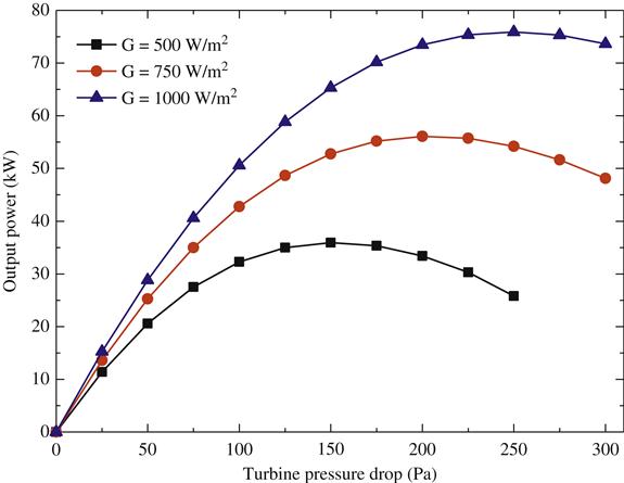

Fig. 2.7 shows the temperature rise of the airflow inside the collector. It can be easily seen that the air temperature rise inside the collector increases significantly with the increase of solar radiation intensity and turbine pressure drop. Apparently, the total pressure drop of the SCPPS is P1–P5, which is exactly determined by the chimney height and the air density distribution along the altitude of the ambience. With the increase of pressure drop across the turbine, the pressure drop by harnessing the air flow through the chimney decreases, and the air flow rate and velocity will decrease. Therefore, the air temperature rise inside the collector will increase. In addition, the air temperature rise inside the collector also increases with the increase of solar radiation intensity. From Figs. 2.6 and 2.7, we can see that the turbine pressure drops according to the maximum output power: when the solar radiation intensities are 500, 750, and 1000 W/m2, the pressures are 150, 200, and 250 Pa, respectively, and the temperature rises are 28.28, 33.04, and 41.65 K, respectively.
Fig. 2.8 shows the effects of pressure drop across the turbine on the cycle thermal efficiency, in which the efficiency curve of the ideal value refers to the efficiency of Brayton cycle shown in Eq. (2.13). From this figure, we can find that the ideal value of the efficiency of the Spanish solar chimney power plant prototype is 0.665%, while the actual efficiencies corresponding to the changing turbine pressure drop of the prototype are all less than 0.2% under different solar radiation intensities. The ideal thermal efficiency of the system is lower than 1%, for which the main reason is that most of the heat energy from the solar energy cannot transfer into shaft work during the isentropic expansion process in the turbine (turbines), it can just be used to overcome gravity when flowing through the chimney.

Moreover, the ideal thermal efficiency of the system is much higher than the actual efficiencies, this is because the increase of the turbine pressure drop results in a larger temperature rise in the collector shown in Fig. 2.7, accompanied by a larger heat loss through the collector canopy and a larger energy loss through the chimney outlet. Therefore, the SCPPS is unable to reach the ideal thermal efficiency level of the standard Brayton cycle shown in Fig. 2.8. In addition, the actual efficiency of the system is strongly related to the geometric dimensions, the turbine pressure drop, the solar radiation intensity, and all the parameters shown in Table 2.2, while the ideal efficiency is only subject to the chimney height and ambient temperature. Thereby, the actual efficiency of the SCPPS can never reach the value of ideal efficiency, and the former will be more useful for the design and commercial application of different kinds of SCPPSs.
2.4.2 Computation Results for Commercial SCPPSS
Now we carry out thermodynamic analysis on an MW-graded solar chimney whose geometric dimensions are shown in Table 2.1, computing for its output power and cycle thermal efficiency. Fig. 2.9 shows the comparison relationship among the efficiencies of actual cycle and the ideal cycle of the MW-graded SCPPS. As shown in this figure, the MW-graded system ideal cycle efficiency is about 1.33%, which is independent of all the actual operational parameters, such as solar radiation intensity and turbine pressure drop. The maximum value of the system actual efficiencies is near 0.3%, which is lower than one quarter of the ideal efficiency value. By comparison, the difference between the actual and ideal efficiencies becomes larger with the dimensions of the solar chimney system, this is because the increase of collector area will decrease the system efficiency due to a larger heat energy loss through the canopy.

The geometric dimensions of large-scale SCPPS are shown in Table 2.1, and the simulation results are shown in Figs. 2.10 and 2.11. As shown in Fig. 2.10, the ideal efficiency of a large-scale SCPPS with chimney height 1000 m is about 3.33%, while the maximum value of the actual efficiencies is about 0.9%. Obviously, the actual efficiency is also much lower than the ideal value, which is also because of much larger heat energy loss from the collector canopy.


Although the actual efficiency of the large-scale SCPPS is not higher than 0.9%, the maximum output power is over 100 MW when the solar radiation intensity is 750 W/m2 or more. Taking into consideration that the SCPP will not consume any fossil energy, the raw material used to build the system is easy to access, and the investment for the system is relatively low, the actual efficiency, which is about 1%, is acceptable for its commercial application.
Further study will focus on the following two points: (1) quantitatively explore the detailed factors which have effect on the actual efficiency; (2) find a new way to increase the total efficiency and output power of the system, for instance: combining the SCPP and the photovoltaic power system to build a new synthetic system to highly improve thermal efficiency of the system.
2.5 Effect of Various Parameters
As we know, it is very difficult to quantitatively present a theoretical analysis of the influences of various parameters on the efficiency of Solar Updraft Power Plant System (SUPPS) due to the strong intercorrelations of these parameters, so numerical analysis on the SUPPS by varying one parameter with the other parameters being constant becomes an effective way to solve this problem. The key parameters influencing the system efficiency are turbine efficiency, system geometrical dimensions, solar radiation, and ambient temperature. These will be discussed one by one.
2.5.1 Influence of Turbine Efficiency
When conducting our simulations to study the influence of turbine efficiency on the system efficiency, the SUPPS structural parameters were selected as follows: the diameter of the collector 2000 m and the height and diameter of the chimney 900 and 90 m, respectively. The solar radiation value was selected as 500 W/m2 and the ambient temperature 20°C. The turbine efficiency was allowed to vary from 0.72 to 0.9, with an interval of 0.06. Simulation results are shown in Figs. 2.12 and 2.13.


According to Fig. 2.12, when the turbine pressure drop is higher than 200 Pa and in a large range, the power output of the system could be over 10 MW with different system efficiencies. Setting the turbine efficiency to 90%, the highest system output power is close to 20 MW. This suggests that it is not too hard to achieve an output power of 10 MW under normal conditions with general solar radiation in the vicinity of 500 W/m2 for this physical SUPPS model.
Fig. 2.13 shows the influence of turbine efficiency and turbine pressure drop on system efficiency. Under certain turbine efficiencies, the system efficiency increases and then decreases with increasing turbine pressure drop. According to Fig. 2.12, there exists a peak value for the product of the turbine pressure drop and outflow volume flux at the chimney outlet though the flux decreases with increasing pressure drop. Thus the system power output and efficiency also have a peak value. Considering that the cost of the turbine is much smaller than that of the collector and the chimney in a given SUPPS, improving the efficiency of the turbine is probably the most effective method to improve the overall system efficiency.
2.5.2 Influence of Chimney Height and Diameter
For the simulations intended to examine the influence of chimney height and diameter on the system efficiency, the height of the chimney was allowed to range from 800 to 1200 m while the diameter varied from 40 to 140 m. The diameter of the collector was set to 2000 m. Solar radiation was selected as 500 W/m2 while the ambient temperature was set at 20°C. The turbine pressure drop and efficiency were set at 800 Pa and 0.72, respectively. Simulation results are shown in Fig. 2.14.

In Fig. 2.14, for a certain chimney height, the system efficiency increases with the increase of the chimney diameter, however the increase of the system efficiency tapers off at some point and we reach a state of diminishing return. Thus, it would probably be advisable to increase the chimney diameter only up to a point (around 100 m) as a way of increasing the system efficiency, and refrain from doing so beyond chimney diameters of 100 m. The effect of chimney height, on the other hand, plays a bit of a different role when it comes to system efficiency. For example, for a chimney diameter of 100 m, the system efficiency increases from 0.98% to 1.4% when the chimney height is increased from 800 to 1200 m. Thus the height seems to be a key parameter to use to increase system efficiency. However, proper chimney height should be chosen taking into account cost issues as an increase in height necessarily translates into an increase in cost.
2.5.3 Influence of Collector Diameter
For the simulations intended to examine the influence of collector diameter on the system efficiency, the diameter of the collector ranged from 1000 to 3000 m, while the chimney height and diameter were set at 900 and 90 m, respectively. The solar radiation value used in the simulations was 500 W/m2 as before, while the ambient temperature remained at 20°C. The turbine efficiency was set at 72%. Simulation results are shown in Fig. 2.15.

The combined effect of the collector diameter and turbine pressure on the system efficiency is a bit complex. For a given collector diameter, the efficiency first increases with the turbine pressure drop and then slowly decreases. For a given turbine pressure drop, the efficiency decreases with an increase in the collector diameter. A part of the energy absorbed by the collector is used to heat the air and increase the air velocity, another part is transferred to the ground, and the rest escapes to the environment via the collector canopy. We could attempt to explain this behavior as follows. When the area of the collector is zero, the flow of air in the system would only depend on the density difference between the air inside the chimney body and the ambient air, with no losses to the ground or the environment. As the collector diameter increases, there will be energy losses to the ground and environment, with an associated reduction in the efficiency of transferring the heat to kinetic energy. Furthermore, it can be seen that the turbine pressure drop for maximum system efficiency increases with the increase in collector diameter. This is attributed to the fact that the increase of the collector area causes the system draft power to increase.
2.5.4 The Influence of the Solar Radiation
In the simulations conducted to study the influence of solar radiation on the system efficiency, the solar radiation was varied from 400 to 800 W/m2 with a 100 W/m2 interval. The chimney height and diameter were kept at 900 and 90 m, respectively. The collector diameter was set at 2000 m. The ambient temperature was kept at 20°C, while the turbine efficiency was set at 72%. Results of the simulations are shown in Fig. 2.16.

As can be seen, the relationship among solar radiation, turbine pressure drop, and system efficiency is a bit complex. When the pressure drop and radiation are both low, most of the input energy is used to heat the air in the system, thus contributing to a higher efficiency. At higher values of the pressure drop, the air flow drops, while the temperatures of both the soil surface and air increase, thus contributing to transferring more energy to the ground and the environment. All of this contributes to decreasing the efficiency. When the solar radiation is higher, only by increasing the turbine pressure drop to produce enough axial work can the system efficiency become higher.
A certain system efficiency value, except the peak, has two corresponding turbine pressure drop values. Low turbine pressure drop causes an increase in the air flow rate, while a higher pressure drop decreases the flow rate and thus contributes to increasing the energy stored. To make the system operate more steadily, it is better to select the higher pressure drop values.
2.5.5 The Influence of Ambient Temperature
To investigate the influence of the environmental temperature on the system efficiency, the ambient temperature was varied from −10°C to 30°C, while the collector diameter was set at 2000 m. The diameter and height of chimney were assigned the values of 90 and 900 m, respectively. The solar radiation was set at 500 W/m2 and the turbine efficiency was set at 72%. The results are shown in Fig. 2.17.

From this figure, it can be seen that, for a certain turbine pressure drop, the system efficiency increases with a decrease in the ambient temperature. When the pressure drop is small, the system efficiency increases slightly with the decrease of the ambient temperature. When the pressure drop is large, the efficiency increases more rapidly with the decrease of the ambient temperature. It is important to design the system so that it operates under turbine pressure drop values close to those corresponding to the efficiency’s peak value.
It should be mentioned, that a lower ambient temperature may not be the best choice for a SUPPS. Generally, in the winter and spring, the solar radiation is comparatively weak, so close attention should be paid to whether all parts are operating normally at lower ambient temperatures.
Overall, various parameters show complex influences on the efficiency of SUPPS. The performance of the turbine seems to be the most important to SUPPS. Increasing the turbine efficiency seems to greatly improve the overall efficiency of SUPPS. Significantly reducing the geometrical dimensions of the system is necessarily associated with a significant reduction of the total construction cost. Higher chimney and strong solar radiation will cause larger driving forces which will greatly increase the system efficiency. For the collector diameter and ambient temperature, decreasing these two parameters will cause higher overall system efficiency. Similarly, decreasing the collector diameter will greatly decrease the amount of solar radiation energy.
2.6 Conclusions
This chapter has made an analysis of the flow of working fluid within various parts of SCPPS and a thermodynamic cycle, starting from the collector inlet, passing through the collector and chimney outlet, and finally back to the collector inlet from the environment. In addition, numerical models for ideal cycle efficiency and actual cycle efficiency are also established. Computations and predictions are carried out for SCPPSs of various scales, and the research results show that: under the same pressure drop as the Spanish solar chimney power plant prototype, the ideal efficiency of the standard Brayton cycle is about 0.665%, while its actual cycle efficiency is less than 0.2%; the ideal cycle efficiency and maximum actual efficiency of the standard Brayton cycle corresponding to medium-scale SCPPS are 1.33% and 0.3%, respectively, while the same parameters for large-scale SCPPSs are 3.33% and 0.9%. The actual efficiency of any type of SCPPS is much lower than the ideal efficiency based on the Brayton cycle, and the former can be used for the design and commercial application of large-scale SCPPSs.
A two-dimensional steady state numerical simulation on a commercial SUPPS to analyze the influence of various parameters on the system efficiency has been presented. Mathematical models to describe the fluid flow, heat transfer, and output power were investigated, employing a method to incorporate the presence of the turbine. Based on the results obtained, we can reach the following findings.
1. The turbine plays an important role in the efficiency of SUPPS. Increasing the turbine efficiency will greatly improve the overall performance of SUPPS and reduce its construction cost. The turbine pressure drop also has a significant influence on the system efficiency, output power, and the energy stored.
2. Chimney height is another key parameter having significant influence on the efficiency of SUPPS. Increasing the chimney height will greatly increase the system driving force, output power, and ultimately the efficiency. But taller chimneys will significantly increase construction costs for a commercial SUPPS. Increasing chimney diameter will be beneficial to system efficiency but will also cause construction costs to rise.
3. Solar radiation is always a positive factor to system performance, so it plays a very important role in the site selection of SUPPS.
4. Increasing the collector diameter and ambient temperature will both have negative effects on the system efficiency. However, the collector is the only solar radiation receiver and without it no output power will be generated.
Nomenclature
cp Specific heat at constant pressure, kJ/(kg·K)
G Solar radiation intensity, W/m2