This chapter will introduce you to basic workflow and features that support early conceptual design and analysis of buildings. We'll look at how to create basic forms and rationalize those forms with surface divisions using the new conceptual design environment. We will then see how to leverage the mass downstream in the design process by applying Revit model elements such as walls, floors, and roofs to mass surfaces.
Topics we'll cover include:
Understanding the conceptual design tools
Rationalizing surfaces
Using model-by-face tools
Within Revit, it is possible to carry a model from early conceptual forms through construction documentation without having to restart the process at each stage in the design process. By creating conceptual forms, and then applying intelligent building elements directly to the form, you can move your design intent forward in the context of a BIM workflow. Revit 2010's form-making tools are designed to support a wide range of forms — from simple boxes to doubly curved surfaces. Regardless of the formal complexity, you'll be able to apply walls, floors, and roofs to those forms and then analyze your design.
Using massing features, parametric capabilities, and integrated scheduling, you can represent and quantify information such as area, volume, and program information.
The early stages of conceptual design rely heavily on sketches, study models, and diagrams to explore ideas before committing to a final concept. With the aid of the computer, these concept sketches can be moved into digital 3D models very early in the process. The models can be edited quickly, and can be used to generate graphics, create 3D printed prototypes, and perform early energy analysis. With a traditional 2D CAD workflow, the work used to generate these early models cannot be transferred downstream when design development begins. The work starts over, a new model is created, and detailed design begins. If the concept undergoes any major revisions, the process starts over again.
Even if you're making study models using digital tools such as Rhinoceros, SketchUp, Form Z, Maya, or 3ds Max, in order to document your design you still need to start from scratch because these tools are 3D modelers — not architectural documentation tools. With the advent of building information modeling, this is all changing, as you can now carry a conceptual model through to construction documentation in one environment.

BIM provides the ability to move and reuse previously created data throughout the design process, from start to finish — without having to start over from zero. With the Revit massing tools, your model can remain integrated. For early concept studies, you can create models natively using Revit's conceptual design tools or by importing geometric massing studies created in other applications. Figure 14.1 shows a concept model that was taken from simple massing shapes to more detailed design, and even printed in 3D. Regardless of whether you create the concept geometry within or outside of Revit, you can generate building elements such as walls, floors, and roofs directly from the geometry.
The conceptual modeling tools in Revit can be accessed directly in the project as in-place family instances, or from a special family template, mass.rft. Mass families can be loaded and placed into a project like any other family. Each method, in-place or a loadable family, offers slightly different behaviors. For example, building a context model of abstract building shapes — which is generally static — makes the most sense to do in the project environment, whereas building multiple concept studies that can be swapped in and out of your site model is better handled with family instances.
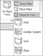
We'll look into how to use both methods. If you're in a project file, you can access the massing features in the Conceptual Mass panel on the Massing & Site tab (Figure 14.2). You'll use this tab to create in-place masses, control visibility of masses, place mass instances, and model Revit elements (walls, roofs, curtain systems, and floors) using the surfaces of masses. If you want to create a massing family, click the Application menu (R) and select New → Conceptual Mass (Figure 14.3).


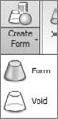
The tools for creating conceptual masses are a bit different than those used to make other Revit families. The Family Editor uses explicit sketch-based tools such as Extrusion, Blend, Revolve, Sweep, and Swept Blend. These tools require you to enter a Sketch mode to make changes to the geometry and lack the ability to interact with the forms directly. With the massing tools, there are no Sketch modes, and form can be manipulated directly. In fact, you won't even see tools for creating extrusion, sweeps, or revolves. Instead, you'll see standard line creation tools, the Create Form tool, and some datum tools (Figure 14.4). Once you make a form, additional tools become available when you select the form, including the ability to add new edges, profiles, and divide surfaces (Figure 14.5).


Once you have made a form, you can then freely manipulate it using interactive controls, temporary dimensions, and parametric dimensions. Click on any surface, edge, or vertex of a form and a control will appear. Use this control to adjust the form. Figure 14.6 shows selection of a vertex, edge, and surface of a form.
Once you've made a form, you can rationalize it by dividing the surface and applying panel families to it directly in the conceptual environment (Figure 14.7), or apply walls, floors, and roofs using the Model by Face tools and Mass Floors tool available in the project environment (Figure 14.8). Dividing a surface always takes place while you are editing the family, and modeling by face takes place when you are in the project environment.
Let's take a look at some of the Revit massing tools:
- In-Place Mass tool
To make a mass in a project, use the In-Place Mass tool on the Massing & Site tab. This will enable the massing tools in a new ribbon tab.

- Place Mass tool
This tool (

- Show Mass tool
The Massing category visibility can be turned on and off with the Show Mass tool (


Figure 14.8. Using Model by Face and Mass floors, you can move from concept mass to building elements quickly

Figure 14.9. When you first create a mass, the category will be made visible with the Show Mass toggle
To see the mass elements in specific views only, use the Visibility/Graphics Overrides settings. When the Show Mass button is turned off and you activate the Mass setting in the Visibility/Graphic Overrides dialog box, the mass category will be visible in that view. Keep in mind that to print and/or export massing, you need to turn the Massing category on using Visibility/Graphic Overrides.
As your design gets more detailed and starts to incorporate real building components such as walls, floors, and roofs, you'll need a quick way to jump back to just the massing forms. A great way to maintain a view where only massing is visible is to create a 3D view where all categories are turned off except the Massing category. To do this, first create a new 3D view, and use the Visibility/Graphics Overrides dialog box.
Figure 14.10 shows two views: one with only the massing category visible and the other with all categories visible. This is handy when you want to make adjustments to the basic shapes that define the geometry (masses) without being distracted by the presence of the building elements.
When you select the In-Place Mass tool from the Massing & Site tab, you're first prompted to name the mass you're about to create. Once you provide a name, you will find yourself in the conceptual mass-creation environment. Using these tools, you start by drawing lines, and then you can create solids, surfaces, or voids. Surfaces can then be divided and patterned, and used as a basis for walls, floors, and roofs. When in a project, the other tabs are still available, and various tools will be enabled or disabled depending on their relevance to massing tasks. For example, the Edit tools (such as Trim and Align) will still be accessible on the Modify tab, and Dimension will be available on the Annotate tab. Other tools, such as walls, floors, and roofs, will be disabled. If you have already modeled building elements, they will not be editable from the in-place massing mode.

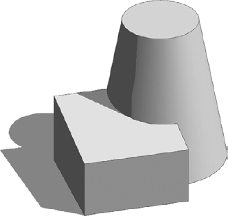
Start by drawing lines in your view using the draw tools (Figure 14.11) — a simple rectangle is a good place to start. When lines are selected, the contextual tab changes to Modify Lines. Clicking the Create Form button (Figure 14.12) will then create a solid box, as shown in Figure 14.13.

Depending on the lines you select, you'll be able to create a wide range for 3D forms. If you draw a series of lines on multiple levels and then create a form from those lines, you'll get a lofted surface.
The tools in the Draw panel provide a set of common line creation methods to create your initial lines. Note that there are two types of lines you can make: lines and references. Lines will be "consumed" into the form when used to make a form, while reference lines will not. That is to say, the lines no longer exist once you make form with them. Reference lines can also be used to host other elements, whereas lines cannot. For example, if you draw lines on a reference line and then rotate or move the reference line, the lines will go with it.
You'll notice that in this environment, you will not need to press Tab to select a chain of lines.
Everything you add in the mass editing session will create a single mass instance when you finish. Your decision to create individual shapes as separate mass elements or as a collection of masses depends on how you intend to interact with your mass instance. For example, one mass element could have five boxes representing five buildings. Or, you could make five separate mass elements for each building. Do you want to move each building independently? Or will you likely want to move all the buildings together as a single object? These kinds of questions should guide your decision-making process.
Once you've made a form, some controls will show up when the mass is selected. The controls let you edit directly by dragging the triangular control grips on the form (Figure 14.14), and they only show up on planar surfaces. The controls do not provide temporary dimensions, and dragging will result in hard-to-predict numeric values. Rather than deal with these grips, it is easier to simply select the form and edit it in-place. You'll get better interaction and more precise controls with the arrow controls (Figure 14.15).

Figure 14.14. When a mass is selected, triangle grips appear on the form; you can drag these and change the form
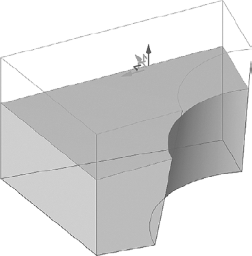
Figure 14.15. For more precise editing and less visual noise, edit the form in-place and select the surface, edge, or vertex you want to edit
When you have a surface, edge, or vertex selected, you'll be able to use the arrow control. Press the spacebar to change the orientation of the control to align with local geometry. This is useful if the geometry you are working on is not aligned to the global XYZ coordinates. Note that if the local geometry is aligned with the global XYZ axis, the control will not change appearance with the spacebar. Figure 14.16 shows the different orientation of the control when you use the spacebar to toggle it.
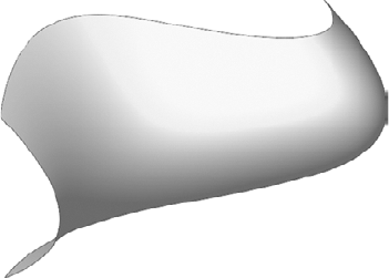
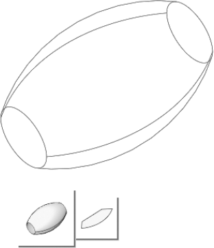
Figure 14.17. Surfaces, such as this loft, can be created in the conceptual massing environment; however, they cannot be joined to solids
The conceptual tools support essential Boolean operations, such as cutting and joining of intersecting forms. It is important to note that massing forms can be solids or surfaces — something new to the 2010 release (Figure 14.17). However, surfaces cannot be used to cut into solids. We'll explore the range for form topologies later in the chapter, in the section "Understanding Form Making and Rationalization."
Any form can be either solid (positive form) or void (negative form), and can be changed back and forth at anytime using the Convert to Solid/Convert to Void toggle in the Form tab. Voids will automatically cut into solids. Try making two boxes — one void and one solid — using the options in the Create Form drop-down. If the two forms intersect, the void will cut away geometry from the solid.
Voids, as the name suggests, create negative volumes that carve away from solid forms, as shown in Figure 14.18. A void will automatically cut solids when they intersect, unless you tell it not to cut using the Don't Cut tool on the Modify tab.

Multiple forms can be joined to one another to create connected forms. This tool joins solids to form one connected element (note that voids can't be joined together). It merges the shapes (masses) into one, both graphically and as data (Figure 14.19). To use this tool, select the tool, and then select the solids you want to join. Multiple solids can be joined together. The Join and Unjoin Geometry tools (Figure 14.20) are available on the Modify tab.
We've looked at the basics of how to get started on a massing form. Now we'll dig into how to actually create some common forms, and then rationalize forms using the surface division tool. In the following exercise, we'll guide you through the creation of several types for forms that you can make with the conceptual modeling environment, including extrusions, lofts, sweeps, and revolves. The result will be mass shapes similar to those shown in Figure 14.21.
First, when you're creating a new mass, it's essential to select the correct family template. Be sure to use Mass.rft or Metric Mass.rft — the default template from the Application Menu, and choosing New → Conceptual Mass. Follow these steps:
From the Application Menu, choose New → Conceptual Mass. In the New dialog box, select the template
Mass.rftorMetric Mass.rftand click the Open button.Using the rectangle tool from the Draw/Pick Gallery, draw a rectangle on Level 1 (Figure 14.22). This will be the default work plane, and will highlight as you draw the rectangle.
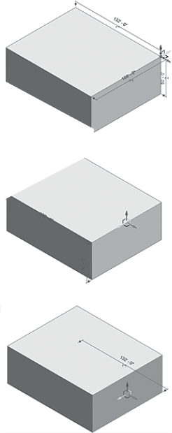
Select the lines, and click the Create Form tool. A box will appear, with a temporary dimension to the top of the box. Click the dimension and type 100' to set the height (Figure 14.23).
To make the height parametric, click the Make Permanent icon next to the vertical temporary dimension. This will create a dimension.
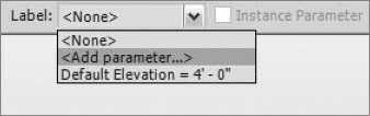
Select the dimension and use the Options bar to add a parameter (using the Label: drop-down menu) to the dimension, making it parametric (Figure 14.24).
In the Parameter Properties dialog box that opens, name the parameter Height, group it under Dimensions, make it an instance parameter, and click OK.
Now, reselect the top face of the box and drag it up and down. Note how the parameter updates with the direct edit. You'll notice that dragging a face results in overly sensitive precise dimension values — numbers that round to nearest 256th of an inch, for example. To overcome this, simply open the Family Types dialog box by clicking the Types button on the Ribbon and set the value using the properties dialog box (Figure 14.25).

Open a new project by clicking the Application button and selecting New → Project. This will open a blank project. Press Ctrl+Tab to go back to the box you were making.

Click to place the mass family, and then press the Esc key twice to cancel the placement mode.
Using the 3D view tool on the Quick Access toolbar, open the default 3D view to see the placed mass. Change the view display to Shaded with Edges, and you'll see a semitransparent box.
Select the mass and open the Instance Properties dialog box. Change the Height value to 200′ and click OK — you'll see the form update to the new height. Your mass box is now working parametrically (Figure 14.27).


You probably noticed that the material in the previous exercise appeared slightly transparent. This is because the material in the project has the same name as in the conceptual mass template, and materials in the project always trump those in the Family Editor. The reason for the semitransparent material is so you can visualize mass floors when they are added to a massing form, as shown in Figure 14.28. To add mass floor to the mass, first make new levels in an elevation view; then select the mass and use the Mass Floors command to select the levels you want to intersect the mass and to generate mass floor elements.

A revolve form takes curves and revolves them around an axis. To make a revolve, first draw a line for the axis and lines to revolve around that axis. Then select the lines and use the Create Form command. Revolves can be made from open or closed profiles:
Create a new conceptual mass family.
In the view, draw a single straight-line segment; this will become the axis of rotation.
Draw an arc offset from the line segment; this is what will revolve around the axis.
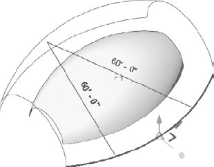
Select the arc and line, and then click the Create Form button. You will see a preview to two possible forms appear below the form: a revolve and a surface. Hover your cursor over the revolve preview and click on it; this will create a revolved form (Figure 14.29).
Select the top face of the form and open the Instance Properties dialog box. Change the End Angle value to 180, and click OK. This will give you a half-revolve form (Figure 14.30).
Select any edge of the form and experiment with dragging the control arrows (Figure 14.31). You'll notice that the start and end parameters update as you manipulate the form.


A lofted form is a surface or solid that blends between two or more open or closed curves. For example, if you draw a series of splines on different levels, you can loft between the lines and create a surface. Likewise, you can loft between closed loops, and even from a closed loop to a single line segment. Figure 14.32 shows a tower shape that is a loft between three profile loops.

Once a form has been generated, it is often necessary to divide the form into regular intervals to better understand how a complex surface can be rationalized into buildable form (Figure 14.34). Now that the surface has been divided, you can begin to place real building components on it. These components begin to suggest an architectural articulation that goes beyond mere massing studies, suggesting opening fenestration patterns, surface modulation, and surface variations.

The default setting divides the surface evenly into 12 divisions in both U and V directions. U and V represent a way to show a surface as a mesh that follows the natural contours of a surface. You are probably familiar with XYZ coordinates — U and V are simply the letters in the alphabet directly before that. Start with a simple box, and select a surface to divide; then click the Divide Surface button, and you will see the surface disappear and a UV grid appear. You can see a UV division on nonplanar surfaces in Figure 14.35.
You can change the UV division of the surface in a number of ways: using the Options bar, using instance properties, or using the Configure UV layout mode (accessible by clicking the icon that appears on the center of a divided surface when selected, as shown in Figure 14.36).


Divisions can be established using a fixed number or a fixed distance. If you want to start dividing a surface using more concrete sizes, change your division to fixed values. To change the division to use fixed distances, use the Options bar (Figure 14.37).

Once a surface has been divided, you can then apply patterns to the surface. Revit ships with a fixed set of predefined patterns that range from simple rectangles and triangles, to more complex hex patterns and brick layouts. To apply a pattern, select the divided surface and use the Type Selector (Figure 14.38).

Figure 14.38. Use the patterns in the Type Selector to create some interesting surface rationalizations
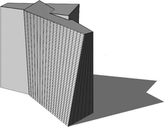
These patterns are 2D by default, but can be made 3D very easily. Once you have a 3D pattern family, you simply load it into the massing family, and it will be available in the Type Selector when you select any divided surface. Keep in mind that a surface has four levels of representation: the original surface, the UV division of the surface, a pattern that is "stitched" onto the UV division, and components that can fill in a pattern. Figure 14.39 shows the progression, from left to right. The most important thing to keep in mind is that a pattern is always made of straight segments that span from node to node along a surface — it is not made of segments that follow the curvature of a surface. This fact is important, as this is what truly makes a surface rational, and eventually buildable. Once you load a mass with curtain panels into a project, you will be able to schedule the panels as curtain panels, to get accurate counts of the panels.

Once you've made your form, you can start to skin it with Revit elements. With the Model by Face tools, you can use the mass as a basis for actual building elements and move to the next stage of design development. The tools for placing mass floors, roofs, curtain systems, walls, and floors are in the Model by Face drop-down on the Conceptual Mass panel on the Massing & Site tab (Figure 14.40)
The tool for slicing masses into horizontal planes for floor area analysis is the Mass Floors tool, which is available when you select a mass instance in the project environment (Figure 14.41).

Depending on the type of building you're making, the code regulations, and the building's functional usage, you may be ready to begin to lay out levels for the building. Imagine the maximum allowed regulated height for your building is 70′ (22 m), and your building is a hotel, which will usually have a 10′ (3 m) floor-to-floor height. In that case, you can get approximately seven levels.
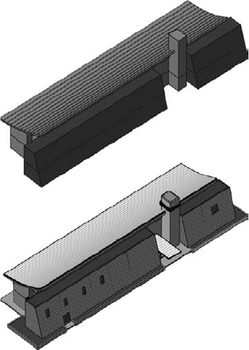
Switching to any elevation view, and using the Level tool, you can start adding levels to your project. Once you have established the number of levels your building will have, select the mass and click the Mass Floor button on the Modify Mass tab. (Note that mass floors are applied on a per-instance basis.) When you click the Mass Floor button, a dialog box will appear with a list of all available levels in the project. Clicking the levels will apply a mass floor to each level, which can then be calculated for area. Figure 14.42 shows mass floors applied to only one mass: the main building.
The slicing of masses done by the Mass Floors tool doesn't just visually help you understand the number of floors and divisions — it also provides numerical information essential for early conceptual analysis. With the help of this tool, you can find out the following:
Floor area
Exterior surface area
Floor perimeter
Floor volume
Usage

This data can help you easily create a conceptual analysis and validate the program fit. By using Revit's scheduling, sorting, and filtering tools, you can find out the exterior skin material for each use on each floor and calculate its percentage against the entire exterior surface of the building. You can do similar calculations for the floor area to determine the total use of various functions and their percentage of the total usable area of the building.
You can schedule the parameters and values of the masses as you can any other Revit element. In the earliest phase of the project, you'll probably want to schedule the functional zones. To create an understandable schedule, it's a good idea to give the mass elements you created names according to their function — Hotel, Conference Hall, Parking, Restaurants, and so on — and assign them different colors (materials) so it's easy to visually represent the data. If you need to rename the mass element once it is created, you can do that from the Project Browser — find the mass element in question and rename it using the right-click menu. You can also add project parameters to the mass elements, such as Public or Private Space, Department, and so on. If you wish to tag those new parameters so that they are shown in the mass tag, you must make them shared parameters and add them to the Massing Tag family. Out of the box, the Massing category in Revit can report the following numeric properties:
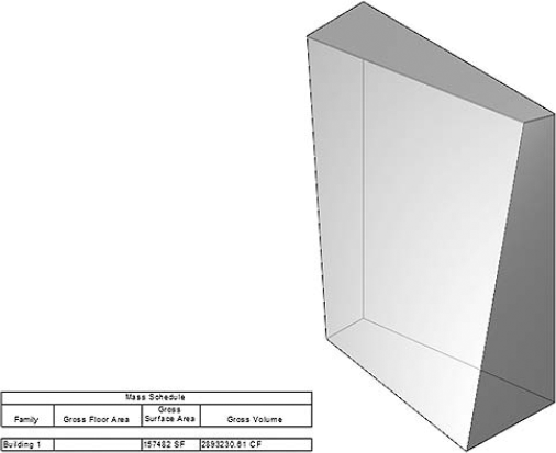
Figure 14.43. Example of a mass element without mass floors applied (no floor area faces generated as of yet)
If you create an initial mass study and schedule the mass elements, the schedule reports gross surface and gross volume of the entire shape, as shown in Figure 14.43. Note that the gross floor area is blank. The reason for that is that you can't schedule the gross floor area without first adding levels and creating mass floors, as explained at the beginning of the chapter.
When you define levels and create floor area faces using the Mass Floor tool, the floor area slices will show in the mass and the missing information about the gross floor area will be automatically filled in the schedule (Figure 14.44).

The gross floor area of the mass is the sum of all the mass floor slices belonging to that one mass element. Periodically, you need to get separate data about the floor area per floor, sorted and grouped by use or function. This is possible by creating a schedule for the Mass Floor category (Figure 14.45).

Figure 14.45. Scheduling new parameters can help you make a more accurate conceptual analysis about the use of space and materials
The reported values are useful for further conceptual analysis: you can apply different cost factors for different exterior skins. For example, you can get a good idea about how much more expensive it would be to make the last five floors of your building glass skin versus having them all be solid walls.
After you've reviewed a couple of design options with the client, a decision is made and you need to get started on the real project. Moving to the next stage is simple, because you can convert the mass into building components using specially designed tools. Let's look at these tools now.
You can start using the mass to generate real building elements such as a wall. For that you will use the Model by Face → Wall tool on the Massing & Site tab. Note that you can only create walls by face on vertical and inclined faces or arc faces of a mass. Walls cannot be applied to horizontal faces. Use Exterior Face if you modeled the massing to the exterior envelope of construction. Keep these limitations in mind:
Any wall in Revit can be converted into a curtain wall. Unfortunately, this isn't the case with walls created with the Wall by Face option. To make curtain walls, you need to use the Curtain System tool in the Model by Face drop-down list.
You can't edit the profile of a wall by face (using the Edit Profile tool available to standard walls) — meaning you will not be able to freely carve out shapes from a wall. To do that, you must change the shape of the underlying mass first.
Once you have applied mass floors to a massing, you can apply real floor elements. Choose Model by Face → Floor and start selecting the Mass floor area faces to which you want to assign a floor. To create the floors, you will need to click the Create Floors button in the Ribbon, or nothing will happen.
To accommodate floor creation in a tower with many floors, for example, you can check the Select Multiple option on the Options bar. You can then begin selecting all the floor area faces to which you wish to apply floors and finish with the Create Floors tool.
The Mass Floor tool slices the mass horizontally, creating horizontal floor plates by default.
Roofs follow the same creation principles, in that once a roof is created using the Model by Face: Roof method, you can't edit its sketch to change its shape in plan. If you created a roof by face and need to change its sketch, you must change the shape of the underlying mass from which the roof has been derived.
Curtain systems are a handy tool for dividing a façade into regular intervals of panels and mullions. With one click, you can convert the face of a mass into a curtain system with predefined parameters to match your needs. Curtain systems can be applied to any face and are composed of grids, panels, and mullions. Make sure the curtain system type you choose has a predefined Curtain Grid layout. Figure 14.46 shows a massing model with wall, roofs, curtain system, and floors applied directly to massing faces.