
There is no exact terminology used in the game industry for objects that move. It generally just comes down to the art lead asking an artist, "Hey, can you animate this?" So for the sake of this chapter, I'll just refer to such objects as movers. Movers are just like any other object and they are created using the same methods. The main difference is that movers are bound with a skeleton and, obviously, animated so that they move. In this chapter, you'll create a simple mover and go through the process of rigging and animating it.
Not too long ago, back when 3D was still relatively new in the game industry, animation was rather expensive. There were only so many moving parts that could be rendered per frame, and these were usually maximized by spending them on the characters and enemies rather than on the environment. The original Resident Evil is a good example of this. It used prerendered backgrounds to achieve its level of environment detail because real-time graphics just weren't up to snuff back then. The downside of prerendered graphics, however, is that they don't move. They're static. It's like a photograph with 3D characters running around on top of it.
Another example is the popular Final Fantasy VII, the first 3D game in the Final Fantasy series. At the time it was revolutionary, but if you were to look at it with today's standards in mind, you may notice that the characters are all made out of separate pieces, almost like action figures or Lego people.
Today, game engines are very robust and capable of doing things barely imaginable by the designers of the first generation of 3D games. And the benefit to the environment artist is that, finally, a game's locale can have just as much interesting movement as the characters that inhabit it. Switches can be flipped, doors can open and shut (without switching to a loading screen!), and miscellaneous background machines can actually look as if they are doing something suitably mechanical.
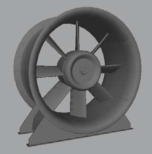
For this chapter, you'll create an industrial fan. Industrial fans are a staple of the factory environment and easily add a lot of movement to a scene. Having some rusty contraption spinning slowly in the background with suitably grating sound effects can add a lot to making a scary scene that much creepier. Or in a more functional environment, it can make a scene seem as if it is actually working and that something is happening behind the walls, even if the player can't actually see it.
Note
Before starting, make sure you set your project to your project directory by going to File → Project → Set.
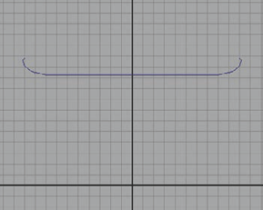
Start by going to the Side view and creating an elongated U-shaped curve about 10 units high in the y-axis, as shown in Figure 7.1.
Select it and, under the Surfaces menu set, select Surfaces → Revolve → Options. Make sure the output of the Revolve command is polygons, as it has been in other projects in this book, and choose Z as the Axis Preset. This will make the z-axis the axis used to revolve the curve. Press the Revolve button.
You should then get a circular, spool-like shape. This will be the beginning of the fan's circular housing.
Increase the V Number value under the nurbsTessellate1 Input node (found in the Channel Box) to 3 or 4 to make the shape's roundness smoother.
Select the entire shape and return to the Polygons menu set. Apply an Extrude command from the Edit Mesh menu and extrude the shape outward slightly, about 0.17 units—just to give it a bit of a lip on the edge and some thickness.
You can adjust the shape's edge loops to get a shape that's pleasing to you. Mine turned out like Figure 7.2.
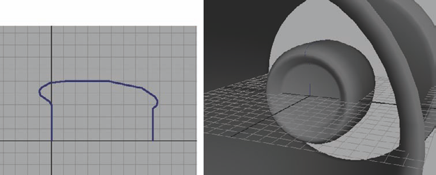
For the center of the fan, you'll use the Revolve function once again. Create a curve in the Side view that looks something like Figure 7.3. This will be the start of the fan's motor.
Once revolved, place it in the center of the fan housing. Select the front face and, using a couple of simple Extrudes and Bevels, bring out a central detail to serve as an axis, such as my example shown in Figure 7.4. You can add more details, such as bolts or screws, to your own preference.
The next step is to create the fan blades. Create a cube that is about 1 unit wide, 7 units tall, and about 6.5 units deep. Increase the cube's Subdivisions Height to 5 and Subdivisions Depth to 2, giving it a single division in the middle of the wide side of the cube.
You want the blade to be shaped like the blade of an airplane propeller—curved with a slight twist to make the circulation of air pull in a certain direction.
Select the outer vertical edge loops and scale them inward slightly, tapering the ends like you see in Figure 7.5. Once they've been tapered, bevel them with a slight rounded edge.
Now select the middle vertical edge loop and bevel it, which gives you two edge loops in the middle of the blade to work with. Scale them inward to your own preference, making the bulged center of the blade curve out a bit more gradually.
Once you have the blade shaped to your liking, you can add more details such as divots or screws and bolts. I used a few Difference Boolean operations to carve some divots into my blade.
It's time to do the twist! There are two major lines of thought when it comes to something like this—accuracy and dynamism. It'll be up to your individual project director to determine the project's preference for you. Some people want to ensure that everything is done to the utmost accuracy. Others just want the fan to look cool! Keep your own preference in mind when doing the twist in the next step. You can twist the fan blade to look accurate, or you can just make it look cool to you. Sometimes, accuracy does look cool, so don't rule accuracy out completely if cool is the look you are going for.
In either case, select the fan blade geometry, switch to the Animation menu set, and select Create Deformers → Nonlinear → Twist. A Twist deformer will be applied to your mesh.
In the twist1 Inputs (in the Channel Box) you have several settings for your Twist deformer. Adjust these to your liking and style. I ended up with a more realistic twist using a Start Angle value of 13.75 and an End Angle value of 24. You may also need to rotate your fan blade geometry if you're having trouble getting the exact look you want.
When you have the fan blade geometry completed, duplicate and rotate several fan blades around the motor like in Figure 7.6. If you need to, you can adjust the size of the fan housing to make the fan more proportional now that you have a better idea of the size of your fan.
Just as you did with the axis detail in the front of the motor, you can create an exhaust port in the back of the motor. For this detail, I went with a more "make it look cool" attitude instead of strict accuracy. It's more fun that way! By just using a series of simple Extrudes and Bevels, I came up with Figure 7.7. You are free to do whatever detail looks good to you.
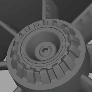
You can continue to detail your industrial fan however you see fit. I added some bolts along the outer rim of the fan housing as well as an array of indentions along the rim of the exhaust port to add a little bit of visual interest (using the Extrude command). You can see what I created in Figure 7.8.


Next, you can add a base to the fan to ground it to the floor, although sometimes these types of fans are suspended in the air or embedded into a wall system.
Create a thin, trapezoidal cube that intersects the base of the fan, as in Figure 7.9.
Duplicate it for the opposite side. Duplicate it a third time and scale it thicker to fill in the area between the two outer cubes. Shrink its width so that it's not as wide as the outer cubes of the frame.
Insert an edge loop in the middle of the center cube and scale it wider, matching the width of the cube's widest point. Lift it up slightly so that it's off the floor line. You should have something similar to Figure 7.10.
In the Front view, create a large cylinder that matches the size of the industrial fan housing's opening. Scale it out so that it extends beyond the width of the base shapes. This will be the negative-space object that you use to carve out the unwanted sections of the base.
Duplicate the large cylinder twice, giving you a total of three. In turn, use the cylinders to carve out the unwanted space of each of the three meshes that make up the base using the Difference Boolean command. When you're done, it should look like Figure 7.11.
Bevel the outer edges of the base shapes to round their corners. You can also add two thin cubes below the two outer shapes to serve as supports, as in Figure 7.12.


Now that you've finished the high-resolution mesh, you can begin to create the low-resolution mesh. Just as you have done in previous projects, you'll be duplicating the meshes and expanding the duplicates to encompass the higher detailed models.
Create a new layer in the Layer Bar and name it
Hi. Assign all of your high-resolution meshes to it.Create a new layer and name it
Lo. As you begin to create your low-resolution meshes, assign them to this layer.
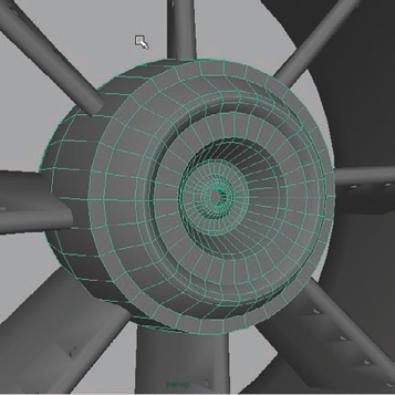
As with the other projects in this book, the main goal is to create low-resolution meshes for each unique piece of the model. This would include the base, the housing, the motor, and one of the fan blades (Figure 7.13).
With the low-resolution meshes created and assigned to their own layer, it's time for UV mapping in preparation for texturing.
Select the outer ring of faces on the housing and apply a Cylindrical UV Map from the Create UVs menu. If yours is anything like mine, you'll probably need to rotate the mapping gizmo to correspond with the shape of the fan housing.
You can do this by clicking the red hash mark on the corner of the mapping manipulator to activate the gizmo. The UV mapping manipulator gizmo is just like the gizmo used when extruding. By clicking the blue outer circle, it will toggle the cardinal direction manipulators, which will allow you to rotate the manipulator more easily. Rotate it to fit the shape (usually 90 degrees).
In the UV Texture Editor (from the Window menu) you can see the UV shell that resulted from the cylindrical UV map. Reposition it to get it out of the way.
Select the rest of the housing's faces and perform another Cylindrical UV Map on the rest. Reposition the resulting shell in the UV Editor.
Continue to unwrap the UVs for the rest of the meshes using the techniques learned in the previous UV mapping sections of this book.
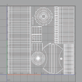
Once you have the UV shells in the UV Texture Editor, you can reposition them within the 0–1 space in the upper-right square of the editor's grid (Figure 7.14).
Note
Since we've now gone over this process six times in the last six chapters, I think it's safe to skip a little ahead. If you feel you need the rest of the process presented step-by-step, you can refer to the video reference included on the DVD.
Now that you have the low-resolution meshes, use the Transfer Maps command to bake 1024×1024 AO and normal maps for texture sources. You can also lower the resolution of the mesh further, deleting every other edge loop, but being careful to maintain your UV shell border edges. You should then have something similar to Figure 7.15.
With your source textures baked, you can go into Photoshop and complete the texturing process, finishing your diffuse, normal, and specular maps.
In Photoshop, open your AO source image. Double-click its Background layer and click OK on the dialog window that opens, which converts it into a normal, editable layer. Rename the layer
AO.If you have some areas on the AO map that you don't want in your final, take some time to clean those areas up.
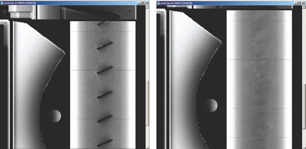
For instance, in mine, you can see where each fan blade was near the fan housing along the interior of the housing mesh due to the black, shadowy lines that were created there.
Using the Clone Stamp tool, you can fix these areas relatively easily. With the Clone Stamp tool active, hold down the Alt key and click in an area that you want to pull pixel details from. Let go of Alt and start clicking to brush down copies of those original pixels in a new location. You can see the result of this action in Figure 7.16.
The same can be done with the baked normal map. You may occasionally see areas that look strange and could require some manual cleanup.
In Figure 7.17, you can see the odd shading around the divots I carved into the fan blades. By using the Color Picker tool to pick out the color of the background, I just used my regular brush to paint around the holes, isolating them and removing the odd shading.
Once your cleanup is completed, you can start working on your diffuse texture. The texture for this fan is actually pretty simple. It'll be a silver-white metal look, mostly pretty clean, with some grunge here and there. Of course, you can texture your fan however you prefer.
Open up a good metal texture (such as the Alumox.jpg image I've included on the DVD) and drag it into your AO file. If you need to, copy the metal image around to fill up your image and drag its layer to be below the AO layer. Set the AO layer's Blending Mode to Multiply, allowing the dark pixels of the AO map to be seen over the metal image.
Adjust the levels of your metal image to make it a bright colored metal—something like what you see in Figure 7.18.
Create two Hue/Saturation adjustment layers above your metal layer. In the first, lower its Brightness value down so that the image is much darker. Fill the layer mask (the white box next to the layer thumbnail) with black to hide the adjustment layer's effects. Then, take a white brush and start painting in the shadows.
Shadows belong in places like in the middle of divots, inside the exhaust port, the underside of the frame and housing, and the interior of the housing as well.
In the second Hue/Saturation adjustment layer, increase the Brightness value, making the image much brighter, but again, hiding the effect by filling its layer mask with black.
Then, with a white brush, paint in the highlights—the raised areas, the corners, the lips of metal plates, and so on. Continue to add highlights, shadows, and other details that you desire. Before too long, you should have something like Figure 7.19.
Since, in my example, I don't want the surface of the fan to be too pockmarked, I'm going to leave my baked normal map alone, as I like the clean look it gives. Of course, you can continue to edit yours however you like to achieve the look you are going for.
For creating the specular map, you don't want to get too complicated with something that is made of the same material throughout. But you'll also want something that has relatively high contrast so that when the light hits the surface, it'll really pop out! To achieve this, hide all of your layers except the metal layer.
Select all (Ctrl+A), copy (Ctrl+C), create a new layer above all the rest, and paste (Ctrl+V). This pastes a copy of your metal layer so that you can make adjustments to it without affecting your original.
Simply adjust the levels (Ctrl+L) of the image until you have a high-contrast version of the metal, such as what I have in Figure 7.20.
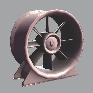
With your diffuse, normal, and specular maps all put together, you get your final result! Mine turned out as you see in Figure 7.21.


You're walking through a factory after hours. All of the workers are gone. You've tracked a serial killer to this location, and it's all up to you and your wits to find and put an end to the Curtain Call Killer once and for all! The only sound you hear is your own heartbeat and the constant churn of the industrial fans in the background.
Sounds like an exciting game! Adding even simple background movements (along with accompanying sound effects) can add a lot to an environment's ambiance and mood. It can also serve to tell little stories or give gameplay hints. What if, in our fictional detective game, the player notices that among all the fans in the factory, one has stopped turning near a long dark tunnel leading into blackness. Perhaps the killer has escaped that way? Giving level designers these types of options can give you a lot more input into a game's design than you might otherwise think.
But I digress. Let's make a looping animation for the industrial fan! It really depends on your game engine as to how animations are extracted from Maya and imported into the game itself. Some engines just allow you to animate normally and export them directly. Others may require that you animate things within the engine's specific editor. For this project, you'll just be using Maya to create the animation.
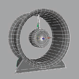
Switch to the Animation menu set, where all of your animation controls are. In the Front view, create a joint at the center of the fan. If you've been following along with me, that will be the origin of the scene and should be easy to grid-snap (hold X) to.
Press Enter after placing the joint. Rename the joint
Root.Select the fan blades, Shift-select the Root joint, and select Skin → Bind Skin → Smooth Bind → Options.
In the options, there are several different settings and values. The main one you'll be looking at is the Bind To setting. Choose Selected Joints for the Bind To setting and click Apply.
By choosing Selected Joints for your binding setting, it will bind the entire mesh to the Root joint. Since we only have one joint, it's not too big of a deal, but if you had an entire skeleton and you wanted the fan blades to only be bound to one joint, without any influence from another, choosing the Selected Joints setting would ensure that.
Now that the fan blades are bound to the Root joint, you can begin setting keys. Before doing that, though, you need to make sure you are set to the correct fps (frames-per-second). Different kinds of animations require different fps settings. For instance, films run at 24 fps. Video games run at 30 fps.
Select Window → Settings/Preferences → Preferences (or click the Animation Preferences button at the far right of the Range slider). If your Playback Speed setting is at 30, you have the correct fps setting.
If not, click the Settings section on the left side of the Preferences window and change the Time setting to NTSC (30 fps). This should change the Playback Speed to 30 as well.
Go to Frame 1 in the Time slider. Select the Root joint and press Shift+E to set a key for its rotation channels (you'll see the rotation channels highlight orange in the Channel Box). In the Time slider, at Frame 1, a red hash mark will appear. This indicates a keyframe has been set.
Figure out how fast you want the fan to spin. I set mine to go at a rather slow pace. If you'd like to follow along, go to Frame 90 in the Time slider. Select the Root joint and, in the Channel Box, change the Rotate Z value to 356. This will spin the fan blades entirely around, minus 1 degree.
You only spin it 356 degrees (and not a full 360) so that the first and last frames of your animation are not identical. If they were identical, you'd notice a small jerk as you run into two frames where the fan appears to stop. By using 356 degrees, the motion appears continuous when it loops.
Open the Graph Editor by selecting Window → Animation Editors → Graph Editor. Within this window, select the animation curves of the Root joint (make sure it's selected).
In the editor's menus, select Curves → Pre Infinity → Cycle. Then select Curves → Post Infinity → Cycle. These two options will make your animation loop continuously. Press Play!
Background animation is becoming more and more possible thanks to the advancements in game technology. Flowing grass, working machinery, waterfalls, and rumbling earthquakes are all possible now. But moving objects still require the hands of an artist to make the effect seamless within the game's world. To have a game character stand still and yet still have compelling visuals on the screen is the goal of the environment artist. Movement can make a game's world come alive so that it's no longer just a level, but rather a place!
