
Chapter 4. Understanding the service application model
In this chapter, you will learn about:
Microsoft introduced the existing service application architecture with the SharePoint 2010 product. It solved many of the key issues that were present with the SharePoint Service Providers (SSPs) from the Microsoft Office SharePoint Server 2007 (MOSS) product. Those of you who are familiar with how it worked in 2010 will find that the architecture has remained intact. With the release of SharePoint 2013, some of the services have changed, but the overall plumbing works just as it did— both the good and the bad. This chapter will explore the overall service application architecture.
To fully understand how the SharePoint service application model works, you will need to understand the core components of the services. In the next section, you will get a detailed breakdown of how services work and how they work together.
While many of the services remain unchanged, some have been rebuilt from the ground up, and others are completely new. As you review the service applications that are available in SharePoint 2013, you will gain an understanding of what these services do and some design considerations for each. One of the major changes in the product is how Office Web Applications (OWA) is installed and interacts with the SharePoint farm, and this change will be discussed in the Examining the changes in OWA section later in this chapter.
Finally, you will learn about cross-farm services or service federation. With the architectures of SharePoint broadening into multiple farms, some organizations will find it useful to have service farms that support a number of SharePoint implementations.
You will then close out the chapter by putting all of the concepts together and building a cross-farm environment that federates the Business Data Connectivity (BDC) service.
Exploring the service application architecture
The service application architecture “plumbing” is basically the same as in SharePoint 2010. Microsoft did introduce some new service applications, and even managed to remove several, but with SharePoint 2013, the service application models are relatively unchanged from SharePoint 2010. Microsoft removed the Web Analytics, Work Viewing, and PowerPoint Viewing services.
Key concepts
The term service application has been overused. This makes it difficult for people to understand where the components live and how they function. To really get a handle on what’s happening behind the scenes, it’s important to know these terms:
Service. The application binaries deployed to the servers in the farm.
Service machine instance. The actual instance of the service running on the server. The service instance also has a Log On As account associated with the instance.
Service application. The logical component that contains the service configuration and management, such as the service application configuration information and the database connection string.
Service application proxy. The interface used by the service consumers for communicating with the service and the load balancer. The proxy is required so that the consumer knows which server to contact and how to consume the actual service. It’s important to note that the service application proxy is not a web service or Windows Communication Foundation (WCF) proxy.
Service consumer. Any application or service that consumes the service. If you are using the service application, you are a service consumer.
Service proxy groups. Groups of service applications associated to specific web applications.
You can deploy services in a number of ways, including the Configuration Wizard, Central Administration, or Windows PowerShell. The Configuration Wizard will configure many of the services with their default values. You shouldn’t use this for production environments, as there are many services that should be manually configured to ensure success.
In Central Administration, you can configure several services by populating fields associated with them. While you have a little more control than with the Farm Configuration Wizard, most SharePoint professionals will opt to use Windows PowerShell.
Windows PowerShell gives you the most control over the deployment of your service applications into your environment. The provisioning of some of the service applications can be very tricky, but you can still provision them all through Windows PowerShell.
When you configure your SharePoint farms, you get two services created automatically. These are key components for how the services work. These services include:
The Application Discovery and Load Balancer service application
The Security Token service (STS) application
Service applications must expose a web endpoint because all of their communications take place over HTTPS. It’s also important to know that service applications communicate over TCP ports 32843 (HTTP) and 32844 (HTTPS).
Service applications are consumed by web applications, and each web application can have a specific set of proxy groups assigned to it. In Figure 4-1, you can see that the default proxy group and the secondary proxy group are getting consumed by different web applications and are sharing four service applications.

Having the ability to pick and choose which proxy groups are assigned to which web application allows you to easily create a service architecture that is as complicated as you require.
Discovering the service application components
Now that you know some of the key terms associated with service applications for SharePoint, let’s take a look at what components make up a service application:
Service application endpoint
Service application proxy
Service application implementation
Database(s)— which are optional
Service application endpoint using the WCF framework
The WCF is a communications framework for sending asynchronous messages between endpoints hosted by Microsoft Internet Information Services (IIS) or hosted within an application such as SharePoint. So when SharePoint services communicate between servers, they use the WCF framework. The complexity of the messages sent over WCF depends on the service using the framework; for example, a message might be as simple as a piece of XML data or as complex as a stream of binary data.
Service application proxies
You can assign a specific service application to an individual web application. The web application uses the service application proxy as a way to connect to the service application because the consuming web application does not talk directly to the service application. You also have the ability to assign a single proxy to multiple proxy groups; however, you are not able to create custom-named proxy groups through Central Administration. To create your new friendly named proxy group, you will have to use the following Windows PowerShell cmdlet, where “Group Name” is the name of the proxy group that you wish to create.
PS C:> New-SPServiceApplicationProxyGroup "Group Name"
After the new proxy group has been created, users can add service applications to the group through the Central Administration graphical user interface (GUI) or through Windows PowerShell using the Add-SPServiceApplicationProxyGroupMember cmdlet. In Figure 4-2, you can see that a custom Application Proxy Group called Staff has been created for the Staff web application.

By clicking the name (Staff) of the application proxy group, you are able to assign the application proxies (shown in Figure 4-3).

Service application implementation
Users have the ability to implement out-of-the-box service applications either through the Central Administration GUI (Development Environment) or through the use of Windows PowerShell; meanwhile, the creation of custom service applications is done through a deployment package. The implementation of service applications can be in dedicated application pools and can be run by different service accounts. When deploying, you can adjust settings or can customize settings after the service application has been implemented. Users have the ability to modify service application proxies through either the administration user interface or through Windows PowerShell.
Database(s) and service applications
A database for a service application is not a requirement; however, for service applications, such as the Search service or the User Profile service, the service application could require more than one database, or for service applications, such as the Microsoft Visio Graphics service or Microsoft Excel, the service might not require any databases. Also, service applications do not need to be implemented as a WCF service. If you deploy your service applications using the Farm Configuration Wizard (into your development environment farm), the database names are automatically created with the service application name, as well as with a GUID. However, when you deploy your service applications into your production environment using Windows PowerShell, you can create user-friendly database names that follow the database naming convention of your organization.
Examining the changes in OWA
The final product that is exposed to the user from the new OWA server is essentially the same as the OWA for SharePoint 2010. They both allow users to view and potentially edit browser-based versions of Microsoft Word, Microsoft PowerPoint, Microsoft Excel, and Microsoft OneNote files. In SharePoint 2010, OWA is a tightly integrated product that must be installed on every SharePoint server in your SharePoint 2010 farm, and it only worked with SharePoint (see Figure 4-4).

For SharePoint 2013, OWA is now a stand-alone server product, which can be downloaded from http://tinyurl.com/PCfromDC-OWA. The new OWA server gives you the ability to scale out and create an entire OWA farm. It also gives you the ability to integrate OWA into other products outside SharePoint. The OWA server works with products and services that support the Web App Open Platform Interface (WOPI) protocol. The new OWA server farm can support accessing files through Microsoft Lync Server 2013, Microsoft Exchange Server 2013, shared folders, and other websites besides SharePoint (Figure 4-5). The OWA server can be installed on one or more physical or virtual server and is free to use as a document viewer (read-only).

How does it work?
There are not a lot of steps in the process of how OWA functions within SharePoint 2013 (see Figure 4-6).

As you can see in Figure 4-6, there are four steps required to get a document to view within a web browser using the SharePoint 2013 OWA server:
The user requests to edit a Word document from a SharePoint library (GET method), and SharePoint returns an IFrame (WopiFrame.aspx) with information that will be used to redirect to the WOPI server and negotiate the access tokens that OWA will use for the rest of the user session.
POST to WOPI server to populate a new wordviewerframe.aspx IFrame.
The WOPI App contacts the WOPI Host to GET the document.
The WOPI App renders the document in the IFrame and loads a few CSS files, several JavaScript libraries, and the OneNote.ashx web handler. After page load, the OneNote.ashx web handler will POST for approximately 15 seconds.
Examining the changes in workflows
Workflow for SharePoint 2013 continues the theme of breaking out SharePoint 2010 services. The 2010 workflow service is still available in SharePoint 2013 to maintain interoperability post upgrade, but to run a SharePoint 2013 workflow, you must install Workflow Manager (http://tinyurl.com/PCfromDC-WAWS). In fact, when creating a workflow in SharePoint 2013, you are only given the ability to create SharePoint 2010 (Figure 4-7) workflows until your SharePoint 2013 farm is bound to the Windows Azure Workflow Server (WAWS).

By breaking workflow into its own server, WAWS has become a great example of the new SharePoint application model. Workflow communications happen via the core app model technologies, CSOM and REST, and authenticates through OAuth. Like the OWA server, WAWS can run on its own farm, be used to handle workflows for more than one server farm, and work with more than one type of technology (see Figure 4-8). For example, you can run your WAWS farm with a SharePoint 2013 farm and with a Microsoft Project 2013 server farm simultaneously.

However, unlike OWA, WAWS can be installed on SharePoint servers. Workflow traffic happens over ports 12290 (HTTPS) and 12291 (HTTP) by default. You should set up your WAWS to run over HTTPS—installing WAWS on a domain controller is not supported.
How does it work?
Figure 4-9 shows the steps required for workflow to function within SharePoint 2013.

As seen in Figure 4-9, there are several steps that are required for the successful start of a workflow:
When setting up the workflow infrastructure, server-to-server (S2S) authentication is created automatically so that OAuth can run correctly when a workflow action starts.
To maintain backward compatibility, SharePoint 2013 has the SharePoint 2010 workflow platform already installed. If you are upgrading to SharePoint 2013, then your SharePoint 2010 workflows will simply work out of the box.
When the workflow event is triggered, communications to start the workflow happen over Windows Azure Service Bus.
The information is then passed to the Azure Workflow Service to send the workflow data back to SharePoint using the REST application programming interface (API).
Discovering the new web service applications available in SharePoint 2013
One of the ways Microsoft improved the functionality of SharePoint 2013 was by improving the functionality of the service applications. As the foundation of how SharePoint operates, there have been new service applications created, improved, and removed or consumed by other service applications.
There are four brand new service applications in SharePoint 2013: the Application Management service, the SharePoint Translation service, Work Management service, and Access Services. Even though there was an Access service in SharePoint 2010, there is now an Access Services 2010 (the old service with a new name), and the new Access Services (a new service with the old name).
Access Services
The Access Services web service application is based on the same service application namesake from SharePoint 2010. Access Services allows users to host Microsoft Access databases in SharePoint 2013 after being built using the Access 2013 desktop client and published into SharePoint. The Access Services for SharePoint 2013 can view and edit the Access 2010 web databases and even republish them into SharePoint 2013. The new service does not just allow you to create a website based on an Access database, but it will create the database schema and logic within a Microsoft SQL Server 2012 instance to store the Access database tables and information. Once the Access database has been provisioned, users will be able to view, edit, and interact with the Access 2013 database through their web browser. Unlike many of the SharePoint Server 2013 application services, Access Services 2013 doesn’t expose an API that you can use to develop Access apps in Microsoft Visual Studio. Access 2013 client is the tool that you use to develop Access 2013 apps, as shown in Figure 4-10.

Because the Access Services creates SQL databases and tables to store the Access databases, there are some SQL prerequisites that must be met. You can read more about Access Services and its prerequisites on Microsoft TechNet at http://social.technet.microsoft.com/wiki/contents/articles/12514.sharepoint-2013-access-services.aspx.
How does it work?
The user is using the Access run-time host to access the data from SQL Server 2012 and creating the output in HTML. SharePoint does not create any lists or renderings when using this service. When users accesses their page, they are retrieving the data from SQL using Access Services. When you add an Access database to SharePoint 2013, you will get a brand new SQL database.
The App Management service
With the introduction of the Windows Store came the need for the creation of the Application (App) Management service. The App Management service is responsible for storing and providing the SharePoint app licenses and user permissions, which are stored in its own database. If you purchase an app from the Windows Store, the App Management service will store all of the information about downloaded app licenses. Each time a user tries to use a SharePoint app, the App Management service will query its SQL database to validate that the user has permissions to use the app and that the license is valid (see Figure 4-11).

How does it work?
The App Management proxy queries SQL to get the information about the app.
SQL returns information saying that the user and the app are valid and approved.
The administrator of the app sets permissions for who can and cannot use the app and manages the app licensing.
The Machine Translation service
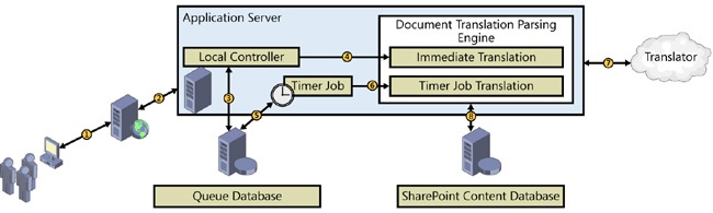
The Machine Translation service allows SharePoint to translate content from one language into another through Microsoft Translator. Translator is a cloud-based translation service, so the server that is running the translation service must have the ability to access the Internet. If your organization limits which users can access the Internet, the service account that is running the service will also need permission to access the Internet. The Machine Translation service can run synchronously or asynchronously, or it can stream the translation of documents, pages, or sites. If you are using variations, it is possible to translate pages automatically based on target labels, and Managed Metadata service terms are also included in the variation translation, as shown in Figure 4-12.
The Machine Translation service is supported as a cross-farm (federated) service, is supported over wide area network (WAN) connections, and has its own database.
How does it work?
The user accesses the content that needs to be translated from a website, such as a document on demand, or a new site that might have its translation scheduled for overnight.
The Machine Translation service proxy passes the information from the web application to the Machine Translation service.
The local controller pushes the document into the queue database.
The local controller sets the item for immediate translation or for translation using the service timer job.
Once the item is added to the document queue database, the item either waits for the timer job or it gets put at the top of the queue for immediate translation.
The item is moved from the content database to a local temp folder, where the item’s content is parsed from the document by the Document Translation Parsing Engine.
The parsed content is sent to Translator for conversion, and the document in the temp folder is updated.
Item translation is completed, and content is saved back into the content database.
The WMS application
Task aggregation across multiple platforms within an organization has been a huge thorn in the sides of many people. This new Work Management Service (WMS) gives SharePoint 2013 the ability to take all of the tasks assigned to a person from SharePoint, Exchange, Project, and custom providers and render them in a single location, as shown in Figure 4-13. The WMS is dependent upon the Search service application and the User Profile service application to be provisioned. The service account that is running your WMS application will need full control permissions on the User Profile service application.

How does it work?
The user goes to his or her My Site URL.
The WMS application proxy talks to the WMS on the application server.
The user’s tasks are displayed based on the information on the WmaAggregatorList_User hidden list.
Every 15 minutes, the service application makes a request for the user’s task changes from the providers located in the ..15CONFIGWorkManagementServiceProviders provider.sptasklist.xml file. Out of the box, only SharePoint will be available in this list, but as you add providers such as Project, the list will be updated.
The WMS application starts the timer job to return Exchange tasks.
Exchange task data is returned.
The user’s hidden WmaAggregatorList_User task list gets updated.
Discovering the updated web service applications available in SharePoint 2013
Some of the service applications were tweaked a bit, a few new services were created, and one service application had its historic functionality returned. This section will review the returning service applications that can be created in SharePoint 2013.
Access Services 2010
The Access Services 2010 web service application allows the backward compatibility of existing Access web databases from SharePoint 2010. Access Services 2010 allows users to view, edit, and interact with their Access 2010 databases through their browser. SharePoint does not store the Access Services Access databases in SQL, since this service functions the same as it did in SharePoint 2010.
The BDC service
The BDC service allows users to interact with data that does not live within SharePoint. There are out-of-the-box connectors that allow communication to external databases, such as a SQL database that contains sales data. BDC can publish the external data just like a standard SharePoint list and gives the users the ability to perform standard create, read, update, or delete (CRUD) operations on external line-of-business (LOB) systems (see Figure 4-14).
BDC is supported as a cross-farm (federated) service, is supported over WAN connections, and has its own database.

How does it work?
The one common scenario is to expose external LOB data as a SharePoint list. Another common scenario is using BCS to extend Search to index external LOB systems as well. The first step is usually to create an account used to retrieve the data before entering the credentials into the Secure Store service (SSS). The next step is to create the external SharePoint connector to the LOB data system. This is done by utilizing the built-in connectors or creating a custom connector. The returned data can be used within Search, Web Parts, and even User Profiles, and it can be viewed in a SharePoint list as well.
Excel Services
The purpose of Excel Services has not changed from SharePoint 2010. It still exists to publish Excel work sheets, workbooks, and data within a web browser. However, there have been several enhancements made to Excel Services from a developer perspective, such as updates to the REST API to request data through the Open Data Protocol (ODATA), and to the ECMAScript. There is also a new Excel Interactive View, which uses Excel services to generate Excel tables and chart views on demand, as diagrammed in Figure 4-15.

How does it work?
The purpose of the Excel Services application is to expose Excel workbooks through a web browser. This is done through the Excel Services application proxy, which uses the Excel Services application to grab the data from either a local content database or an external data source. Notice that in SharePoint 2013, you have the option to access the Excel web application proxy through REST and JavaScript. If you are running OWA on your farm, this will create a second version of Excel Services. As you can imagine, having two versions of Excel Services cannot be good. If you want the ability to view and edit Excel documents in a browser, then you will want to stick with OWA; otherwise, if you are interested in the advanced business solutions provided by Excel Services in SharePoint out of the box, then do not use OWA. Choose wisely based on your individual business case.
The MMS application
The Managed Metadata Service (MMS) application makes it possible to use managed metadata and share content types across site collections and web applications. Managed metadata is a hierarchical collection of centrally managed terms that users can define and then use as attributes for items. When you create the MMS application, a centralized term store is created to manage the keywords and terms, which gives the administrator the ability to point other web applications to the centrally managed MMS.
Another feature that is handled by the MMS is the ability to share content types. After creating the MMS and selecting a specific site collection as the content type hub location, users can share content types, such as columns, workflow associations, and policies, from their site collection’s content type gallery. It is possible to create multiple MMS and share multiple term stores and content types from multiple site collections, but the question of whether you should deploy more than one MMS would depend on your corporate information architecture. The architecture for MMS is the same as it was for SharePoint 2010.
MMS is supported as a cross-farm (federated) service, is supported over WAN connections, and has its own database.
The PPS application
The PerformancePoint Service (PPS) application allows users to create business intelligence (BI) dashboards, custom reports, filters, tabular data sources, and scorecards (see Figure 4-16). This is the tool that creates all the pretty pictures to show management a quick overview of an organization’s health. Using PPS with PowerPivot for SQL Server 2012 rounds off the BI integration stack by extending the capabilities of a user to dive deep into data. PerformancePoint alone will give you the dashboards to alert you of potential issues or trends, and PowerPivot will allow you to analyze (in detail) the source of the issue or trend.

How does it work?
The way that this application exposes data is very similar to Excel Services, except that users have the ability to interact with their data using AJAX and JSON. The proxy service uses the service application to grab the requested data, and then displays the data to the user. The PPS application does not have its own database.
The Search service application
Search is one of the major cornerstones that has made SharePoint a success. For SharePoint 2013, it can be said that the enhancements to the Search service application are not just the best upgrade of the service applications, but probably the best feature of SharePoint 2013. The integration of FAST into SharePoint 2013 Search, as well as shifting the responsibilities from the SharePoint 2010 Web Analytics Service, have made this service application one of the most important features of SharePoint. However, your SharePoint 2013 Search is not just FAST repurposed. Microsoft took the best of SharePoint 2010 Enterprise Search and combined it with the best of FAST to come up with Search for SharePoint 2013. Search is probably one of the most important services within SharePoint 2013, and it is critical to keep this service functioning at peak performance, not only for user satisfaction, but also to help SharePoint administrators keep track of what is happening on the web analytics side of SharePoint. The ability to give the site owners the flexibility to look at the analytics and adjust the search scopes accordingly should help reduce the strain on the administrative staff and make the site owners happier. The Search service application crawls content, maps the information to managed properties, updates analytics, updates the search index, handles user search queries, and displays the query results.
Search is supported as a cross-farm (federated) service and is supported over WAN connections. Search crawls over your corporate WAN to consume the content of your remote farms will eat up your network bandwidth, so plan and crawl accordingly.
How does it work?
The Search service application comprises several components and databases, as shown in Figure 4-17. Just like the other services, before implementing Search, you should take high availability and fault tolerance into account. You should also consider the volume of your content, the estimated page views, and the number of search queries that are going to happen when you architect out your Search service.
SharePoint Search has two system service instances: the SharePoint Search Host Controller and the SharePoint Server Search 15. The SharePoint Search Host Controller is responsible for performing the host deployment and management for the SharePoint Search components on a single host. In a single-server installation, the host controller will start up five Noderunner.exe processes, one for each of the following search components:
Content processing
Analytics processing
Index
Query processing
Search administration
This leaves the final component, the crawl component, to be handled by the SharePoint Server Search 15 instance.

The crawl component is responsible for crawling content—not just SharePoint content, but also network folders, webpages, Exchange, and even custom LOB applications (piped items in Figure 4-17). The crawl component is responsible for collecting the content and metadata of the crawled items. To crawl content, the crawl component (crawler) connects to the content source by using the appropriate indexing connector with the appropriate crawl account. After the content has been crawled, the crawl component passes the crawled information to the content processing component for parsing. The crawling and indexing components are now discrete components in SharePoint 2013, where they were not in SharePoint 2010.
The content processing component is responsible for processing the crawled items and sending that information to the index component. You still have the ability to use custom iFilters, which are supported through a generic iFilter handler. In SharePoint 2013, you will not have to supply a .pdf iFilter because since it is native to the content processing component. The content processing component also transforms the crawled items into objects that can be included in the search index by parsing the document and document property mappings. This component is also responsible for linguistics processing such as language detection. The content processing component also updates the Link database with information about links and URLs. This content processing component is also responsible for generating the phonetic name variations for People Search. The content processing component sends the information to the index component and updates the analytics processing component by directly modifying the Link database.
The analytics processing component analyzes the crawled items and how users interact with the search results, then updates the search analytics information stored in the Link database. The analytics processing component is also responsible for maintaining the usage analytics information. For example, when a user loads a page, the page load event information is stored in the usage files on the web server and then pushed to the event store, where the data will remain until the analytics processing component updates the information in the Analytics Reporting database.
The index component receives the processed items’ information from the content processing component and writes the information to an index file. The index files are stored on a disk in an index replica. The index component is also responsible for handling the incoming search queries, retrieving information from the query processing component, and sending the query result set back to the query processing component. You can divide the search index into separate slices, called index partitions, where each index partition holds one or more index replicas. The search index is the aggregation of all index partitions. Indexes can be scaled out both horizontally (partitions) or vertically (replicas). Replicas are created for fault tolerance and to help increase the query throughput.
The query processing component analyzes and processes the incoming search queries and results. When the query processing component receives a query, it analyzes the query for relevance to help optimize the search precision. The processed query is sent to the index component, which in turn processes that result set before returning the search results to the web server.
The search administration component is responsible for running and monitoring the system processes for the search components. The search administration component is also responsible for provisioning and topology changes. Search topology is no longer modifiable through the Central Administration GUI, only through Windows PowerShell.
In SharePoint 2013, there are now four databases for Search out of the box, as compared to three for SharePoint 2010. This should not be too much of a surprise because Search did consume the SharePoint 2010 Web Analytics service. The four databases are as follows:
The Crawl database still stores the details about crawled items. It also stores historical information, such as the last crawl time, the last crawl ID, and the type of update during the last crawl.
The Link database stores information (links) gathered by the content processing component. It also stores information about the number of times that people have clicked a search result from the search result page.
The Analytics Reporting database stores the results of usage analytics and contains the extracted information from the link database. The Analytics Reporting database will also store search reports, such as item reports, like the number of views per document over time, or site level reports, like the number of unique visitors over time. Data is aggregated to monthly views every 14 days. A portion of the data is passed to the search index component, such as different view counts.
The Search Administration database stores search configuration data and the analytics settings. The Admin database no longer stores the access control list (ACL). There can be only one Search Administration database per Search service application.
You can read more about the Search databases in Chapter 5.
SSS
The Secure Store Service from SharePoint 2010 replaced the Single Sign On (SSO) feature in MOSS. SSS is a claims-aware service that stores user names and passwords in an encrypted database. The SSS can store more than just identities and passwords; it can store custom fields as well. The SSS is generally used to store identities and passwords to access external back-end systems within an organization. Within SharePoint, SSS is used to hold the unattended service accounts for other services such as Excel, Visio, PerformancePoint, and PowerPivot services. BCS also uses SSS to store the credentials that it requires to access external LOB data systems.
Before you try to use SSS for the first time, you will need to provide an encryption (passphrase) key, which the SSS will use to encrypt and decrypt credentials stored in its database. It is a good idea to keep a copy of the passphrase in a secure location, such as an encrypted password safe, but you can force a re-encryption of the database based on a new passphrase should you lose your original SSS passphrase. If you are going to force a re-encryption of your SSS database, back it up first. The architecture for SSS is the same as it was for SharePoint 2010.
SSS is supported as a cross-farm (federated) service and is supported over WAN connections, but not recommended across WANs due to the latency created for the applications consuming it. SSS also has its own database.
UPA
The User Profile service application (UPA) stores information about users in a central location, and it can even be set up to synchronize external LOB data to enhance the users’ profile data. UPA is required to provision My Sites and enable social features such as Profiles pages, Social Tagging, and Newsfeeds. UPA is also required if you are planning on distributing user profiles across multiple farms. UPA is one service that added functionality by taking features of past deployments and integrating them into the improved SharePoint 2013 UPA. Like in the SharePoint 2007 days, there is once again the ability to run in Active Directory Import (ADI) mode.
Running in ADI mode has its limitations. Since you are not running the User Profile Synchronization (UPS) service, you will not be able to synchronize your user profiles with external data. The UPS for SharePoint 2013 (see Figure 4-18) is the same as it was for SharePoint 2010.
UPA is supported as a cross-farm (federated) service but is not supported over WAN connections. UPA has its own database.

How does it work?
As you can see from Figure 4-18, there are a lot of moving parts in the UPA. Starting with a timer job to synchronize connections to profile sources, the previous figure uses the Forefront Identity Manager (FIM) synchronization service to synchronize Active Directory (AD) to the user profiles within SharePoint. The FIM service updates the Profile and Sync databases, which are used by the UPA, and exposed to the web application through the proxy. The Social database is updated with information about social tags, notes, and ratings as users click through the farm. Having deployed UPS, users are also able to synchronize external LOB data to the user profiles. In SharePoint 2013, the Work Management service application has become dependent upon the successful installation of the UPS. If you have chosen the Active Directory Import route, the timer job for the synchronization connection starts, and the User Profile service starts a bulk import of the user profiles from Active Directory.
VGS
The Visio Graphics service (VGS) allows users to view and refresh Visio diagrams in a web browser. It is the service used to create the Visio diagrams so that you can monitor workflow progress, if enabled, and is a great tool for keeping everyone on the same page regarding how things work. VGS supports the new Visio file format .vsdx, which will allow users to save files directly into SharePoint and not publish them as Visio Web Drawings (.vdw) files. The new service will also natively render Visio macro-enabled drawing (.vsdm) files. One of the other new features within Visio 2013 is the ability to use BCS to refresh external content, tied in with the ability to use SSS for handling authentication. See Figure 4-19 for more information on the architecture of VGS.

WAS
The Word Automation service (WAS) performs bulk Word document conversions. The document conversions are automated, unattended server-side conversions. That means that you cannot convert the documents without having custom code written. The conversions can only happen with documents that are a supported “Save As” file type from within the Word client application. In SharePoint 2010, the conversion of Word documents was dependent on the timer service, which could be adjusted to convert documents every minute. In SharePoint 2013, you have the option to create a file conversion request that happens immediately (see Figure 4-20 for more information). Notice that there is a similar architectural layout as the new Machine Translation service. This is not surprising because the Machine Translation service was built using the WAS code. As with the Machine Translation service, the Word Automation service has its own database to store the document queue information.

How does it work?
The user accesses the site that has a custom Web Part that starts an automated conversion of documents from a document library. Based on the code for the Web Part, the document can be converted on demand or can be scheduled for overnight.
The WAS proxy passes the information from the web application to the WAS.
The local controller pushes the document into the queue database.
The local controller sets the item for immediate translation or for translation using the service timer job.
Once the item is added to the document queue database, the item either waits for the timer job or it gets put at the top of the queue for immediate translation.
The item is moved from the content database to a local temp folder, where the file is converted.
Item conversion is completed, and the file is saved back into the content database.
Discovering the service applications that SharePoint creates automatically
After you have thrown down the bits for SharePoint, it is time to install Central Administration. Regardless of whether Central Administration was installed via Windows PowerShell or through the SharePoint Products and Configuration Wizard, SharePoint creates a couple of critical service applications for your farm automatically.
The Application Discovery and Load Balancer service
The Application Discovery and Load Balancer service is also known as the Topology service, and as its name says, one of the functions of this service is to provide load balancing. However, it is not a network load balancer for your websites (spWebs); rather, it is a load balancer for your service applications. This is a round-robin service and is used by the service applications for load balancing and fault tolerance, which allows you to have the same service enabled on different servers for high availability.
The application discovery side of this service occurs when the service application proxy requests an endpoint for a service application from the load balancer. The load balancer maintains a list of the available endpoints for each service application in cache on the consumer and returns the next available endpoint when queried. There is also a timer job that updates the cache that runs every 15 minutes by default. You can manually start a refresh of the endpoints by running the following Windows PowerShell cmdlet:
PS C:> Start-SPTimerJob job-spconnectedserviceapplication-addressesrefresh
There is more information about service application endpoints in the Service application endpoint using the WCF framework section, earlier in this chapter.
STS
The Secure Token service (STS) is another service that is automatically created when you provision your SharePoint farm. The STS is a WCF service (.svc) endpoint that is designed to respond to requests for security tokens and provide identity management.
User authentication in SharePoint 2013
User authentication is the validation of a user’s identity against a trusted authentication provider. SharePoint 2013 uses STS to handle the claims-based authentication for user authentication. If the user is authenticated through a claims-based authentication, a claims-based security token is generated by SharePoint STS and converted into an SPUser identity (see Figure 4-21).

How does it work?
If the request is not authenticated, the user gets routed to the Authentication Selection page to use the appropriate authentication for that zone.
The request is processed by one of the authentication methods. If there is more than one type of authentication provider for the web application, the user will be given a choice of what provider to use for authentication.
The user is authenticated by the identity provider.
If authentication succeeds, STS generates a claims-based token for the user with the information provided by the identity provider. If additional claims providers are configured, the STS augments the user’s token with the claims given by the claims provider.
The claims-based token of the user is sent back to the authentication components.
The authentication components redirect the request back to the resource address, with the claims-based token issued for the user.
The response is sent back to the user. Authentication and authorization are now complete.
S2S authentication in SharePoint 2013
S2S authentication is the validation of a server’s request for resources that is based on a trust relationship established between the STS of the server that runs SharePoint 2013 and the STS of another server. For S2S authentication to work, both servers must support the OAuth server-to-server protocol. Examples of on-premises servers that support S2S authentication are SharePoint 2013, Exchange Server 2013, and Lync Server 2013. In Office 365, Azure Workflow service and SharePoint 2013 support S2S.
Because of the established trust relationship, a requesting server can access secured resources on the SharePoint 2013 server on behalf of a specified user account. For example, a server running Exchange Server 2013 can request resources of a server running SharePoint 2013 for a specific user account.
When a server running SharePoint 2013 attempts to access a resource on a server or a server attempts to access a resource on a server running SharePoint 2013, the incoming access request must be authenticated so that the server accepts the incoming access request and subsequent data. S2S authentication verifies that the server running SharePoint 2013 and the user whom it is representing are trusted.
The token that is used for a S2S authentication is a S2S token, not a logon token. The S2S token contains information about the server that requests access and the user account on whose behalf the server is acting.
Exploring service federation
During the architectural design phase of your environment, you should have reviewed the consolidation of existing farms. However, what if you cannot consolidate all of your farms? You do not want to waste server resources by replicating out the same Search service on all of your farms when you could provision a Search service farm to handle search for all of your farms. The primary reason for creating a service farm is to consolidate services into one farm and share the resources across your organization. Another reason to implement a service farm would be for the delegation of service management to different departments or groups, or even an entirely different organization. If you are going to set up a service farm that is going to be accessing other Active Directory domains, a two-way trust is required for UPA—MMS does not require a trust—and the rest of the services will work with a one-way trust. Federating your services will also give you the ability to scale out your services as your farm(s) grow. If you are thinking that you should create a service farm, remember that you need to let the business requirements dictate your decision, not the technology. Just because you can federate your services does not mean that you need to create a service farm.
In SharePoint 2013, there are six services that will federate:
BDC
Machine Translation
MMS
Search
Secure Store
UPA
There were six services that federated in SharePoint 2010 as well; however, the SharePoint 2010 Web Analytics service was consumed by the new Search service. The Machine Translation service is new to service federation with SharePoint 2013.
One advantage of using SharePoint 2013 for your cross-farm services is the ability of the service applications to be consumed by SharePoint 2010. The SharePoint 2013 services that can be consumed by SharePoint 2010 are:
BDC
MMS
Search
Secure Store
UPA
The way to create the consumption of a federated service application is the same in SharePoint 2013 as it was in SharePoint 2010. The ability to have a SharePoint 2013 services farm consumed by another farm is started by creating a trust between the two farms. While a lot of work has been done to create S2S trusts within the new SharePoint app model, creating your trust between farms is still certificate based. There are three certificates that must be used to create the trust: the SharePoint Root certificate, which signs the STS certificates; the STS certificate, which signs the claims tokens; and a Secure Sockets Layer (SSL) certificate to keep the service requests encrypted over HTTPS. The way to establish the trust between the two farms is to exchange the Root certificate between servers, and to have the publisher trust the consumer’s STS certificate, as illustrated in Figure 4-22.

Once you have set up your service farm, you can assign your default and custom application proxy groups, as shown in Figure 4-23.
The Putting it all together section of this chapter offers a demonstration on setting up BCS as a federated service, and you can review the Putting it all together section of Chapter 8, for the deployment of a federated Search farm.

Putting it all together
Now that you understand the principles and architecture behind service applications, it is time to build a service farm. In this scenario, it has been determined that Contoso needs to have a BDC service farm created to help keep business units up to speed and in sync with the corporation’s data. The first thing that will need to be accomplished is the creation of the new service farm. It is best to match version numbers between your service farm and your consumer farm.
Creating the farm trust
As previously mentioned, to create a trust between farms, an exchange of certificates needs to take place. From the consumer farm, export the Root and STS certificates. The exporting of the required certificates can only be done using Windows PowerShell:
PS C:> $rootCert = (Get-SPCertificateAuthority).RootCertificate
PS C:> $rootCert.Export("Cert") | Set-Content C:consumerFarmRoot.cer -Encoding byte
PS C:> $stsCert = (Get-SPSecurityTokenServiceConfig).LocalLoginProvider.SigningCertificate
PS C:> $stsCert.Export("Cert") | Set-Content C:consumerFarmSTS.cer -Encoding byte
The next step will be to export only the Root certificate from the service farm:
PS C:> $rootCert = (Get-SPCertificateAuthority).RootCertificate
PS C:> $rootCert.Export("Cert") | Set-Content C:servicesFarmRoot.cer -Encoding byte
After the export has completed, copy the consumer Root and STS certificates to the service farm, and copy the Root certificate from the service farm to the consumer farm. From the service farm, establish the trust by importing the Root and STS certificates:
PS C:> $trustCert = Get-PfxCertificate C:consumerFarmRoot.cer
PS C:> New-SPTrustedRootAuthority consumerFarm -Certificate $trustCert
PS C:> $stsCert = Get-PfxCertificate C:consumerFarmSTS.cer
PS C:> New-SPTrustedServiceTokenIssuer consumerFarm -Certificate $stsCert
From the consumer farm, import the Root certificate only:
PS C:> $trustCert = Get-PfxCertificate C:servicesFarmRoot.cer
PS C:> New-SPTrustedRootAuthority servicesFarmRoot -Certificate $trustCert
By taking a look within Central Administration | Security | Manage Trust on the consumer (Figure 4-24) and service farms (Figure 4-25), you can verify that you have installed the certificates correctly.


Configuring the topology service
Because the topology service maintains a list of all of the endpoints for the SharePoint farm, the consuming farm must have access to the publishing farm’s topology service. This can be achieved by taking the Farm ID from the consumer farm and giving it permissions on the Topology service application on the service farm. The following Windows PowerShell cmdlet will export the consumer farm’s ID:
PS C:> $farmID = (Get-SPFarm).Id
PS C:> New-Item C:consumerFarmID.txt -type file -force -value "$farmID"
After the file has been created, copy the file to the service farm and run the following Windows PowerShell cmdlet to give the consumer farm access to the service farm’s topology service:
PS C:> # Run the following commands on the services farm to set up the trust relationship with
the consumer farm:
PS C:> $farmID = Get-Content c:consumerFarmID.txt
PS C:> $security = Get-SPTopologyServiceApplication | Get-SPServiceApplicationSecurity
PS C:> $claimProvider = (Get-SPClaimProvider System).ClaimProvider
PS C:> $principal = New-SPClaimsPrincipal -ClaimType "http://schemas.microsoft.com/
sharepoint/2009/08/claims/farmid" -ClaimProvider $claimProvider -ClaimValue $farmID
PS C:> Grant-SPObjectSecurity -Identity $security -Principal $principal -Rights "Full Control"
PS C:> Get-SPTopologyServiceApplication |
PS C:> Set-SPServiceApplicationSecurity -ObjectSecurity $security
The creation of the permission set can be verified by going into Central Administration of the service farm and looking at the permissions for the Application Discover and Load Balancing service application, as shown in Figure 4-26.
Publishing your service application
The first step toward being able to publish your service applications is provisioning your service applications. If you have not provisioned the service applications that you wish to publish, you will need to do that first. After you have provisioned the BDC service application and proxy on your services farm, publish the service application by going into Central Administration | Application Management | Manage Service Applications | Business Data Connectivity Service Application | Publish (in the Ribbon).
Clicking Publish will open the Publish Service Application modal dialog box. Change the connection type to HTTPS, and a bit farther down the page, copy the Published URL into Notepad. You will need the URL when it is time to connect to the service (see Figure 4-27). Click OK when you are ready to continue.

Connecting to your service application
From within your consuming farm, select Central Administration | Application Management | Manage Service Applications. If you have already provisioned the BDC service, you should remove it before progressing.
From the Connect drop-down menu, select the BDC service. Don’t be fooled by SharePoint exposing all the service applications within the drop-down menu. SharePoint will let you create connections for the App Management and Work Management service applications as well, but that is not supported.
Once the Connect To A Remote Service Application modal dialog box has opened, paste in the URL that you copied when you published the BDC service, as shown in Figure 4-28. If you click OK and run into an error, verify that you have opened port 32844 (HTTPS) if you followed directions, or 32843 (HTTP) if you did not.

After successfully connecting the two farms, your list of service applications should have the connected Topology service and the connected BDC service, as shown in Figure 4-29.

Setting the service application permissions
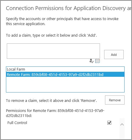
Currently, there still is no way to manage the service applications in the service farm from the consumer farm. So, just as when you set the permission for the consumer farm to use the Topology service, it is now time to add the consuming farm’s ID to the BDC service. The farm ID is already on the C: drive, so all you need to do paste the ID into the permissions window for the BDC service, check the name, add it to the group, and give Full Control, as illustrated in Figure 4-30.

The configuration of the BDC service farm is complete, and the consuming farm will treat the service as if it were being run locally.
Service application federation is a valuable tool when it comes to scalability and flexibility in a growing SharePoint 2013 environment. If you need to deploy a service farm, you should now have all the tools to succeed.