
Overview of Part II
Frame Structure
Chapter 10 will discuss the frame structure in both LTE and LTE-Advanced. In TDD, only one carrier frequency is used for uplink and downlink transmission where the uplink and downlink transmissions are only isolated in time. The TDD frame, also known as type 2 frame, is divided between the two transmissions using a guard period which is required to switch between the them. In every frame, either one or two sub-frames are split into a downlink part called DwPTS, a guard period, and an uplink part called UpPTS to facilitate the switching from downlink to uplink or vice versa. Other sub-frames are either allocated to uplink or downlink transmissions. The only exception is that sub-frames 0 and 5 are always allocated to downlink transmission.
UE States and State Transitions
3GPP extensively defines procedures for camping and network entry in LTE and LTE-Advanced. These are described in Chapter 11.
In LTE, a UE is required to perform certain steps in order to join a specific cell after being switched on. These steps compose the initial access procedure according to the LTE terminology. In particular, these are:
- Cell search and cell selection;
- Receiving system information; and
- Random access procedure.
Cell search is the process by which a UE acquires time and frequency synchronizations with a cell and detects eNB's ID. Acquiring the cell ID is by itself a two-stage process. First, the cell ID needs to be identified, and second the cell ID group is acquired. The standard identifies 504 PHY cell identities, which are divided hierarchically into two tiers: a 168 unique cell layer identity groups, with each group comprising three physical layer identities. The BS broadcasts the PHY identity over a signal called the Primary Synchronization Signal (PSS), and the cell layer identity group in the Secondary Synchronization Signal (SSS). Besides these signals, LTE BS transmits cell-specific reference signal that contains the downlink channel estimation for coherent demodulation and Channel Quality Indicator (CQI). The UE first looks for the PSS. This signal is normally transmitted in the last OFDM symbol of the first time slot of sub-frame 0 and sub-frame 5. The PSS enables the UE to get time synchronized on 5 ms scale. After receiving and analyzing the PSS signal, the UE obtains the radio frame timing and the cells' group identity from the SSS. The SSS signal is also transmitted in the 0 and 5 sub-frames. Hence, it is periodically received every 5 ms, which assists the UE to fully synchronize with the BS.
After successful cell search and selection, the next step is getting the system information. The UE configures the logical Broadcast Control Channel (BCCH) via the Broadcast Channel (BCH) and maps it to the Physical Broadcast Channel (PBCH) to be able to decode the Master Information Block (MIB). The MIB contains indispensable system information for the UE operation. MIB includes information about the number of available resource blocks, configuration of the Physical HARQ Indicator Channel (PHICH) and the System Frame Number (SFN). The MIB is transmitted in the first four OFDM symbols in the second time slot of sub-frame 0 and is repeated every fourth frame. After receiving the MIB, The UE reconfigure the BCCH channel and maps it to the PDSCH to receive System Information Block Type1 (SIB1), which includes the Physical Cell ID and scheduling information about other System Information Blocks Such as SIB2, SIB3, ... etc. After receiving the SIB1, The UE uses the scheduling information about the SIBx (x = 1, 2, 3...) to extract information about the SIB2, mainly in which subframe SIB2 is transmitted and reconfigures the BCCH to receive the SIB2. The SIB2 includes the common channel information, random access channel information and the random access preamble information, in addition to the information required for the HARQ procedure.
After receiving the system information, the UE is ready to start the random access procedure using the Random Access Channel (RACH) and common shared channel information to configure both channels. The UE starts the random access procedure to get its first allocated slots to transmit its uplink data for the first time. The UE contend on the uplink shared channel to send Random Access Preamble. If the preamble transmission is successful, the BS responds by the random access response. This response carries the Cell Radio Network Temporary Identifier (C-RNT) and uplink grant. After receiving the response, the UE can send connection requests to the BS on the CCCH to establish data connections to transmit its uplink data.
Quality of Service and Bandwidth Reservation
Chapter 12 reviews procedures for QoS management in LTE and LTE-Advanced. The LTE QoS framework is designed to provide an end-to-end QoS support. To achieve this, LTE provides QoS based on each flow requirements. LTE classifies flows into Guaranteed Bit Rate (GBR) GBR and non-GBR flows. Flows in LTE are mapped into radio bearers which are the over-the-air connections. To accommodate end-to-end QoS; LTE differentiates between two types of radio bearers, S1 bearers and EPS bearers. An S1 bearer is a connection between an eNB and either the MME or the S-GW, while an EPS bearer is a connection between the EPS and the MME or S-GW, or the S-GW and the P-GW. There are two types of bearers in LTE, default bearers and dedicated bearer. The former, which is a non-GBR bearer that does not provide bit rate guarantees, is initiated and established at the startup time to carry all traffic. On the other hand, the latter can be either a GBR or a non-GBR bearer. If it is a GBR bearer, the UE can specify the guaranteed bit rate, packet delay and packet loss error rate. Each dedicated bearer is characterized by a Traffic Flow Template (TFT) with QoS parameters associated to it. An uplink TFT is used to map the UE uplink Service Data Flow (SDF) to specific QoS parameters, with the mapping carried out at both the eNB and the UE. Mapping for the downlink TFT is carried out at the S-GW or the P-GW. LTE groups bearers into classes. Each class is identified by a scalar number called the QoS class Identifier (QCI). A QCI identifies a group of QoS parameters describing the packet forwarding treatment in terms of priority, tolerated delay, and packet error rate. Packet forwarding treatment is enforced by allocating radio resources for bearers through scheduling.
The scheduler resides in the eNB to dynamically allocate uplink and downlink resources over the uplink and downlink shard channel U-SCH and D-SCH, respectively. The uplink and downlink schedulers are invoked to allocate resources every Time Transmission Interval (TTI). The minimum TTI duration is of one subframe length; that is, 1 ms. uplink scheduling is performed per SC-FDMA PRB while downlink scheduling is performed per OFDMA PRB. eNB calculates the time-frequency resources given the traffic volume and the QoS requirements of each radio bearer. However, the resources are allocated per UE and not per radio bearer.
In addition to the dynamic allocation, LTE provides the flexibility to what is called persistent scheduling where the time-frequency resources can be implicitly reused in the consecutive TTIs according to a specific periodicity. Persistent scheduling reduces the overhead scheduling for applications such as VoIP. Scheduler design is not specified in the standard and is left for vendor implementation. An efficient scheduler, however, should take into account link channel quality and the buffer length of the radio bearers. It should also cater to fairness among the UEs based on their Service Level Agreements (SLA).
The operation of HARQ is highly related to the scheduling operation. LTE provides two mechanisms of error detection and correction through re-transmission namely, the HARQ mechanism at the MAC layer and the ARQ at the RLC layer. The ARQ functions less frequently than the HARQ and handles errors not detected by the HARQ process. HARQ is designed to be simple and fast to improve the QoS performance. This improvement is achieved by reducing delay and increasing the system throughput through the fast retransmission. The feedback signal of HARQ is a one bit ACK/NACK and the HARQ can be sent at every TTI.
LTE-Advanced carrier aggregation has an impact on both scheduling and HARQ. For HARQ, it is required in carrier aggregation [3] whether contiguous or non-contiguous, to have one independent HARQ entity per scheduled component carrier. Note that the maximum number of HARQ entities allowed by LTE-Advanced is eight entities for the FDD duplexing. For scheduling, similar to Release 8, each UE may be simultaneously scheduled over multiple component carriers. However, at most one random access procedure is scheduled per UE in any time frame. For TDD, it is required that the number of component carriers of the uplink should be equal to that of the downlink. As in LTE, a single component carrier is still mapped into one transport block.
Relaying in LTE-Advanced defines two types of HARQ and two types of scheduling: end-to-end and hop-by-hop HARQ and centralized and distributed scheduling. The end-to-end HARQ is simple because the eNB has full information about the status of each HARQ transmitted block. HARQ is performed at the eNB and the UE, the RS only relays data and control message between the two. In hop-by-hop HARQ, the RS not only forwards the data from/to eNB/UE, but also contributes in processing. For example, when a RS receives a message from the eNB destined to the UE, the RS decodes the message, checks the Cyclic Redundancy Check (CRC) and generates its own feedback (ACK or NACK).
In Relay LTE-Advanced centralized scheduling, eNB is responsible for scheduling all links of the network, relay links and UE links over the one and two hops distance of the network. The RS only forwards the received data and signaling from eNB without any processing. In LTE-Advanced relaying networks employing distributed scheduling, the scheduler resides at both the eNB and the RS. The eNB only schedules resources for the eNB-RS links as well as for UEs connected directly to it. On the other hand, the RS schedules resources for RS-UE links that are two hops away from the eNB. Consequently, the eNB does not need to receive the Channel State Information (CSI) of the RS-UE link, which makes distributed scheduling consume less signaling and overhead. Distributed scheduling can only be employed in Type I relaying networks.
Mobility Management
3GPP Mobility management is described in Chapter 13. LTE supports various users' mobility by standardizing handover essential signaling and processes [4]. There are three handover types in LTE:
- Intra-Handover: Occurs within the same LTE network nodes (intra-MME and intra-S-GW).
- Inter-Handover: Occurs between different LTE networks nodes (inter-MME and Inter-S-GW).
- Inter-RAT: Occurs between different radio technology networks, for example WiMAX and LTE, UMTS and LTE, etc.
Also, there are two types of handover decisions based on the decision-making entity. The first is the network evaluated decision, where the eNB makes the decision while the second is the mobile evaluated handover, where the UE takes the decision of handover and conveys it to the serving eNB. In this type, the eNB can decide to either, meet or deny this request based on the current network conditions.
Intra-Handover
Intra-Handover is performed to handover a UE from a serving eNB to a target eNB over the X2 interface with the same MME and serving gateway. In general, LTE Intra handover processes include procedures to measure downlink channel quality between the eNB and the UE, procedure to process the channel quality data collected by UE, which is done by the UE, procedure to send the channel quality processed data from the UE to the serving eNB, and finally procedures used by the eNB to make a handover decision based on the data received from UE. The above mentioned procedures are grouped under one stage of the handover process called handover preparation which is the first of three intra-handover stages defined by LTE. The other two stages are handover execution and handover completion. The functionalities of these three stages are summarized next:
- Handover Preparation: In this stage, the UE, the serving eNB and the target eNB are all involved with specific tasks performed by each. First, the UE processes and prepares a channel quality measurement report and sends it to the serving eNB. To carry out this task at the UE, the serving eNB should configure and trigger the UE measurement procedure. Once the serving eNB receives the measurement report, the serving eNB processes the report to come up with a handover decision based on the level of the channel strength. If the serving eNB decides to hand the UE over to a target eNB, it sends a handover request to the target eNB. When the target eNB receives this request, it performs an admission control request based on the resources indicated to be required for the UE's radio bearers. If sufficient resources are available, the target eNB acknowledges the request with a handover request acknowledgement; otherwise it sends a handover preparation failure message to the serving eNB. This terminates that handover preparation procedure. If beyond a certain time the serving eNB does not receive an indication of either an acknowledgement or a failure, it sends a handover cancel and indicates the cause as expired timer. If a serving eNB sends a handover cancel requests, it disregards further messages from the target eNB. If the handover request acknowledgment is received, the serving eNB sends the handover command to the UE which includes all the necessary information for the UE to access the target cell. This finalizes the handover preparation stage.
- Handover Execution: The UE uses the information included in the handover command to execute the handover process. UE performs different tasks during this stage. It performs the random access procedure over the RACH to connect to the target cell. Also, it acquires time synchronization with the target eNB. Timing advance for the UE is performed at the uplink and the handover confirmation message is given to the target eNB by the UE. This step is important to maintain the frequency subcarrier orthogonality necessary to mitigate intra-cell interference.
- Handover Completion: This is the last stage, where the target eNB sends a confirmation and path switch request. A request and response for modifying the UE's radio bearers are then processed by the serving GW and, in turn, the PDN GW. Once completed, the serving GW responds to the path switch request by redirecting the UE's downlink data to the target side, sending an end marker to the serving eNB. In turn, the serving eNB sends another end marker to the target eNB and the MME acknowledges the target eNB's path switch request. Finally, the target eNB sends a context release message to the serving eNB. Upon reception of the context release message, the serving eNB releases control and data connection resources. This finalizes the handover procedure.
Note here that if the handover cannot be initiated over an X2 interface, the S1 mobility management oversees the handovers.
Inter-Handover
This type of handover is initiated over an S1 interface when the UE roams between two different MME areas; that is, the serving eNB and the target eNB are controlled by two MMEs with the same S-GW or two MMEs and two different S-GWs: serving MME-serving S-GW and target MME-target S-GW. Inter-handover is similar to intra-handover over S1 interface except for the involvement of two MMEs.
The handover is initiated by sending a handover required message by the serving eNB. This initiates an S1 handover preparation phase. The serving MME detects that the target eNB is in another MME. Hence, it forwards the request to the target MME. The target MME creates the S1 logical connection toward the target eNB and sends the S1 HANDOVER REQ over it. If the target MME judges that the handover can be realized, it sends a handover command. The target MME performs a handover resource allocation by sending a handover request message to the target eNB. Upon receiving the request message, the target eNB makes the appropriate resource allocation, context preparation and relevant security authentications for the UE.
downlink data packets are forwarded from the serving-eNB to target-eNB via the S-GW during the handover if the S-GW remains the same. An indication of a successful handover is sent by the target eNB to the target-MME using a handover notify message.
Inter-RAT Handover
Inter-RAT handovers will be discussed at length in Part-III of the book. However, similar to inter and intra handovers, an inter-RAT handover consists of three stages: preparation, execution and completion. However, the procedure in each stage differs by the type of technology involved in the handover with the LTE network. LTE and LTE-Advanced generally defines the signaling required to perform Inter-RAT handover, and leaves all other issues for the IEEE 802.21 standard, which defines mechanisms for Media Independent Handovers.
Handover in Femtocells
LTE standard defines three types of handovers in femtocells [5]:
- Inbound: Handover from macrocell to femtocell. It is similar to handover from a macrocell to macrocell over S1 interface. In this handover, the serving eNB recognizes that the target cell is HeNB from the Tracking Area Code (TAC) and HeNB ID. Using this information, it identifies the HeNB gateway and sends the handover request to MME, which will forward the request to HeNB gateway. In turn, the HeNB gateway forwards the request to the target HeNB.
- Outbound: Handover from femtocell to macrocell. The HeNB gateway receives the handover request from the serving HeNB and forward it to the MME over S1 interface. MME forwards the request to the target eNB. Inbound and Outbound handovers are expected not to be soft handovers due to the limitations of the frequency resources at the femtocells.
- Inter-Femtocell: Handover between femtocells. The HeNB takes care of the femtocell to femtocell handover over the S1 interface.
Handover in Relay LTE
Handover procedures in relay LTE is changed by the introduction of the RSs. There are two types of handover processes in relay LTE: centralized and distributed. The centralized process is almost similar to the handover of LTE except the introduction of the RS. In centralized process, the handover request is initiated by the serving eNB. The relay transparently forwards the measurement reports and requests from the UE. The serving eNB and the target eNB are in control of the handover process with the assistance of the RSs forwarding messages to the UE transparently.
In distributed process, the serving RS initiates the handover. The handover procedures are carried out with the collaboration of the RS (serving and target) to successfully conduct the handover.
Distributed process is similar to the LTE handover process with the difference that the serving and the target RSs are in control of the handover procedures besides the corresponding eNBs. In this type of handover, the serving RS receives the measurement report from the UE and forwards it to the serving eNB. Mean-while, in centralized handover, this report is directly sent to the serving eNB. The admission control is carried out by the target eNB on the backhaul link and the target RS on the relay link in distributed handover, while it is performed by the target eNB on the backhaul and relay link without intervening of the target RS. Synchronization and timing advance for the UE is performed at the uplink and the handover confirmation message is given to the target RS by the UE. The target RS sends the confirmation message to the target eNB, which finalizes the handover procedure as per LTE handover procedures. Finally, the target eNB sends request to the serving eNB to release network resources. Finally, this latter forwards the command to the serving RS to release resources of the UE.
Security
Chapter 14 describes the security architectures and procedures in 3GPP. The separations of user and control planes and the access and NAS in LTE/SAE result in an implicit security requirement. LTE establishes security association with access stratums between the UE and eNB only if the UE is connected. However, if a UE is in idle mode, the eNB does not preserve states about a UE in idle mode. In UE idle mode the NAS messages are still exchanged. Hence, non-stratum security associations are established between the UE and the MME.
3GPP describes an extensive two layer security architecture that also utilizes the Internet Engineering Task Force (IETF) security solutions for its IP core. The security architecture is maintained in LTE-A, with some enhancements concerning more capable encryption and integrity algorithms being utilized.
There are five sets of security feature groups defined in LTE:
- Network access security: The set of security features that provide users with secure access to services, which in particular protect against attacks on the (radio) access link.
- Network domain security: The set of security features that enable nodes to securely exchange signaling data, user data (between the Access Network (AN) and the Serving Network (SN), and within the (AN), and protect against attacks on the wireless network.
- User domain security: The set of security features that secure access to UEs.
- Application domain security: The set of security features that enable applications in the user and in the provider domain to securely exchange messages.
- Visibility and configurability of security: The set of features that enables the user to inform himself whether a security feature is in operation or not and whether the use and provision of services should depend on the security feature.
EPS Authentication and Key Agreement (AKA)
The EPS AKA produces key hierarchy material forming a basis for the user plane, RRC and the NAS ciphering keys as well as RRC and NAS integrity protection keys. These keys are used to protect user plane traffic between the UE and the network. The key hierarchy is derived using cryptographic functions. It includes the following keys KeNB, KNASint, KNASenc, KUPenc, KRRCint and KRRCenc, which are respectively the keys for the eNB, the NAS traffic without encryption, NAS traffic with encryption, User Plane traffic with encryption, RRC traffic without encryption and RRC traffic with encryption. Keys for unencrypted traffic are used to verify integrity.
The main advantages of key hierarchy and cryptographic derivation are:
- If one attacker gets hold of one key, he cannot be able to generate other keys because they are at an upper layer in hierarchy.
- Keys are bound to the location and purpose they are used for. This prevents using a key in different access networks if this key is compromised; that is, key used in one AN cannot be used in another.
- Keys used between UE and eNB are changed regularly (e.g. during the initial network entry or handover) without a need to change the root key.
The MME sends to the Universal Subscriber Identity Module (USIM) a random challenge, an authentication token, in addition to the KASME. The KASME key is a base key, from which NAS keys, KeNB keys and H are derived. The KASME is never transported to an entity outside of the EPC, but KeNB and NH are transported to the eNB from the EPC. From the KeNB, the eNB and UE can derive the UP and RRC Keys.
Handover Security
When handover is initiated by the serving eNB, it is required to transfer security parameters to the target eNB in a trusted environment. To achieve this, LTE introduces the concept of forward security as the property that, for an eNB with knowledge of a KeNB, shared with a UE; it shall be computationally infeasible to predict any future KeNB that will be used between the same UE and another eNB. Hence, it is infeasible for an attacker who compromised either, a serving or a target eNBs and obtained its key, to deduce or know the key of the other one. Meanwhile, the UE has full information to deduce the required key. In case a target eNB is compromised during handover (backward security), LTE defines a procedure to ensure keeping previous traffic secured. In this case a serving eNB derives a new key from current key and only transfer this key to the target eNB.
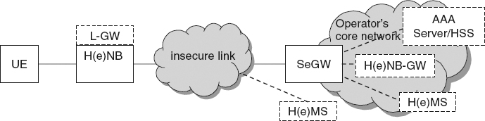
Figure 9.6 Security system architecture of HeNB.
LTE Relay Security
Current LTE standard do not specify or resolve security issues on the relay link and the backhaul link. However, it provides general guidelines for LTE relay security. LTE relay assumes the RS has secure environment for forwarding and processing data. It mandates mutual authentication between RS and network using AKA and RS device authentication. The standard requires binding between these two authentications procedures. It necessitates the control plane traffic to be integrity protected while the user plane traffic integrity protection is left optional. Other mandates of LTE relay security is the confidentiality protection between the RS and the network. Until March, 2011, work on LTE relay security is ongoing to evaluate solutions and procedures before standardization.
LTE Femtocell Security
Figure 9.6 shows the security architecture of HeNB [6]. As the figure shows, HeNB accesses the core network via Security Gateway (SeGW), while the link between HeNB and SeGW may be insecure. Once HeNB accesses the core network, SeGW performs a mutual authentication with the HeNB. If a HeNB is authenticated, a security tunnel is established between it and the SeGW to protect information transmitted in backhaul link. The security tunneling protocol can be IPsec or any other layer two security protocol even though LTE standard mandates implementation of the security channel. However it leaves using it optional based on an operator policy. In the CSG case, the HeNB-GW performs the mandatory access control, while HeNB performs the optional access control in case of OSG HeNBs.
Different security procedures are defined for HeNB security system, mainly:
- Device integrity check performed by HeNB and the Trusted Environment (TrE) upon booting and before connecting to the core network and/or to the HeNB Management System (H(e)MS). TrE is a logical entity which provides a trustworthy environment for the execution of sensitive functions and the storage of sensitive data.
- Device validation and authentication of the HeNB device platform, where a device implicitly indicates its validity to the SeGW or HeMS by successful execution of device authentication.
- Device Authentication may optionally be followed with an EAP-AKA-based hosting party authentication exchange.
- As a result of the authentication procedure, IPsec tunnel establishment by HeNB. At least one IPsec tunnel is set up to protect all signaling, user, and management plane traffic over the interface between H(e)NB and SeGW.
- Optionally an AAA server may be used to verify the authorization of the H(e)NB to connect to the operator's network based on the authenticated device identity extracted from the H(e)NB certificate.
- Location verification performed by the H(e)MS and/or HNB-GW to ensure the H(e)NB location satisfies various security, regulatory and operational requirements.