
C H A P T E R 3
![]()
Handling Input on Windows Phone
Handling input is a critical aspect of any application, but it is an especially unique challenge on a mobile device. The first consideration is that the user is most likely not sitting in a comfortable chair sipping coffee, casually browsing the Internet. A mobile application user is most likely on the go, looking to just get a task done or find the needed information and be on their way.
The second consideration is that user input on a mobile device is quite different than handling input on the PC or even on the XBOX 360 for XNA Framework game development. A Windows Phone mobile device may or may not have a physical keyboard, so you cannot author your application to depend on it. Even at 800px x480px screen resolution, screen real estate is still at a premium.
Mobile devices have unique hardware input capabilities for innovative user experiences, such as capacitive touch, accelerometer, and location. With Windows Phone 7 OS 7.1, available sensors are expanded to include compass, camera capture, gyroscope, and motion sensor. You may be wondering about existing devices. Many existing devices ship with compass hardware already but not a gyroscope.
The motion sensor Microsoft provides uses a combination of accelerometer, compass, and gyroscope inputs to produce a nice, clean API to determine yaw, pitch, and roll of a device. For hardware without a gyroscope but with a compass, the API simulates it using the accelerometer. It is not as good as having a gyroscope, but it still allows you to build for scenarios like augmented reality with camera capture and have them run acceptably on existing hardware if it includes a compass.
![]() Note In Windows Phone 7.5 compass and gyroscope are optional, but if a device includes a gyroscope it also includes a compass. Applications should identify the dependency as part of the application description in marketplace.
Note In Windows Phone 7.5 compass and gyroscope are optional, but if a device includes a gyroscope it also includes a compass. Applications should identify the dependency as part of the application description in marketplace.
In this chapter, I cover handling user input in both Silverlight and XNA Windows Phone applications starting first with keyboard, touch input, including single touch and multi-touch. Then we dive into the individual sensors including coverage of the new capabilities available in Windows Phone OS 7.1.
![]() Note The gesture samples use the Silverlight for Windows Phone Toolkit, available at
Note The gesture samples use the Silverlight for Windows Phone Toolkit, available at http://silverlght.codeplex.com. Please download the toolkit to compile the sample code.
![]() Note This code in this chapter is broken up into two separate Solutions in the sample source code: Ch03_HandlingInput and Ch03_HandlingInput_Part2. Sample code starting in the location sample on forward is in the Part 2 solution.
Note This code in this chapter is broken up into two separate Solutions in the sample source code: Ch03_HandlingInput and Ch03_HandlingInput_Part2. Sample code starting in the location sample on forward is in the Part 2 solution.
The Keyboard
The last thing a mobile user wants to do is type on a mobile keyboard, but it is inevitable for many applications to require some form of text input. In this section I discuss keyboard capabilities and API enhancements to ease typing on the keyboard on Windows Phone devices.
Physical Keyboard
Windows Phone devices may also have a hardware slide-out keyboard, but your application will not pass certification in AppHub if it is dependent upon the hardware keyboard. Otherwise, from a software development perspective, programming for hardware keyboard input “just works.” Of the six devices available at Windows Phone launch, only one had a full slide-out keyboard, and another had a vertical QWERTY keyboard. The other four devices were pure touch devices without a physical keyboard.
Soft Input Panel (SIP) Keyboard
All Windows Phone devices have a SIP keyboard used for entering text. Typing on the SIP keyboard built into Windows Phone is a pretty comfortable means of entering text; however, it is still a small keyboard, so anything that a developer can do to ease typing can really help improve the overall user experience.
Programming with the Keyboard
Typing text on a mobile phone should be minimized as much as possible, but if text input is required, a developer should take advantage of capabilities to make typing as simple as possible. In the next section I cover InputScope, which is a must-have feature to take advantage of when typing is required in your Windows Phone applications.
When testing keyboard input, you will be tempted to type on your PC keyboard; however, it does not work. You must use the mouse with the SIP keyboard in the Emulator for input.
![]() Tip Click the Pause/Break button on your PC keyboard to enable typing in the emulator with your PC keyboard instead of having to use the mouse to “touch” the SIP.
Tip Click the Pause/Break button on your PC keyboard to enable typing in the emulator with your PC keyboard instead of having to use the mouse to “touch” the SIP.
InputScope
The InputScope property is available on the TextBox control, which is the primary control for text input. InputScope lets the developer customize the keyboard for the expected type of input. For example, the default behavior is that when you click into a TextBox, the SIP keyboard pops up, as shown in Figure 3–1.

Figure 3–1. Default SIP keyboard
The second TextBox has an InputScope of Text, which enables word selection just above the keyboard, as shown in Figure 3–2.
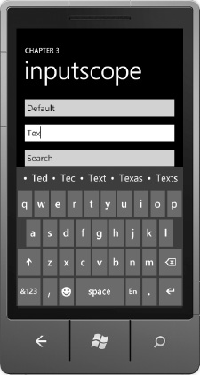
Figure 3–2. InputScope of Text SIP keyboard with word suggestion
With just one simple attribute, text input becomes much easier for the end user. Figure 3–3 shows three additional text input options, which I explain just after the figure.
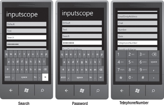
Figure 3–3. Search, Password, and TelephoneNumber InputScope customizations
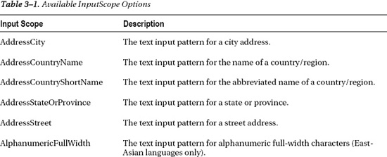
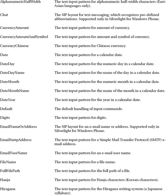
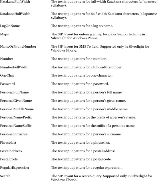
Configuring an InputScope of Search turns the Enter key into a GO key with the idea that the user enters a search keyword and then clicks Enter to kick off a search. Password is not actually an InputScope. It is a custom TextBox class named PasswordBox that automatically hides data entry as the user types. An InputScope of TelephoneNumber brings up a phone keypad. As you can see, all of these could come in handy as you develop your application UI and optimize input for the end user. Table 3–1 lists the available InputScope options and their descriptions, reprinted here for your convenience from the Windows Phone documentation.

Let's now shift gears and explore the available keyboard events.
Keyboard Events
There are two keyboard events available on the TextBox, as well as pretty much any other object that inherits from UIElement: the KeyDown and KeyUp events. Both events have a KeyEventArgs class in its parameters that provides access to the Key and PlatformKeyCode values native to the platform. It also provides access to the OriginalSource property that represents the control that raised the Keyboard event, as well as a Handled member to indicate that the key has been processed.
This completes our discussion of keyboard events. In general, typing should be minimized in a mobile application for the reasons listed previously, i.e., small screen, small keyboard, and so on. Mobile devices are optimized for touch input, especially modern devices with highly responsive capacitive touch screens that do not require a stylus. Let's now focus on touch input.
Touch Input
Most modern mobile devices that have touch screens do not require a stylus, which was necessary for resistive touch-based screens. Modern mobile devices are capacitive touch and respond very well to touch with a finger.
Windows Phone supports up to four multi-touch contact points for XNA Framework development. Silverlight for Windows Phone supports two multi-touch contact points. As part of the platform, there is a touch driver and gesture engine under the covers that provides a consistent detection capability across hardware device OEMs and across applications.
As mentioned previously, Silverlight for Windows Phone is based on Silverlight 3. The Windows Phone product team took the Silverlight 3 controls and APIs and optimized the controls for performance, for look and feel via control templates and styles and for input. The next section covers single-point touch as it relates to the controls optimized for Windows Phone.
Single-Point Touch
When a user clicks a Button control, TextBox control, ListBox control and the like on Windows Phone, it is single-point touch. For consistency, single-point touch events are translated to the Mouse events that you are familiar with when programming desktop Silverlight, Windows Forms, or other application frameworks. For example, touching a button appears as a Click event. Tapping to type text in a TextBox or touch a TextBlock control fires a MouseEnter, a MouseLeftButtonDown, a MouseLeftButtonUp, and a MouseLeave event.
The Chapter 3 SinglePointTouch project TextControlsMouseEventsPage.xaml page shows these events firing when you interact with the TextBox and TextBlock controls. You will notice when testing on a device that sometimes multiple MouseEnter/MouseLeave pairs can fire. You can also see multiple MouseMove events fire as well as a result of small movements in your finger when interacting with the controls. It's something to consider when using these events with touch, as opposed to mouse clicks on the desktop, and why discrete events like listening for click or gestures is recommended except when discrete touch points are required. Figure 3–4 shows the UI with the mouse events trace.
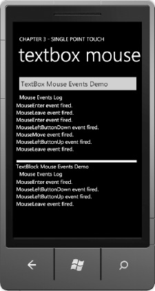
Figure 3–4. Text controls mouse events demo
Listing 3–1 shows the TextControlsMouseEventPage.xaml code file with the XAML markup.
Listing 3–1. WMAppManifest.xml Configuration File
<phone:PhoneApplicationPage

  x:Class="SinglePointTouch.Pages.TextBoxMouseEventPage"

  xmlns="http://schemas.microsoft.com/winfx/2006/xaml/presentation"

  xmlns:x="http://schemas.microsoft.com/winfx/2006/xaml"

  xmlns:phone="clr-namespace:Microsoft.Phone.Controls;assembly=Microsoft.Phone"

  xmlns:shell="clr-namespace:Microsoft.Phone.Shell;assembly=Microsoft.Phone"

  xmlns:d="http://schemas.microsoft.com/expression/blend/2008"

  xmlns:mc="http://schemas.openxmlformats.org/markup-compatibility/2006"

  FontFamily="{StaticResource PhoneFontFamilyNormal}"

  FontSize="{StaticResource PhoneFontSizeNormal}"

  Foreground="{StaticResource PhoneForegroundBrush}"

  SupportedOrientations="Portrait" Orientation="Portrait"

  mc:Ignorable="d" d:DesignHeight="768" d:DesignWidth="480"

  shell:SystemTray.IsVisible="True">


  <!--LayoutRoot is the root grid where all page content is placed-->

  <Grid x:Name="LayoutRoot" Background="Transparent">
<Grid.RowDefinitions>
<RowDefinition Height="Auto"/>
<RowDefinition Height="*"/>
</Grid.RowDefinitions>
<!--TitlePanel contains the name of the application and page title-->
<StackPanel x:Name="TitlePanel" Grid.Row="0" Margin="12,17,0,28">
<TextBlock x:Name="ApplicationTitle" Text="CHAPTER 3 - SINGLE POINT TOUCH"
Style="{StaticResource PhoneTextNormalStyle}"/>
<TextBlock x:Name="PageTitle" Text="textbox mouse events" Margin="9,-7,0,0"
Style="{StaticResource PhoneTextTitle1Style}"/>
</StackPanel>
<!--ContentPanel - place additional content here-->
<Grid x:Name="ContentPanel" Grid.Row="1" Margin="12,0,12,0">
<StackPanel Orientation="Vertical">
<TextBox HorizontalAlignment="Left" x:Name="MouseEventsTextBox"
Text="TextBox Mouse Events Demo" Width="460" Height="72"
MouseEnter="MouseEventsTextBox_MouseEnter"
MouseLeave="MouseEventsTextBox_MouseLeave"
MouseLeftButtonDown="MouseEventsTextBox_MouseLeftButtonDown"
MouseLeftButtonUp="MouseEventsTextBox_MouseLeftButtonUp"
MouseMove="MouseEventsTextBox_MouseMove"
MouseWheel="MouseEventsTextBox_MouseWheel" />
<TextBlock Height="30" HorizontalAlignment="Left" Margin="12,0,0,0"
x:Name="MouseEventStatusText" Text="Mouse Events Log"
Width="438" />
<ListBox Height="217" x:Name="MouseEventLogListBox" />
<Rectangle Fill="#FFF4F4F5" Height="10" Stroke="Black" Margin="0,0,6,0"/>
<TextBlock TextWrapping="Wrap" Text="TextBlock Mouse Events Demo"
Margin="0" Name="TextBlockMouseEventsDemo"
MouseEnter="TextBlockMouseEventsDemo_MouseEnter"
MouseLeave="TextBlockMouseEventsDemo_MouseLeave"
MouseLeftButtonDown="TextBlockMouseEventsDemo_MouseLeftButtonDown"
MouseLeftButtonUp="TextBlockMouseEventsDemo_MouseLeftButtonUp"
MouseMove="TextBlockMouseEventsDemo_MouseMove"
MouseWheel="TextBlockMouseEventsDemo_MouseWheel" />
<TextBlock Height="30" HorizontalAlignment="Left" Margin="12,0,0,0"
x:Name="MouseEventStatusTextBlock" Text="Mouse Events Log"
Width="438" />
<ListBox Height="220" x:Name="MouseEventLogListBox2" />
</StackPanel>
</Grid>
</Grid>
</phone:PhoneApplicationPage>
In Listing 3–1, you can see the event handler assignments like this one assigning an event handler to the MouseEnter event for the MouseEventsTextBox object
MouseEnter="MouseEventsTextBox_MouseEnter"
The code-behind file has the related event handlers that simply write a text message to the MouseEventLogListBox like this one:
private void MouseEventsTextBox_MouseEnter(object sender, MouseEventArgs e)

{

  MouseEventLogListBox.Items.Add("MouseEnter event fired.");

}
Now that we have covered the mouse events, we will next look at how to use the mouse events for raw touch.
Raw Touch with Mouse Events
In addition to indicating a “click” or touch even, mouse events can be used for raw touch. An example of raw touch is drawing with your finger, where you need individual touch locations. What enables raw touch with mouse events is the MouseEventArgs class passed into the mouse events. The following are the key properties of the MouseEventArgs class:
GetPosition(UIElement relativeTo):Gets the position of the mouse event in relation to the passed in object. Returns aPointobject.- OriginalSource: Provides a reference to the object that raised the event.
- StylusDevice: Returns a StylusDevice object that includes the set of stylus points associated with the input.
The StylusDevice object contains a GetStylusPoints method that returns a StylusPointsCollection that we can draw an object onscreen to represent user touches. The StylusPoint class is enhanced over the Point class with the StylusPoint.PressureFactor property. Because PressureFactor is a float, we can assign it to the Opacity property of the object we draw onscreen to represent touches such that the Opacity indicates whether it is a light or heavy press on the screen. So a light pressure press will have a lower opacity when drawn on screen.
In the next couple of sections we will build a mini finger drawing application that includes multi-color selection, ListBox customizations, animations, the application bar, and basic drawing functionality.
Setting Up the Basic UI
Add a Windows Phone Portrait Page new item to the SinglePointTouch project. Uncomment the sample ApplicationBar code at the bottom of the page. We will use the ApplicationBar to implement commands to clear the drawing canvas, set the touch object size, and so on.
At the top we set the title and subtitle for the page. In the default ContentPanel Grid object, we add a Canvas object. On top of the Canvas object is a Rectangle that receives the mouse events. We take advantage of absolute positioning in the Canvas object to place the objects that represent user touches using X and Y coordinates provided by StylusPoint objects. The following is a XAML snippet of the TitlePanel and ContentPanel:
<!--TitlePanel contains the name of the application and page title-->

<StackPanel x:Name="TitlePanel" Grid.Row="0" Margin="12,17,0,28">

  <TextBlock x:Name="ApplicationTitle" Text="CHAPTER 3 - SinglePointTouch"

              Style="{StaticResource PhoneTextNormalStyle}"/>

  <TextBlock x:Name="PageTitle" Text="finger painting" Margin="9,-7,0,0"

              Style="{StaticResource PhoneTextTitle1Style}"/>

</StackPanel>
<!--ContentPanel - place additional content here-->
<Grid x:Name="ContentPanel" Grid.Row="1" Margin="24,0,0,0">
<Canvas x:Name="DrawCanvas" >
<Rectangle Fill="White" Stroke="Black"
MouseMove="Rectangle_MouseMove" Width="456" Height="535" />
</Canvas>
</Grid>
The following is the Rectangle_MouseMove event handler on the Rectangle object and related helper method:
private void Rectangle_MouseMove(object sender, MouseEventArgs e)

{

  foreach (StylusPoint p in e.StylusDevice.GetStylusPoints(DrawCanvas))

  {

    Ellipse ellipse = new Ellipse();

    ellipse.SetValue(Canvas.LeftProperty, p.X);

    ellipse.SetValue(Canvas.TopProperty, p.Y);

    ellipse.Opacity = p.PressureFactor;

    ellipse.Width = 20d;

    ellipse.Height = 20d;

    ellipse.IsHitTestVisible = false;

    ellipse.Stroke = new SolidColorBrush(Colors.Black);

    ellipse.Fill = new SolidColorBrush(Colors.Black);

    DrawCanvas.Children.Add(ellipse);

  }

}
The application uses the MouseMove event and the StylusPointsCollection to draw small Ellipse objects to the screen as you drag the mouse on the emulator or finger on a device across the screen. Figure 3–5 shows the UI in action.

Figure 3–5. Basic finger painting UI
Finger painting without multiple colors is boring. Let's add a ListBox and populate it with the built-in System.Windows.Media.Colors collection so that the user can select an item and change the “finger paint” color. We first create a couple of classes to encapsulate the System.Windows.Media.Colors collection since we cannot data bind directly to it. See Listing 3–2.
Listing 3–2. The ColorClass Code File
public class ColorClass

{

  public Brush ColorBrush { get; set; }

  public String ColorName { get; set; }

}
It contains a Brush to represent the RGB values for the color and a text name for the color. We need a collection of ColorClass objects to bind to. Listing 3–3 has the simple class that generates a collection of ColorClass objects.
Listing 3–3. The ColorsClass Code File
public class ColorsClass

{

  List<ColorClass> _colors;
public ColorsClass()
{
_colors = new List<ColorClass>();
_colors.Add(new ColorClass() {
ColorBrush = new SolidColorBrush(Colors.Blue), ColorName = "Blue" });
_colors.Add(new ColorClass() {
ColorBrush = new SolidColorBrush(Colors.Brown), ColorName = "Brown"});
_colors.Add(new ColorClass() {
ColorBrush = new SolidColorBrush(Colors.Cyan), ColorName = "Cyan"});
_colors.Add(new ColorClass() {
ColorBrush = new SolidColorBrush(Colors.DarkGray),
ColorName = "DarkGray"});
_colors.Add(new ColorClass() {
ColorBrush = new SolidColorBrush(Colors.Gray), ColorName = "Gray"});
_colors.Add(new ColorClass() {
ColorBrush = new SolidColorBrush(Colors.Green), ColorName = "Green"});
_colors.Add(new ColorClass() {
ColorBrush = new SolidColorBrush(Colors.LightGray),
ColorName = "LightGray" });
_colors.Add(new ColorClass() {
ColorBrush = new SolidColorBrush(Colors.Magenta),
ColorName = "Magenta" });
_colors.Add(new ColorClass() {
ColorBrush = new SolidColorBrush(Colors.Orange), ColorName="Orange"});
_colors.Add(new ColorClass() {
ColorBrush = new SolidColorBrush(Colors.Purple), ColorName="Purple"});
_colors.Add(new ColorClass() {
ColorBrush = new SolidColorBrush(Colors.Red), ColorName = "Red"});
_colors.Add(new ColorClass() {
ColorBrush = new SolidColorBrush(Colors.White), ColorName = "White"});
_colors.Add(new ColorClass() {
ColorBrush = new SolidColorBrush(Colors.Yellow), ColorName = "Yellow"});
_colors.Add(new ColorClass() {
ColorBrush = new SolidColorBrush(Colors.Black), ColorName = "Black"});
}
public List<ColorClass> ColorsCollection
{
get { return _colors; }
}
}
All of the work is done in the constructor using abbreviated syntax to create the collection. Data bind the ColorListBox.ItemsSource to the ColorsClass.ColorsCollection either manually in Visual Studio or with Expression Blend. By default the ColorListBox scrolls vertically. To have the ColorListBox scroll horizontally, right-click on the ColorListBox in Expression Blend and select Edit Additional Templates Edit Layout of Items (ItemsPanel), Edit a Copy…to edit the template. Drop a StackPanel on to the root ItemsPanelTemplate object. Configure the StackPanel to have Orientation set to Horizontal and that's it: the ColorListBox will scroll horizontally. The last bit of customization is to create an ItemTemplate for ColorListBox. ColorListBox.ItemsSource data binds to the collection. The ItemTemplate has that as its context, so the ItemTemplate data binds to individual records. The following is the ItemTemplate:
<DataTemplate x:Key="FingerPaintingColorTemplate">

  <StackPanel Orientation="Vertical">

    <Rectangle Fill="{Binding ColorBrush}" HorizontalAlignment="Left"

      Height="95" Stroke="Black" VerticalAlignment="Top" Width="95" Margin="4,4,4,0"/>

    <TextBlock HorizontalAlignment="Center" TextWrapping="Wrap"

      Text="{Binding ColorName}" VerticalAlignment="Center" Margin="0"/>

  </StackPanel>

</DataTemplate>
The ColorListBox DataTemplate consists of a Rectangle that displays the color based on the ColorClass.ColorBrush property and a TextBlock that displays the name of the color based on the ColorClass.ColorName property. Figure 3–6 shows the resulting work.

Figure 3–6. Finger painting UI with ColorListBox
In PhoneApplicationPage_Loaded, set the SelectedIndex on ColorListBox so that a color is always selected.. The drawing code is updated to obtain the ColorListBox.SelectedItem object in order to set the brush color for the Ellipse.
private void Rectangle_MouseMove(object sender, MouseEventArgs e)

{

  foreach (StylusPoint p in e.StylusDevice.GetStylusPoints(DrawCanvas))

  {
Ellipse ellipse = new Ellipse();
ellipse.SetValue(Canvas.LeftProperty, p.X);
ellipse.SetValue(Canvas.TopProperty, p.Y);
ellipse.Opacity = p.PressureFactor;
ellipse.Width = 20d;
ellipse.Height = 20d;
ellipse.IsHitTestVisible = false;
ellipse.Stroke = ((ColorClass)ColorListBox.SelectedItem).ColorBrush;
ellipse.Fill = ((ColorClass)ColorListBox.SelectedItem).ColorBrush;
DrawCanvas.Children.Add(ellipse);
}
}
The application will now allow finger painting using the selected color in the ColorListBox. In the next section we will expand the painting functionality in the application.
Expand Painting Functionality
Let's now add additional painting functionality to make the application more usable, such as to clear the drawing surface, increase the touch pencil size, decrease the touch pencil size, show/hide the color palate to change drawing color, and to set the background for the image. Here is how the UI is set up:
- Clear: Erase the drawing surface (trashcan icon).
- Touch color: Shows the color palate to set the drawing color (edit pencil icon).
- Pencil size: Increases pencil size (plus sign icon).
- Pencil size: Decreases pencil size (minus sign icon).
- Set background color menu item: Shows the color palate to set the background color.
In Expression Blend, edit the Application Bar to provide four application bar icons and one menu item. Expression Blend provides access to the built-in icons, as shown in Figure 3–7.
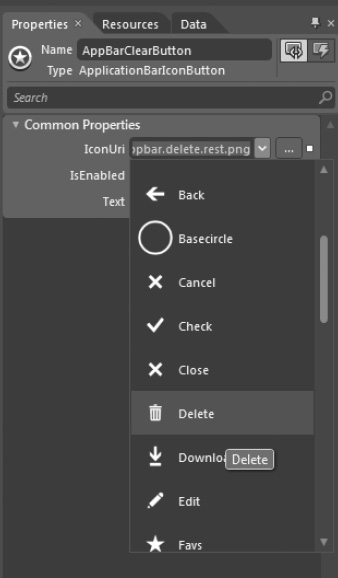
Figure 3–7. Finger painting UI with ColorListBox
Once the application bar icons and menu item are configured visually in Blend, set the ColorListBox control's Visibility to Visibility.Collapsed so that it is only visible when needed. We switch over to Visual Studio to add the event handlers in XAML for the Application Bar button icons and menu item. Listings 3--4 and 3--5 have the full source code of the mini-application.
Listing 3–4. The FingerPaintingPageMouseEvents.xaml Code File
<phone:PhoneApplicationPage

  xmlns="http://schemas.microsoft.com/winfx/2006/xaml/presentation"

  xmlns:x="http://schemas.microsoft.com/winfx/2006/xaml"

  xmlns:phone="clr-namespace:Microsoft.Phone.Controls;assembly=Microsoft.Phone"
xmlns:shell="clr-namespace:Microsoft.Phone.Shell;assembly=Microsoft.Phone"
xmlns:d="http://schemas.microsoft.com/expression/blend/2008"
xmlns:mc="http://schemas.openxmlformats.org/markup-compatibility/2006"
xmlns:SinglePointTouch="clr-namespace:SinglePointTouch"
x:Class="SinglePointTouch.Pages.FingerPaintingPageMouseEvents"
SupportedOrientations="Portrait" Orientation="Portrait"
mc:Ignorable="d" d:DesignHeight="696" d:DesignWidth="480"
shell:SystemTray.IsVisible="True" Loaded="PhoneApplicationPage_Loaded">
<phone:PhoneApplicationPage.Resources>
<SinglePointTouch:ColorsClass x:Key="ColorsClassDataSource"
d:IsDataSource="True"/>
<DataTemplate x:Key="FingerPaintingColorTemplate">
<StackPanel Orientation="Vertical">
<Rectangle Fill="{Binding ColorBrush}" HorizontalAlignment="Left"
Height="95" Stroke="Black" VerticalAlignment="Top" Width="95"
Margin="4,4,4,0"/>
<TextBlock HorizontalAlignment="Center" TextWrapping="Wrap"
Text="{Binding ColorName}" VerticalAlignment="Center" Margin="0"/>
</StackPanel>
</DataTemplate>
<ItemsPanelTemplate x:Key="FingerPaintingColorsListBoxItemsPanel">
<StackPanel Orientation="Horizontal"/>
</ItemsPanelTemplate>
</phone:PhoneApplicationPage.Resources>
<phone:PhoneApplicationPage.ApplicationBar>
<shell:ApplicationBar IsVisible="True" IsMenuEnabled="True">
<shell:ApplicationBarIconButton x:Name="AppBarClearButton"
IconUri="/icons/appbar.delete.rest.png" Text="clear"
Click="AppBarClearButton_Click" />
<shell:ApplicationBarIconButton x:Name="AppBarChangeTouchColorButton"
IconUri="/icons/appbar.edit.rest.png" Text="touch color"
Click="AppBarChangeTouchColor_Click"/>
<shell:ApplicationBarIconButton x:Name="AppBarIncreaseButton"
IconUri="/icons/appbar.add.rest.png" Text="pencil size"
Click="AppBarIncreaseButton_Click"/>
<shell:ApplicationBarIconButton x:Name="AppBarDecreaseButton"
IconUri="/icons/appbar.minus.rest.png" Text="pencil size"
Click="AppBarDecreaseButton_Click"/>
<shell:ApplicationBar.MenuItems>
<shell:ApplicationBarMenuItem Text="Set Background Color"
x:Name="SetBackgroundColorMenuItem"
Click="SetBackgroundColorMenuItem_Click" />
</shell:ApplicationBar.MenuItems>
</shell:ApplicationBar>
</phone:PhoneApplicationPage.ApplicationBar>
<phone:PhoneApplicationPage.FontFamily>
<StaticResource ResourceKey="PhoneFontFamilyNormal"/>
</phone:PhoneApplicationPage.FontFamily>
<phone:PhoneApplicationPage.FontSize>
<StaticResource ResourceKey="PhoneFontSizeNormal"/> </phone:PhoneApplicationPage.FontSize>
<phone:PhoneApplicationPage.Foreground>
<StaticResource ResourceKey="PhoneForegroundBrush"/>
</phone:PhoneApplicationPage.Foreground>
<Grid x:Name="LayoutRoot" Background="Transparent" DataContext=
"{Binding Source={StaticResource ColorsClassDataSource}}" >
<Grid.RowDefinitions>
<RowDefinition Height="Auto"/>
<RowDefinition Height="*"/>
</Grid.RowDefinitions>
<!--TitlePanel contains the name of the application and page title-->
<StackPanel x:Name="TitlePanel" Grid.Row="0" Margin="12,17,0,28">
<TextBlock x:Name="ApplicationTitle" Text="CHAPTER 3 - SinglePointTouch"
Style="{StaticResource PhoneTextNormalStyle}"/>
<TextBlock x:Name="PageTitle" Text="finger painting" Margin="9,-7,0,0"
Style="{StaticResource PhoneTextTitle1Style}"/>
</StackPanel>
<!--ContentPanel - place additional content here-->
<Grid x:Name="ContentPanel" Grid.Row="1" Margin="24,0,0,0">
<Canvas x:Name="DrawCanvas" >
<Rectangle Fill="White" Stroke="Black" Name="BlankRectangle"
MouseMove="Rectangle_MouseMove" Width="456" Height="535" />
</Canvas>
<ListBox x:Name="ColorListBox" Margin="0"
ScrollViewer.HorizontalScrollBarVisibility="Auto"
ScrollViewer.VerticalScrollBarVisibility="Disabled"
ItemsPanel="{StaticResource FingerPaintingColorsListBoxItemsPanel}"
VerticalAlignment="Top" ItemsSource="{Binding ColorsCollection}"
ItemTemplate="{StaticResource FingerPaintingColorTemplate}"
Background="Black" SelectedIndex="-1" HorizontalAlignment="Right"
Width="456" RenderTransformOrigin="0.5,0.5"
SelectionChanged="ColorListBox_SelectionChanged" Visibility="Collapsed">
</ListBox>
</Grid>
</Grid>
</phone:PhoneApplicationPage>
Listing 3–5. The FingerPaintingPageMouseEvents.xaml.cs Code File
using System;

using System.Windows;

using System.Windows.Controls;

using System.Windows.Input;

using System.Windows.Media;

using System.Windows.Shapes;

using System.Windows.Threading;

using Microsoft.Phone.Controls;


namespace SinglePointTouch.Pages

{
public partial class FingerPaintingPageMouseEvents : PhoneApplicationPage
{
private Rectangle _backgroundRectangle;
private double _touchRadius = 20d;
private bool ColorBackgroundMode = false;
private int TouchPaintingSelectedColorIndex;
public FingerPaintingPageMouseEvents()
{
InitializeComponent();
_backgroundRectangle = BlankRectangle;
}
private void Rectangle_MouseMove(object sender, MouseEventArgs e)
{
foreach (StylusPoint p in e.StylusDevice.GetStylusPoints(DrawCanvas))
{
Ellipse ellipse = new Ellipse();
ellipse.SetValue(Canvas.LeftProperty, p.X);
ellipse.SetValue(Canvas.TopProperty, p.Y);
ellipse.Opacity = p.PressureFactor;
ellipse.Width = _touchRadius;
ellipse.Height = _touchRadius;
ellipse.IsHitTestVisible = false;
ellipse.Stroke = ((ColorClass)ColorListBox.SelectedItem).ColorBrush;
ellipse.Fill = ((ColorClass)ColorListBox.SelectedItem).ColorBrush;
DrawCanvas.Children.Add(ellipse);
}
}
private void PhoneApplicationPage_Loaded(object sender, RoutedEventArgs e)
{
ColorListBox.SelectedIndex = 0;
//Setup memory tracking timer
DispatcherTimer DebugMemoryTimer = new DispatcherTimer();
DebugMemoryTimer.Interval = new TimeSpan(0, 0, 0, 0, 5000);
DebugMemoryTimer.Tick += DebugMemoryInfo_Tick;
DebugMemoryTimer.Start();
}
// Track memory Info
void DebugMemoryInfo_Tick(object sender, EventArgs e)
{
//GC.GetTotalMemory(true);
long deviceTotalMemory =
(long)Microsoft.Phone.Info.DeviceExtendedProperties.GetValue(
"DeviceTotalMemory");
long applicationCurrentMemoryUsage =
(long)Microsoft.Phone.Info.DeviceExtendedProperties.GetValue(
"ApplicationCurrentMemoryUsage"); long applicationPeakMemoryUsage =
(long)Microsoft.Phone.Info.DeviceExtendedProperties.GetValue(
"ApplicationPeakMemoryUsage");
System.Diagnostics.Debug.WriteLine("--> " +
DateTime.Now.ToLongTimeString());
System.Diagnostics.Debug.WriteLine("--> Device Total : " +
deviceTotalMemory.ToString());
System.Diagnostics.Debug.WriteLine("--> App Current : " +
applicationCurrentMemoryUsage.ToString());
System.Diagnostics.Debug.WriteLine("--> App Peak : " +
applicationPeakMemoryUsage.ToString());
}
private void AppBarClearButton_Click(object sender, EventArgs e)
{
DrawCanvas.Children.Clear();
DrawCanvas.Children.Add(BlankRectangle);
BlankRectangle.Fill = new SolidColorBrush(Colors.White);
}
private void AppBarIncreaseButton_Click(object sender, EventArgs e)
{
if (_touchRadius <= 30d)
{
_touchRadius += 5;
}
}
private void AppBarDecreaseButton_Click(object sender, EventArgs e)
{
if (_touchRadius > 20d)
{
_touchRadius -= 5;
}
}
private void SetBackgroundColorMenuItem_Click(object sender, EventArgs e)
{
ColorListBox.Visibility = Visibility.Visible;
ColorBackgroundMode = true;
TouchPaintingSelectedColorIndex = ColorListBox.SelectedIndex;
}
private void ColorListBox_SelectionChanged(object sender,
SelectionChangedEventArgs e)
{
ColorListBox.Visibility = Visibility.Collapsed;
if (ColorBackgroundMode == true)
{
_backgroundRectangle.Fill =
((ColorClass)ColorListBox.SelectedItem).ColorBrush; ColorBackgroundMode = false;
ColorListBox.SelectedIndex = TouchPaintingSelectedColorIndex;
}
}
private void AppBarChangeTouchColor_Click(object sender, EventArgs e)
{
ColorListBox.Visibility = Visibility.Visible;
}
}
}
In Listing 3–5 there is memory-tracking code to help analyze memory consumption that I cover in the next section.
Analyzing Memory
In Listing 3–5 there is an event handler named DebugMemoryInfo_Tick, as well as code in the PhoneApplicationPage_Loaded method to fire the Tick event for a DispatcherTimer object named TrackMemoryTimer. The DebugMemoryInfo_Tick event handler generates this text to the Output window in Visual Studio when the finger painting page is launched in the SinglePointTouch project.
--> 7:14:50 PM

--> Device Total : 497618944

--> App Current : 11014144

--> App Peak : 12492800
Next, draw a sample image, such as that shown in Figure 3–8.

Figure 3–8. Finger painting sample image
What follows is the resulting memory consumption:
--> 7:14:36 AM

--> Device Total : 390012928

--> App Current : 24748032

--> App Peak : 24748032
The emulator has essentially unlimited memory so consuming almost 250MB of RAM runs fine. You could finger paint a similar image on a physical device with 512MB, and it would be fine as well. However, for certification in AppHub, applications need to stay under 90MB to pass. This is because on a device with 256MB of RAM, consuming more than that could impact performance.
Tracking memory using this script or something similar is a very important aspect of performance tuning Windows Phone applications, especially when testing on the emulator that essentially has unlimited resources.
![]() Tip Applications can momentarily go over 90MB and not crash, so don't panic if your application peaks over 90MB, but settles in below 90MB.
Tip Applications can momentarily go over 90MB and not crash, so don't panic if your application peaks over 90MB, but settles in below 90MB.
The reason the finger painting application consumes memory is that it is a purely vector-based drawing consisting of Ellipse objects. The Ellipse objects can yield an impressionistic effect with careful drawing but it does result in high memory consumption. As a user moves the mouse, new Ellipse objects are drawn to screen. When drawing over an area that is already colored, the old color is still present underneath in Ellipse objects. Options to investigate are to use Silverlight geometry primitives instead of Ellipse objects. Another option to reduce memory consumption is to use the WritableBitmap class to “burn” the objects into the background as a way to collapse the vector objects into simple raster bitmaps.
The Mouse and Touch events are familiar to developers and easy to work with; however, they should only be used when absolutely necessary, such as when you need individual touch points. The MSDN documentation has a section titled “Performance Considerations in Applications for Windows Phone” available here
http://msdn.microsoft.com/en-us/library/ff967560(v=VS.92).aspx
This white paper has a section titled “User Input” that recommends using Manipulation Events instead of mouse and touch events or performance and compatibility reasons for all scenarios other than when you need individual points. This chapter covers gestures and manipulation events next as part of multi-point touch.
Multi-Point Touch
As mentioned previously, Silverlight applications are generally based on the control framework and single touch when interacting with controls. There are parts of applications that may require multi-touch. Windows Phone supports up to four touch points, which are available to both Silverlight- and XNA Framework-based applications. Examples of multi-touch in Silverlight would be image manipulation, zooming in or out on a news article to adjust the font, and so on.
In the XNA Framework, multi-touch is essential, since game-based user experiences are generally highly customized. One example of multi-touch in the XNA Framework are having one thumb manipulating a virtual accelerator and the other thumb manipulating a virtual brake in a driving game. Another example is one thumb manipulating a virtual joystick and the other thumb touching buttons to jump or shoot.
Controls
A couple of controls that are part of the Windows Phone development platform include support for multi-touch. The WebBrowser control supports pinch/zoom and pan gestures. Another control that has built-in support for multi-touch is the Bing Maps control, which also supports pinch/zoom and pan gestures.
The other control that is more generic than the WebBrowser and Bing Maps controls is the ScrollViewer panel control, which supports flick and pan gestures for contained content. The ScrollViewer project in the Chapter 3 solution demonstrates the ScrollViewer Control. Once the solution is created, drag a ScrollViewer control onto the ContentPanel Grid control in Expression Blend. Reset the Height and Width on the Image control to Auto. Also reset layout on the ScrollViewer so that it fills the ContentPanel.
Drag an Image control onto the ScrollViewer control. Set the Source property of the Image control to point to the France.jpg image in the images folder of the ScrollViewer solution. Set the Stretch property on the Image control to None so that it expands beyond the screen bounds to full size. On the containing ScrollViewer control, set the HorizontalScrollBarVisibility property to Auto from Disabled. We want to be able to pan and flick the image in all directions.
Once layout is configured property for the controls as detailed in the previous paragraphs, we are ready to test. When you run the application, you can see that you get pan and flick gestures “for free,” provided by the ScrollViewer control. In the next couple of sections I cover multi-touch programming, gestures, and manipulation events.
Raw Touch with Touch.FrameReported
The mouse events covered in the previous section may work fine for many cases, but may feel a bit clunky. In this section we will implement the finger-painting application using Touch.FrameReported for more fine-grained raw touch development.
We start with a copy of the previous finger painting application but change the Page class from FingerPaintingPageMouseEvents to FingerPaintingPageTouchEvents to prevent compilation errors with duplicate names. We keep both pages in the SinglePointTouch project, though System.Windows.Input.Touch supports multi-touch, which is an advantage over the mouse events. The next step is to remove the MouseMove event handler from the Rectangle and comment out the Rectangle_MouseMove event handler in the code behind.
In the PhoneApplicationPage_Loaded event, wire-up the FrameReported event like this
System.Windows.Input.Touch.FrameReported += new TouchFrameEventHandler(Touch_FrameReported);
To prevent exceptions when navigating back and forth to the page, the event is disconnected in the unload event here
private void PhoneApplicationPage_Unloaded(object sender, RoutedEventArgs e)

{

  System.Windows.Input.Touch.FrameReported -= Touch_FrameReported;

}
The Touch_FrameReported event is where the touch action happens and directly replaces the Rectangle_MouseMove event from the previous example. The FrameReported event TouchFrameEventArgs class provides a rich set of properties to provide fine-grained control over touch development. Table 3–2 provides a summary of its properties and events.
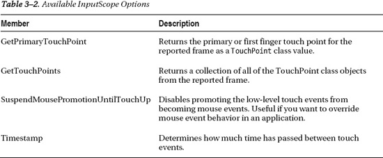
Unlike with the mouse events StylusPoint class, the TouchPoint class does not support PressureFactor values, so Opacity is not varied by pressure. The TouchPoint class does support a Size value for the touch action but the size resolves to a very small value regardless of whether drawing with a small finger or larger finger, making the Size value less useful. The following is the final Touch_FrameReported event handler:
void Touch_FrameReported(object sender, TouchFrameEventArgs e)

{

  foreach (TouchPoint p in e.GetTouchPoints(DrawCanvas))

  {

    if ((InDrawingMode) && (p.Action == TouchAction.Move))

    {

      Ellipse ellipse = new Ellipse();

      ellipse.SetValue(Canvas.LeftProperty, p.Position.X);

      ellipse.SetValue(Canvas.TopProperty, p.Position.Y);

      ellipse.Width = _touchRadius;

      ellipse.Height = _touchRadius;

      ellipse.IsHitTestVisible = false;

      ellipse.Stroke = ((ColorClass)ColorListBox.SelectedItem).ColorBrush;

      ellipse.Fill = ((ColorClass)ColorListBox.SelectedItem).ColorBrush;

      DrawCanvas.Children.Add(ellipse);

    }

  }

}
Notice that this code has an additional check on the Boolean variable InDrawingMode. The value of InDrawingMode is set to false when showing the color selector ColorListBox. This is because the Touch.FrameReported event fires no matter what control has focus. So without additional checks, selecting or scrolling colors would generate additional touch events on the DrawCanvas Canvas object. Raw touch with Touch.FrameReported is truly raw touch processing.
The mouse events have a nice benefit over Touch.FrameReported. The mouse events generate StylusPoint objects, which include a PressureFactor value instead of the TouchPoint objects for Touch.FrameReported. This allows varying the Opacity, for a better drawing experience. However, for other touch-related programming where Gestures or Manipulations cannot provide needed functionality, raw touch with Touch.FrameReported is recommended over mouse events
Multi-Touch with Raw Touch
One capability that Touch.FrameReported provides over mouse events is multi-touch capabilities via the TouchPoint class. The TouchPoint class has the following two members that allow tracking of state and history:
Action:Identifies whether the touch action isDown,Move, orUp.TouchDevice:Contains anIDthat represents the “finger” as it moves about the screen.
With these two properties it is possible to track the state of the touch as well as associated history as the user moves their finger around the screen. The MultiTouchwithRawTouch project is a simple program that tracks up to four touch actions by a user. Essentially you can place four fingers on the screen and watch the Rectangle objects follow your fingers on the screen. The XAML for the project is a generic page that has Rectangle objects dynamically added to a Canvas panel added to the default ContentPanel Grid. Listing 3–6 contains the source code for the code-behind file.
Listing 3–6. MultiTouchwithRawTouch MainPage.xaml.cs Code File
using System.Collections.Generic;

using System.Linq;

using System.Windows;

using System.Windows.Controls;

using System.Windows.Input;

using System.Windows.Media;

using System.Windows.Shapes;

using Microsoft.Phone.Controls;


namespace MultiTouchwithRawTouch

{

  public partial class MainPage : PhoneApplicationPage

  {

    List<TrackedTouchPoint> trackedTouchPoints = new List<TrackedTouchPoint>();


    // Constructor

    public MainPage()

    {

      InitializeComponent();


      Touch.FrameReported += new TouchFrameEventHandler(Touch_FrameReported);

    }


    void Touch_FrameReported(object sender, TouchFrameEventArgs e)

    {

      foreach (TouchPoint tp in e.GetTouchPoints(DrawCanvas))

      {

        tp.TouchDevice.

        TrackedTouchPoint ttp = null;

        var query = from point in trackedTouchPoints

                    where point.ID == tp.TouchDevice.Id

                    select point;

        if (query.Count() != 0)

          ttp = query.First();


        switch (tp.Action)

        {

          case TouchAction.Down: ttp = new TrackedTouchPoint();

            ttp.ID = tp.TouchDevice.Id;

            if (trackedTouchPoints.Count == 0)

            {

              ttp.IsPrimary = true;

              DrawCanvas.Children.Clear();

            }

            trackedTouchPoints.Add(ttp);

            ttp.Position = tp.Position;

            ttp.Draw(DrawCanvas);
break;
case TouchAction.Up: ttp.UnDraw(DrawCanvas);
trackedTouchPoints.Remove(ttp);
break;
default:
ttp.Position = tp.Position;
ttp.Draw(DrawCanvas);
break;
}
}
CleanUp(e.GetTouchPoints(DrawCanvas));
}
private void CleanUp(TouchPointCollection tpc)
{
List<int> ToDelete = new List<int>();
foreach (TrackedTouchPoint ttp in trackedTouchPoints)
{
var query = from point in tpc
where point.TouchDevice.Id == ttp.ID
select point;
if (query.Count() == 0)
ToDelete.Add(ttp.ID);
}
foreach (int i in ToDelete)
{
var query = from point in trackedTouchPoints
where point.ID == i
select point;
if (query.Count() != 0)
trackedTouchPoints.Remove(query.First());
}
if (trackedTouchPoints.Count == 0)
{
DrawCanvas.Children.Clear();
}
}
}
class TrackedTouchPoint
{
public TrackedTouchPoint()
{
Rect = new Rectangle() { Height = 50, Width = 50 };
Position = new Point(0, 0);
IsPrimary = false;
BrushColor = new SolidColorBrush(Colors.Yellow);
}
private Rectangle Rect { get; set; } public int ID { get; set; }
public Brush BrushColor
{
set
{
Rect.Fill = value;
}
}
public Point Position { get; set; }
public bool IsPrimary { get; set; }
public void Draw(Canvas canvas)
{
if (IsPrimary)
BrushColor = new SolidColorBrush(Colors.Blue);
Rect.SetValue(Canvas.LeftProperty, Position.X);
Rect.SetValue(Canvas.TopProperty, Position.Y);
if (Rect.Parent == null)
canvas.Children.Add(Rect);
}
public void UnDraw(Canvas canvas)
{
canvas.Children.Remove(Rect);
}
}
}
Raw touch with Touch.FrameReported gives full access to every touch event; however, it is cumbersome to work with when you just need to detect gestures or a set of gestures. For multi-touch programming Touch.FrameReported is not recommended. The next couple of sections cover gesture detection in the XNA Framework and Silverlight as well as manipulations, which are recommended for multi-touch.
Programming with Gestures
A gesture is a one or two finger action that is a pre-defined touch interaction. Gestures on Windows Phone are similar to gestures that are defined on Windows 7, iPhone, Android, or pretty much any other touch device. What makes gestures useful is their consistency, which means that they should not be altered or “enhanced” in a way that will confuse users.
I cover single-touch and raw touch in the previous section titled “Single-Point Touch,” but I did not speak to it in terms of gestures. Single-touch gestures consist of the following interactions:
- Tap: Select an object in a ListBox, touch to click a button, or text to navigate to another screen.
- Double Tap: Successive taps in a row that happen with a time duration such as one second and are therefore recognized as a double-tap, not two single-tap gestures.
- Pan: Use a single feature to move an object across the screen.
- Flick: Similar to a pan gesture except that the finger moves quickly across the screen, acceleration is detected, and the object moves with inertia relative to the amount of acceleration applied.
- Touch and Hold: Touch on an area of screen for a period of time, say a second, and a touch and hold gesture is detected. Used to open context menus.
The two-finger gestures are Pinch and Stretch. The pinch gesture consists of placing two fingers on the screen and moving them closer. Pinch is used to zoom out as well as to make an object smaller. The Stretch gesture consists of placing two fingers on the screen and moving them further away. Stretch is used to zoom in as well as to make an object larger. In the next two subsections I cover how to support gestures in Windows Phone Applications.
Multi-Touch with XNA Framework Libraries
The XNA Framework on Windows Phone includes the Microsoft.Xna.Framework.Input.Touch namespace. This is a non-graphical, non-rendering namespace, so it can be leveraged in both Silverlight and XNA Game Studio. The primary class for the namespace is the TouchPanel static class, which receives touch input that is automatically interpreted into a gesture for developers.
To process gestures, developers call TouchPanel.IsGestureAvailable to determine if a Gesture is pending. If one is, developers then call TouchPanel.ReadGesture. The Microsoft.Xna.Framework.Input.Touch namespace includes an enumeration named GestureType that identifies the supported gestures, DoubleTap, Flick, FreeDrag, HorizontalDrag, VerticalDrag, Hold, Pinch, and Tap.
The Chapter 3 project GesturesTouchPanelXNA demonstrates how simple it is to use the TouchPanel class to determine gestures. In the Initialize() method of Game1.cs, the code enables all possible gestures.
TouchPanel.EnabledGestures = GestureType.DoubleTap | GestureType.Flick |

  GestureType.FreeDrag | GestureType.Hold | GestureType.HorizontalDrag |

  GestureType.None | GestureType.Pinch | GestureType.PinchComplete |

  GestureType.Tap | GestureType.VerticalDrag | GestureType.DragComplete;
We want to draw text to the screen in the XNA Framework project so we right-click on the GesturesTouchPanelXNAContent Content project and select Add New Item…and then select Sprite Font. You can edit the FontName tag to be a different font name as long as you have rights to redistribute the font. It is changed to Pescadero because that is one of the fonts available for redistribution via XNA Game Studio. For more details on font redistribution, visit http://msdn.microsoft.com/en-us/library/bb447673.aspx. The project declares a SpriteFont object named spriteFontSegoeUIMono to represent the font.
In the LoadContent() method of Game1.cs, this code loads the font and defines a position in the middle of the screen to draw the font.
spriteFontSegoeUIMono = Content.Load<SpriteFont>("Segoe UI Mono");

spriteFontDrawLocation = new Vector2(graphics.GraphicsDevice.Viewport.Width / 2,

  graphics.GraphicsDevice.Viewport.Height / 2);
In the Update() method, here is the code to check for a gesture:
if (TouchPanel.IsGestureAvailable)

{

  gestureSample = TouchPanel.ReadGesture();

  gestureInfo = gestureSample.GestureType.ToString();

}
The gestureInfo variable is printed to the screen using the imported font with these lines of code in the Draw() method.
spriteBatch.Begin();

// Draw gesture info

string output = "Last Gesture: " + gestureInfo;


// Find the center of the string to center the text when outputted

Vector2 FontOrigin = spriteFontSegoeUIMono.MeasureString(output) / 2;

// Draw the string

spriteBatch.DrawString(spriteFontSegoeUIMono, output, spriteFontDrawLocation,

  Color.LightGreen,0, FontOrigin, 1.0f, SpriteEffects.None, 0.5f);

spriteBatch.End();
Run the application on a device and gesture on the screen to see the gesture recognized and the name of the gesture action drawn onscreen. Now that we have an easy way to detect a gesture, let's use it to do something useful.
The GestureSample class provides six properties to provide useful information regarding the gesture, GestureType, Timestamp, Position, Position2, Delta, and Delta2. You know what GestureType does from the discussion in the preceding paragraphs. Timestamp indicates the time of the gesture sample reading. The Timestamp values are continuous for readings to they can be subtracted to determine how much time passed between readings. The other four values are Vector2 values related to the position of the finger on the screen. Position represents the first finger. Position2 represents the second finger if a two-finger gesture. The Delta and Delta2 values are like Timestamp, in that they indicate the changes in finger position relative to the last finger position, not between fingers if a multi-touch gesture. Table 3–3 relates gestures to the applicable fields with relevant notes.

Debug info is added to write out the data from the GestureSample instance named gestureSample to help with development. The following is an example from the beginning of a Pinch gesture:
gesture Type:      Pinch

gesture Timestamp: 03:27:37.3210000

gesture Position:  {X:425.2747 Y:287.3394}

gesture Position2: {X:523.077 Y:366.6055}

gesture Delta:     {X:0 Y:0}

gesture Delta2:    {X:0 Y:0}
A short expanding Pinch gesture results in about 30 gesture samples over just less than half a second, providing a rich set of data to apply to objects as a result of user touches. Run the sample and perform gestures on blank portions of the screen to see how position and delta values change.
To make the sample more interesting stickman figure manipulation is added to the GesturesTouchPanelXNA project. The stickman figure responds to Hold, Flick, Drag, and Pinch gestures. Figure 3–9 shows the simple UI but you will want to run this on a device to try out the supported gestures.
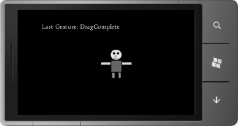
Figure 3–9. Multi-Touch with the XNA Framework UI
If you tap and hold (Hold GestureType) on the stickman, the figure rotates 90 degrees. If the stickman is flicked (Flick GestureType), the stickman will bounce around the screen and will eventually slow down. Tap on the stickman to stop movement. Finally, drag (FreeDrag GestureType) to slide the stickman around the screen.
There is a little bit of XNA Framework development in the sample to create a basic GameObject class to represent the stickman sprite. This keeps the game code clean without using a bunch of member variables to track state in the Game1.cs file. Listing 3–7 shows the GameObject class.
Listing 3–7. GameObject.cs Code File
using Microsoft.Xna.Framework;

using Microsoft.Xna.Framework.Graphics;


namespace GesturesTouchPanelXNA

{

  class GameObject

  {

    private const float _minScale = .4f;

    private const float _maxScale = 6f;

    private const float _friction = .7f;

    private const float _bounceVelocity = .9f;


    private float _scale = 1f;

    private Vector2 _velocity;

    private Vector2 _position;


    public GameObject(Texture2D gameObjectTexture)

    {

      Rotation = 0f;

      Position = Vector2.Zero;

      SpriteTexture = gameObjectTexture;

      Center = new Vector2(SpriteTexture.Width / 2, SpriteTexture.Height / 2);
Velocity = Vector2.Zero;
TintColor = Color.White;
Selected = false;
}
public Texture2D SpriteTexture { get; set; }
public Vector2 Center { get; set; }
public float Rotation { get; set; }
public Rectangle TouchArea { get; set; }
public Color TintColor { get; set; }
public bool Selected { get; set; }
public float Scale
{
get { return _scale; }
set
{
_scale = MathHelper.Clamp(value, _minScale, _maxScale);
}
}
public Vector2 Position
{ get { return _position; }
set { _position = value ; } //Move position to Center.
}
public Vector2 Velocity
{
get {return _velocity;}
set { _velocity = value; }
}
public Rectangle BoundingBox
{
get
{
Rectangle rect =
new Rectangle((int)(Position.X - SpriteTexture.Width / 2 * Scale),
(int)(Position.Y - SpriteTexture.Height / 2 * Scale),
(int)(SpriteTexture.Width * Scale),
(int)(SpriteTexture.Height * Scale));
//Increase the touch target a bit
rect.Inflate(10, 10);
return rect;
}
}
public void Update(GameTime gameTime, Rectangle displayBounds)
{
//apply scale for pinch / zoom gesture
float halfWidth = (SpriteTexture.Width * Scale) / 2f;
float halfHeight = (SpriteTexture.Height * Scale) / 2f;
// apply friction to slow down movement for simple physics when flicked
Velocity *= 1f - (_friction * (float)gameTime.ElapsedGameTime.TotalSeconds); // Calculate position
//position = velocity * time
//TotalSeconds is the amount of time since last update in seconds
Position += Velocity * (float)gameTime.ElapsedGameTime.TotalSeconds;
// Apply "bounce" if sprite approaches screen bounds
if (Position.Y < displayBounds.Top + halfHeight)
{
_position.Y = displayBounds.Top + halfHeight;
_velocity.Y *= -_bounceVelocity;
}
if (Position.Y > displayBounds.Bottom - halfHeight)
{
_position.Y = displayBounds.Bottom - halfHeight;
_velocity.Y *= -_bounceVelocity;
} if (Position.X < displayBounds.Left + halfWidth)
{
_position.X = displayBounds.Left + halfWidth;
_velocity.X *= -_bounceVelocity;
}
if (Position.X > displayBounds.Right - halfWidth)
{
_position.X = displayBounds.Right - halfWidth;
_velocity.X *= -_bounceVelocity;
}
}
public void Draw(SpriteBatch spriteBatch)
{
spriteBatch.Draw(SpriteTexture, Position, null, TintColor, Rotation,
Center, Scale,
SpriteEffects.None,0);
}
}
}
The vast majority of the GameObject class is basic math calculations for checking screen boundaries, velocity, position, and so on. The one item to point out is the handy MathHelper static class that includes numerous helpful methods. The Clamp method is used to limit the zooming via the Pinch GestureType to be between a min and max scale value.
The other interesting code is the ProcessTouchInput() method in Game1.cs that is called in the Update() method. The method checks for touches first in order to determine if the stickman was touched on screen. To perform the check, each touch is converted to a Point object mapped into the screen coordinates. Next, we create a Rectangle object that encapsulates the stickman. The Rectangle.Contains method is passed in the Point object that represents the touch to determine if the touch was within the bounding box of the stickman. If the Point object is within the bounds of the Rectangle object, Selected is set to true on the StickMan sprite and gestures are applied. Otherwise, if a gesture is performed outside of the stickman, the gesture info is displayed to the screen as before but the StickMan sprite is not affected. The following is the code to determine selection:
TouchCollection touches = TouchPanel.GetState();if ((touches.Count > 0) && (touches[0].State == TouchLocationState.Pressed))
{
// map touch to a Point object to hit test
Point touchPoint = new Point((int)touches[0].Position.X,
(int)touches[0].Position.Y);
if (StickManGameObject.BoundingBox.Contains(touchPoint))
{
StickManGameObject.Selected = true;
StickManGameObject.Velocity = Vector2.Zero;
}
}
A switch statement is added to the while (TouchPanel.IsGestureAvailable) loop. As a GestureType is identified, it is applied to the StrawMan sprite. The switch statement is shown in Listing 3–8.
Listing 3–8. ProcessInput Method GestureType Switch Statement
if (StickManGameObject.Selected)

{

  switch (gestureSample.GestureType)

  {

    case GestureType.Hold:

      StickManGameObject.Rotation += MathHelper.Pi;

      break;

    case GestureType.FreeDrag:

      StickManGameObject.Position += gestureSample.Delta;

      break;

    case GestureType.Flick:

      StickManGameObject.Velocity = gestureSample.Delta;

      break;

    case GestureType.Pinch:

      Vector2 FirstFingerCurrentPosition = gestureSample.Position;

      Vector2 SecondFingerCurrentPosition = gestureSample.Position2;

      Vector2 FirstFingerPreviousPosition = FirstFingerCurrentPosition -

              gestureSample.Delta;

      Vector2 SecondFingerPreviousPosition = SecondFingerCurrentPosition -

              gestureSample.Delta2;

      //Calculate distance between fingers for the current and

      //previous finger positions.  Use it as a ration to

      //scale object.  Can have positive and negative scale.

      float CurentPositionFingerDistance = Vector2.Distance(

        FirstFingerCurrentPosition, SecondFingerCurrentPosition);

      float PreviousPositionFingerDistance = Vector2.Distance(

        FirstFingerPreviousPosition, SecondFingerPreviousPosition);


      float zoomDelta = (CurentPositionFingerDistance -

                          PreviousPositionFingerDistance) * .03f;

      StickManGameObject.Scale += zoomDelta;

      break;

  }

}
For the GestureType.Hold gesture, the StickMan's Rotation property on the sprite is altered by MathHelper.PiOver2 radians, which is equal to 90 degrees. For the GestureType.FreeDrag gesture, the StickMan's Position property is updated by the Delta value, which is a Vector2 in the direction and magnitude of movement since the last time a gesture sample was provided. For GestureType.Flick, the StickMan's Velocity is updated by the Delta as well, which in this case represents a flick speed that is added.
The GestureType.Pinch gesture requires a bit more calculation, but it is fairly straightforward. Essentially, the distance between fingers in screen coordinates is calculated for the current finger position and previous finger position. The differences are used to calculate scale factor. Increasing finger distance is a positive scale factor. Decreasing finger distance is a negative scale factor. If the distance greatly increases (either to be bigger or smaller), that determines the size of the scale factor.
Touch input and Gestures are a key component to game development for Windows Phone. This section covered a lot of ground from gesture recognition to applying gestures to a game object, taking advantage of the gesture capabilities available in the XNA Framework libraries. We will now cover how to work with gestures in Silverlight.
Multi-Touch with Silverlight
We can take the information above regarding XNA Framework multi-touch and apply it to Silverlight. Because Silverlight and XNA Framework share the same application model, you can share non-drawing libraries across programming models. This is demonstrated in the GesturesTouchPanelSilverlight project. To get started, add a reference to the Microsoft.Xna.Framework and Microsoft.Xna.Framework.Input.Touch namespaces.
In the MainPage() constructor in MainPage.xaml.cs, add the following code to enable Gestures, just as before:
TouchPanel.EnabledGestures = GestureType.DoubleTap | GestureType.Flick |

        GestureType.FreeDrag | GestureType.Hold | GestureType.HorizontalDrag |

        GestureType.None | GestureType.Pinch | GestureType.PinchComplete |

        GestureType.Tap | GestureType.VerticalDrag | GestureType.DragComplete;
In XNA Game Studio, the game loop Update method is called 30 times a second so it is a single convenient place to capture touch input. In Silverlight there isn't a game loop. A polling loop could be simulated with a DispatcherTimer that fires every 1000/30 milliseconds. This is the cleanest approach, because it exactly simulates how the XNA Framework works.
Another method is to hook into the mouse or manipulation events. I cover the manipulation events in the next section so we use the mouse events instead. This will work fine most of the time, but some gesture events fire in MouseLeftButtonDown and MouseButtonUp as well as MouseMove so you have to be careful if it causes you a bug if you are just tracking events in MouseMove, and so on. The following is the code to capture gesture events in Silverlight mouse events:
private void PhoneApplicationPage_MouseLeftButtonDown(object sender, MouseButtonEventArgs e)

{

  while (TouchPanel.IsGestureAvailable)

  {

    GestureActionsListBox.Items.Add("LeftBtnDown "+TouchPanel.ReadGesture().GestureType.ToString());


  }

}
private void PhoneApplicationPage_MouseLeftButtonUp(object sender, MouseButtonEventArgs e)
{
while (TouchPanel.IsGestureAvailable)
{
GestureActionsListBox.Items.Add("LeftBtnUp " + TouchPanel.ReadGesture().GestureType.ToString());
}
}
private void PhoneApplicationPage_MouseMove(object sender, MouseEventArgs e)
{
while (TouchPanel.IsGestureAvailable)
{
GestureActionsListBox.Items.Add("MouseMove " +
TouchPanel.ReadGesture().GestureType.ToString());
}
}
Once the gestures are detected in the mouse events, you can perform similar programming using a Canvas panel as with the XNA Framework ample to react to gestures. One additional item to consider when comparing the XNA Framework and Silverlight is the coordinate system. In the XNA Framework, all objects are absolutely positioned relative to the upper left hand corner so the math to calculate position is straightforward. In Silverlight, objects can be placed within containers. For example, a Rectangle can have margin top and left margin of 10,10, but be contained within a Grid that has margin of 100,100 relative to the screen so coordinate mapping is necessary to translate the touch location to an actual control position.
Another method to detect gestures in Silverlight is available within the Silverlight for Windows Phone Toolkit at Silverlight.codeplex.com. The toolkit includes the GestureService/GestureListener components to detect gestures, so you will want to download the toolkit to test out the sample
Once the Silverlight for Windows Phone Toolkit is installed, browse to the toolkit library and add a reference. On my system it is located here: C:Program Files (x86)Microsoft SDKsWindows Phonev7.0ToolkitNov10Bin. The GesturesSilverlightToolkit project demonstrates how to use the GestureListener control. The toolkit library is added as a reference and made available in MainPage.xaml via an xml namespace import:
xmlns:toolkit="clr-namespace:Microsoft.Phone.Controls;assembly=

Microsoft.Phone.Controls.Toolkit"
A Rectangle object containing a GestureListener control is added to the ContentPanel Grid:
<toolkit:GestureService.GestureListener>

  <toolkit:GestureListener />

</toolkit:GestureService.GestureListener>
Figure 3–10 shows the events available on the GestureListener.

Figure 3–10. GestureListener events
An event handler is added for all the possible supported gestures, Tap, DoubleTap, Drag, Flick, TapAndHold, and Pinch to the GesturesSilverlightToolkit project to allow you to explore the events. Figure 3–11 shows the test UI.

Figure 3–11. Multi-Touch with the XNA Framework UI
An important item to note, each event has unique EventArgs to provide the information developers need to apply the gesture to objects. As an example, the FlickGestureEventArgs class includes Angle, Direction, GetPosition, Handled, HorizontalVelocity, and VerticalVelocity members. The properties are more tailored toward Silverlight development, which may simplify gesture processing over using the XNA Framework libraries.
This concludes the discussion of gesture processing. The next section covers manipulation events.
Programming with Manipulation Events
Manipulations permit more complex interactions. They have two primary characteristics: Manipulations consists of multiple gestures that appear to happen simultaneously. The other characteristic is that manipulations consist of a set of transforms resulting from the user touch actions. The Manipulation events are very helpful because they interpret the user touch interaction into a set of transforms like translate and scale that you as the developer can apply to objects onscreen.
Windows Presentation Foundation 4.0 introduced Manipulation events to provide a high-level touch programming model that simplifies touch programming when compared to using low-level raw touch input. A subset of the manipulation events is available in Silverlight for Windows Phone with some differences. WPF manipulation events support translation, scaling, and rotation. Silverlight for Windows Phone does not include rotation.
Manipulation events do not distinguish between fingers. The events interpret finger movement into translation and scaling as well as an indication of velocity to implement physics.
Windows Phone includes three manipulation events: ManipulationStarted, ManipulationDelta, and ManipulationCompleted defined on the UIElement base class. Each manipulation event includes a custom EventArgs class with the following members in common:
e.OriginalSource:The original object that raised the event.e.ManipulationContainer:The container object or panel that defines the coordinate system for the manipulation. This property will stay consistent through all three events.e.ManipulationOrigin:The point from which the manipulation originated. Indicates the location of the finger relative to theManipulationContainerobject. For two-finger manipulations, theManipulationOriginrepresents roughly the center point between the two fingers.
The events include unique EventArgs members as well, listed in the following:
ManipulationStarted:TheManipulationStartedEventArgsclass includes aCompletemethod that completes the manipulation without inertia, and aHandledproperty to indicate that the routed event is handled so that other controls don't attempt to handle the event again.ManipulationDelta:TheManipulationDeltaEventArgsclass includes aCompletemethod. TheIsInertialmethod indicates whether theDeltaevents has occurring during inertia. Other properties areDeltaManipulationandCumulativeManipulation, which represent the discrete (delta) and cumulative changes sinceManipulationStartedresulting from the manipulation. The otherEventArgsproperty isVelocities, which indicates the most recent rate of change for the manipulation.ManipulationCompleted:TheManipulationCompletedEventArgsinclude aFinalVelocitiesandTotalManipulationproperties. It also includes aHandledandIsInertialproperties.
As we saw before with gesture development there is one “started” event followed by zero or more ManipulationDelta events, and then a ManipulationCompleted “completed” event. To test manipulations, we created the ManipulationEvents project using the StickMan sprite from the GesturesTouchPanelXNA project. Figure 3–12 shows the UI.
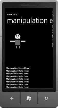
Figure 3–12. Manipulations test app UI
The project implements drag and scale via the ManipulationsDelta event. Here is the code for the ManipulationsDelta event.
private void StickManImage_ManipulationDelta(object sender,

  ManipulationDeltaEventArgs e)

{

  ReportEvent("Manipulation Delta Event: ");

  Image image = sender as Image;

  CompositeTransform compositeTransform =

    image.RenderTransform as CompositeTransform;


  if ((e.DeltaManipulation.Scale.X > 0) || (e.DeltaManipulation.Scale.Y > 0))

  {

    double ScaleValue = Math.Max(e.DeltaManipulation.Scale.X,

      e.DeltaManipulation.Scale.Y);

    System.Diagnostics.Debug.WriteLine("Scale Value: " +

      ScaleValue.ToString());


    //Limit how large

    if ((compositeTransform.ScaleX <= 4d) || (ScaleValue < 1d))

    {

      compositeTransform.ScaleX *= ScaleValue;
compositeTransform.ScaleY *= ScaleValue;
}
}
System.Diagnostics.Debug.WriteLine("compositeTransform.ScaleX: " +
compositeTransform.ScaleX);
System.Diagnostics.Debug.WriteLine("compositeTransform.ScaleY: " +
compositeTransform.ScaleY);
compositeTransform.TranslateX += e.DeltaManipulation.Translation.X;
compositeTransform.TranslateY += e.DeltaManipulation.Translation.Y;
e.Handled = true;
}
The code modifies a CompositeTransform based on the DeltaManipulation values, Scale for Pinch gestures and Translation for movement. The CompositeTransform is declared in the XAML for the StickMan Image tag, as shown in the following:
<Image x:Name="StickManImage" Source="/images/StickMan.png"

   ManipulationCompleted="StickManImage_ManipulationCompleted"

   ManipulationDelta="StickManImage_ManipulationDelta"

    ManipulationStarted="StickManImage_ManipulationStarted">

<Image.RenderTransform>

    <CompositeTransform />

</Image.RenderTransform>

</Image>
The Silverlight for Windows Phone Toolkit GestureListener control is the preferred method for detecting gestures in Silverlight for Windows Phone. Manipulation events should be a second or third choice if for some reason the GestureListener or XNA Framework libraries do not suit your needs. For non-gesture detection multi-touch development, the manipulation events are recommended. Let's now shift gears to discuss other forms of application input on Windows Phone 7.
Accelerometer
As far as fun goes, the accelerometer can be an entertaining and engaging method of input, especially for game development with XNA Game Studio or Silverlight. We all have seen the car racing games on mobile phone or mobile gaming devices where the user is tilting the device like a steering wheel. The next section covers how to work with the Accelerometer sensor.
Understanding How It Works
The Accelerometer sensor detects acceleration in all three axes, X, Y, Z, to form a 3D vector. You may wonder in what direction and magnitude does the vector point? Collect a few Accelerometer readings using this line of code:
      System.Diagnostics.Debug.WriteLine(AccelerometerHelper

.Current2DAcceleration.ToString());
The following are a few samples from the Output window when debugging:
{X:0.351 Y:-0.002 Z:0.949} (Magnatude is approximately 1.02)

{X:0.401 Y:0.044 Z:0.984} (Magnatude is approximately 1.06)

{X:0.378 Y:0.04 Z:1.023} (Magnatude is approximately 1.09)

{X:0.386 Y:0.022 Z:0.992} (Magnatude is approximately 1.06)

{X:0.409 Y:0.03 Z:0.992} (Magnatude is approximately 1.07)
You can calculate the magnitude of the vector using the Pythagorean Theorem, which is the Sqrt(X2+Y2+Z2) = magnitude of the vector. The value should be about one but as you can see from the above samples, it can vary by location or could possibly be an error deviation. Either way, this is why applications like a level suggest that you calibrate the level against a known flat surface before using the virtual level.
If you run the application in the emulator, this reading is returned every time: {X:0 Y:0 Z:-1}, unless you use the accelerometer simulation tool available in the Winodows Phone OS 7.1 SDK to simulate acceleration.
Holding the phone flat in my unsteady hand yields similar values with Z near one and X, and Y near zero.
{X:0.039 Y:0.072 Z:-1.019}

{X:0.069 Y:0.099 Z:-1.047}

{X:0.012 Y:0.056 Z:-1.008}

{X:0.016 Y:0.068 Z:-1.019}
This suggests that the vector is oriented to point towards the center of the earth, which for the above readings is the bottom of the phone or a negative Z when the phone is lying flat on its back. Flipping the phone in my hand yields the following values:
{X:-0.043 Y:0.08 Z:1.019}

{X:-0.069 Y:0.111 Z:1.093}

{X:-0.069 Y:0.099 Z:1.093}

{X:-0.039 Y:0.107 Z:1.031}
This time the vector is pointing out from the glass toward the ground, because the phone is lying face down. This information is useful if you need to determine how the phone is oriented in the users hand when say taking a photograph.
Figure 3–13 shows the accelerometer coordinate system. This is important because developers must translate readings into the coordinate system for the application.
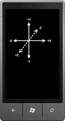
Figure 3–13. Accelorometer fixed coordinate system
As an example, in the XNA Framework, the default 2D coordinate system has positive Y going down, not up, so you cannot just take the Y component of acceleration and apply it to the Y value for a game object in 2D XNA.
![]() Note The default coordinate system for 3D in the XNA Framework has positive Y going up. Chapter 8 covers 3D XNA Game Studio development.
Note The default coordinate system for 3D in the XNA Framework has positive Y going up. Chapter 8 covers 3D XNA Game Studio development.
With this background in hand, the next section covers development with the accelerometer sensor.
Programming with the Accelerometer
Accessing the Accelerometer sensor is pretty straightforward. We start with an XNA project, adding a reference to the Microsoft.Devices.Sensors assembly, and declaring instance of the Accelerometer class. In the Game1.Initialize() method, create an instance of the Accelerometer and call the Start() method to generate readings.
Create an event handler for ReadingChanged as well. The following is the code to create the event handler:
accelerometer = new Accelerometer();

accelerometer.Start();

accelerometer.ReadingChanged +=

  new EventHandler<AccelerometerReadingEventArgs>(accelerometer_ReadingChanged);
The accelerometer_ReadingChanged event handler event arguments AccelerometerReadingEventArgs class exposes acceleration in three dimensions via the X, Y, and Z member variables of type double. There is also a TimeStamp variable to allow measurement of acceleration changes over time.
A private member Vector3 variable named AccelerometerTemp is added to the Game1 class to collect the reading so that the code in the event handler does not have to new up a Vector3 each time a reading is collected. We create a helper static class named AccelerometerHelper that takes the accelerometer reading and assigns it to a Vector3 property named Current3DAcceleration. The following is the ReadingChanged event handler:
private Vector3 AccelerometerTemp = new Vector3();

void accelerometer_ReadingChanged(object sender, AccelerometerReadingEventArgs e)

{

  //

  AccelerometerTemp.X = (float)e.X;

  AccelerometerTemp.Y = (float)e.Y;

  AccelerometerTemp.Z = (float)e.Z;


  AccelerometerHelper.Current3DAcceleration  = AccelerometerTemp;

  AccelerometerHelper.CurrentTimeStamp = e.Timestamp;

}
The AccelerometerHelper class takes the Vector3 and parses the values up in the “setter” function for the Current3DAcceleration property into the class members listed in Figure 3–14.
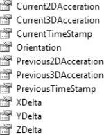
Figure 3–14. AccelerometerHelper class members
Most of the code in the AccelerometerHelper class is properties and private member variables to hold values. Private backing variables are optional with the {get ; set ;} construct in C# but we use them here in order for all other member variables to be derived from just setting the Current3DAcceleration property. Listing 3–9 has the code for the AccelerometerHelper class.
Listing 3–9. AccelerometerHelper Class Code File
using System;

using System.Collections.Generic;

using System.Linq;

using System.Text;

using Microsoft.Xna.Framework;


namespace AccelerometerInputXNA

{

  static public class  AccelerometerHelper

  {

    static private Vector3 _current3DAcceleration;

    static public Vector3 Current3DAcceleration

    {

      get

      {

        return _current3DAcceleration;

      }

      set

      {

        //Set previous to "old" current 3D acceleration

        _previous3DAcceleration = _current3DAcceleration;


        //Update current 3D acceleration

        //Take into account screen orientation

        //when assigning values

        switch (Orientation)

        {

          case DisplayOrientation.LandscapeLeft:

            _current3DAcceleration.X = -value.Y;

            _current3DAcceleration.Y = -value.X;

            _current3DAcceleration.Z = -value.Z;

            break;

          case DisplayOrientation.LandscapeRight:

            _current3DAcceleration.X = value.Y;

            _current3DAcceleration.Y = value.X;

            _current3DAcceleration.Z = value.Z;

            break;

          case DisplayOrientation.Portrait:

            _current3DAcceleration.X = value.X;

            _current3DAcceleration.Y = value.Y;

            _current3DAcceleration.Z = value.Z;

            break;

        }
//Update current 2D acceleration
_current2DAcceleration.X = _current3DAcceleration.X;
_current2DAcceleration.Y = _current3DAcceleration.Y;
//Update previous 2D acceleration
_previous2DAcceleration.X = _previous3DAcceleration.X;
_previous2DAcceleration.Y = _previous3DAcceleration.Y;
//Update deltas
_xDelta = _current3DAcceleration.X - _previous3DAcceleration.X;
_yDelta = _current3DAcceleration.Y - _previous3DAcceleration.Y;
_zDelta = _current3DAcceleration.Z - _previous3DAcceleration.Z;
}
}
static private Vector2 _current2DAcceleration;
static public Vector2 Current2DAcceleration
{
get
{
return _current2DAcceleration;
}
}
static private DateTimeOffset _currentTimeStamp;
static public DateTimeOffset CurrentTimeStamp
{
get
{
return _currentTimeStamp;
}
set
{
_previousTimeStamp = _currentTimeStamp;
_currentTimeStamp = value;
}
}
static private Vector3 _previous3DAcceleration;
static public Vector3 Previous3DAcceleration
{ get { return _previous3DAcceleration; } }
static private Vector2 _previous2DAcceleration;
static public Vector2 Previous2DAcceleration
{ get { return _previous2DAcceleration; } }
static private DateTimeOffset _previousTimeStamp;
static public DateTimeOffset PreviousTimeStamp
{ get { return _previousTimeStamp; } }
static private double _xDelta ;
static public double XDelta { get { return _xDelta;} }
static private double _yDelta; static public double YDelta { get { return _yDelta; } }
static private double _zDelta;
static public double ZDelta { get { return _zDelta; } }
public static DisplayOrientation Orientation { get; set; }
}
}
Notice in the setter function for the Current3DAcceleration property, there is a switch statement that flips the sign as needed based on device orientation, whether landscape left or landscape right, because the accelerometer coordinate system is fixed. This ensures that behavior is consistent when the XNA Framework flips the screen based on how the user is holding the device
To test the helper class, we copy over the GameObject class and assets, StickMan and the font, from the GesturesTouchPanelXNA project as well as the code to load up the assets and draw on the screen. The gesture code is not copied over since the input for this project is the Accelerometer. As before, the Game1.Update() method in the game loop is the place to handle input and apply it to objects. This line of code is added to the Update method to apply acceleration to the StickMan GameObject instance:
StickManGameObject.Velocity += AccelerometerHelper.Current2DAcceleration;
Run the application and the application behaves as expected: tilt the phone left, and the StickMan slides left, and vice versa when holding the phone in landscape orientation. If you tilt the phone up far enough, the screen flips to either DisplayOrientation.LandscapeLeft or DisplayOrientation.LandscapeRight and the behavior remains consistent.
The main issue with this calculation of just adding the Current2DAcceleration to the StickMan's velocity results in a very slow acceleration. This can be easily remedied by scaling the value like this
StickManGameObject.Velocity +=30* AccelerometerHelper.Current2DAcceleration;
The UI “feels” much better with this value and is more fun to interact with. Depending on the game object's desired behavior, you could create a ratchet effect by having fixed positions when the accelerometer values are between discrete values instead of the smooth application of accelerometer values to position in this code sample.
The Accelerometer sensor works equally well in Silverlight. The difference is mapping Accelerometer sensor changes to X/Y position values directly (instead of applying Vectors) using a CompositeTransform object just like what was done in the Silverlight sample with Manipulations in the previous section on multi-touch. Next up is the Location sensor.
Accelerometer Simulation
In the Windows Phone OS 7.1 development tools, the Windows Phone Emulator now exposes the ability to simulate the accelerometer when running your code in the emulator, a productivity boon for developers.
To test this out, I run the AccelerometerInputXNA sample in the Windows Phone Emulator. Figure 3-15 shows the tool.
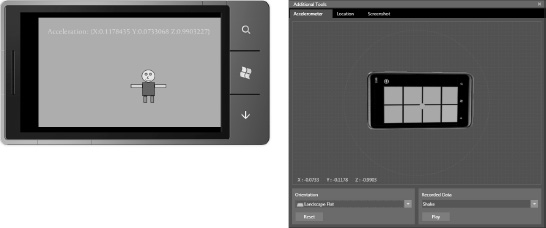
Figure 3–15. Windows Phone accelerometer simulator
As you can see in the UI, a virtual phone is presented in a window next to the emulator. As you move the mouse while dragging the virtual phone, it updates the readings sent to the simulated accelerometer sensor.
Notice that the bottom part of the simulator allows you to set the orientation of the device to match how the application is expected to work. In this case, it is set to Landscape Flat, which matches the orientation of the emulator. Make sure the emulator orientation and the simulator orientation match for best results.
You can also send a “Shake” to the emulator via the other option at the bottom of the simulation control UI. The accelerometer simulation tool provides a very easy-to-use interface to help you get the most out of your accelerometer-based applications.
In the next section, I cover the location sensor as well as the simulation tool to help you build great location-based application with the emulator without having to walk-around with your PC while debugging.
Location
The location sensor is a very useful capability, given that mobile devices are generally on the go with their owner. Location provides context for applications that can make life easier on the user by automatically adjusting for the user's current location. A great example is the Search button on the phone. Enter or speak a keyword and click search. The local tab finds relevant items nearby. So a search for “Starbucks” gives the user exactly what they want on the local tab—which café is closest.
Understanding How It Works
The location sensor is a service that can use cell tower locations, wireless access point locations, and GPS to determine a user's location with varying degree of accuracy and power consumption.
Determining location with GPS is highly accurate, but it takes a while to spin up the GPS, and it consumes relatively more battery. Determining location using cell tower location is very fast, doesn't consume additional battery, but may not be accurate depending on how many cell towers are in range and their relative distance from each other in relation to the phone. Determining location with wireless access points can be accurate depending on how many wireless access points are in range and their relative position. If only one wireless access point is available location data will have a large error ring. Turning on Wi-Fi can consume additional battery power as well.
Programming with Location
You may try to guess that the Location namespace is in the Microsoft.Devices.Sensors namespace, but that would not be correct. It is located in the System.Device.Location namespace. The primary class for location is the GeoCoordinateWatcher class with the following class members:
DesiredAccuracy:Can have a value ofGeoPositionAccuracy.DefaultorGeoPositionAccuracy.High. The latter value forces the use of GPS, which can delay readings and consume battery. Use with care.MovementThreshold:This has a type of double. It indicates how far you have to move in order to generate a location reading in meters.Permission:Level of access to the location service.- Position: Latest position obtained from location service.
PositionChanged:Event that fires when a new position is available.- Start: Starts location data acquisition from the location service.
Status:Current status of the location service.StatusChanged:Event that fires when the status of the location changes.Stop:Stops location data acquisition from the location service.TryStart:Attempts to start location data acquisition with a timeout parameter passed in. The method returns false if the timeout expires before data is acquired. This call is synchronous and will block the thread it is called on – call on a background thread.
For this section topic on forward for the rest of the chapter, we start a new solution named Ch03_HandlingInput_Part2. The sample in that solution for this section is titled LocationSensorSilverlight. In the MainPage() constructor for the LocationSensorSilverlight project, the LocationService is instantiated and events for PositionChanged and StatusChanged are wired up. Here is the code:
LocationService = new GeoCoordinateWatcher();

LocationService.PositionChanged +=

  new EventHandler<GeoPositionChangedEventArgs<GeoCoordinate>>

    (LocationSensor_PositionChanged);


LocationService.StatusChanged +=

  new EventHandler<GeoPositionStatusChangedEventArgs>

    (LocationSensor_StatusChanged);
The rest of the application is just UI to display the LocationService information. The code uses the Bing Maps Map object to center the map on the user's current location. Here is the event handler to plot and zoom in on the map a bit:
private void PlotLocation_Click(object sender, EventArgs e)

{

  BingMap.Center = LocationService.Position.Location;

  BingMap.ZoomLevel = 15;

}
For more information we cover the Bing Maps control in detail in Chapter 5, but the most important property for the Map control is to set the CredentialsProvider key in XAML.
![]() Note Obtain a free
Note Obtain a free CredentialsProvider developer key from the Bing Maps account management web site located at www.bingmapsportal.com.
The UI implements the Application Bar to start and stop the Location Service as well as plot current location. The Application Bar also has a menu item to change the location accuracy. It is not possible to change accuracy after instantiating the GeoCoordinateWatcher variable. You have to instantiate a new GeoCoordinateWatcher variable and wire-up the event handlers again. Here is the code that handles this:
private void SetAccuracy_Click(object sender, EventArgs e)

{

  if (LocationService.DesiredAccuracy == GeoPositionAccuracy.Default)

    if (MessageBox.Show(

      "Current Accuracy is Default.  Change accuracy to High?"

      +"This may take some time and will consume additional battery power.",

      "Change Location Accuracy", MessageBoxButton.OKCancel)

      == MessageBoxResult.OK)

    {

      LocationService.Dispose();

      LocationService = new GeoCoordinateWatcher(GeoPositionAccuracy.High);

      LocationService.PositionChanged +=

    new EventHandler<GeoPositionChangedEventArgs<GeoCoordinate>>

      (LocationSensor_PositionChanged);
LocationService.StatusChanged +=
new EventHandler<GeoPositionStatusChangedEventArgs>
(LocationSensor_StatusChanged);
}
else
if (MessageBox.Show(
"Current Accuracy is High. Change accuracy to Default?"+
"This wll be faster but will reduce accuracy.",
"Change Location Accuracy", MessageBoxButton.OKCancel)
== MessageBoxResult.OK)
{
LocationService.Dispose();
LocationService =
new GeoCoordinateWatcher(GeoPositionAccuracy.Default);
LocationService.PositionChanged +=
new EventHandler<GeoPositionChangedEventArgs<GeoCoordinate>>
(LocationSensor_PositionChanged);
LocationService.StatusChanged +=
new EventHandler<GeoPositionStatusChangedEventArgs>
(LocationSensor_StatusChanged);
}
}
The XAML for the MainPage class implements a simple status panel that displays Location Service data. The code also uses the Silverlight Toolkit GestureListener to allow the user to drag the status panel over the map. Here is the markup:
<Border x:Name="LocationStatusPanel" HorizontalAlignment="Left"  VerticalAlignment="Top"

  Background="#96000000" Padding="2" >

  <toolkit:GestureService.GestureListener>

    <toolkit:GestureListener  DragDelta="GestureListener_DragDelta"/>

  </toolkit:GestureService.GestureListener>

  <Border.RenderTransform>

    <CompositeTransform/>

  </Border.RenderTransform>

    <StackPanel Orientation="Horizontal" Width="200" >

…Xaml for TextBoxes here.

    </StackPanel>

</Border>
Here is the GestureListener_DragDelta event handler code that repositions based on the user dragging the status panel.
private void GestureListener_DragDelta(object sender, DragDeltaGestureEventArgs e)

{

  Border border = sender as Border;

  CompositeTransform compositeTransform = border.RenderTransform as CompositeTransform;

  compositeTransform.TranslateX += e.HorizontalChange;

  compositeTransform.TranslateY += e.VerticalChange;

  e.Handled = true;

}
Windows Phone Emulator Location Simulation
Also in the Windows Phone 7.1 OS development tools, the Windows Phone Emulator includes another simulation tool, this time for location. This simulator is a very powerful and useful debugging and testing tool with the ability to set location as well as create a set of points for playback to ensure more consistent testing. Figure 3-16 shows the location UI with the emulator located where the plot point was added to the map on the simulator UI.
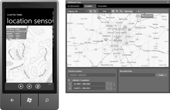
Figure 3–16. Windows Phone location simulator
Notice in the top left you can search for a location; in this case, it's Atlanta, GA. The location simulator has three points plotted roughly along Interstate 85 in Atlanta, GA. You place points by clicking on the map, which you can save for playback later. The mouse cursor is hovering over the play button.
You can set how often play back fires for a new location, allowing you to control the speed changing positions as well as the locations themselves. As you can see, this is incredibly helpful and probably the best way to develop, debug, and test a location-based application.
This concludes the overview of the Location Service available for Windows Phone. The next section covers how to capture Microphone input and play it back.
Microphone Input
The XNA Framework libraries make the Microphone available programmatically to applications. Add a reference to Microsoft.Xna.Framework assembly and a using clause for the Microsoft.Xna.Framework.Audio. The class of interest is the Microphone class that provides access to available microphones on the device.
The audio produced by the Microphone sensor is 16-bit raw PCM. The audio can be played using the SoundEffect object without issue. To play recorded audio in a MediaElement control, the raw audio needs to be put into a .wmv file format.
For the sample project named MicrophoneWithSilverlight in the Ch03_HandlingInput_Part2 solution file the code uses the SoundEffect object to playback the audio.
In order to work with the microphone, some boilerplate XNA Framework code is required. Visit here for more info:
sApp.xaml.cs is modified to include the XNAAsyncDispatcher class and add an instance to this.ApplicationLifetimeObjects. With the boiler code in place, the application builds out a simple UI to record, stop, and play microphone audio. A slider is configured as a pitch selector so that you make your voice sound like Darth Vader or a Chipmunk. Figure 3–17 shows the UI.
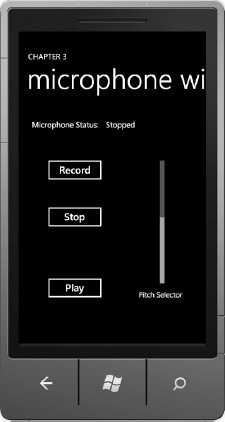
Figure 3–17. Microphone with Silverlight
Listing 3–10 shows the source code.
Listing 3–10. MainPage.xaml.cs Code File
using System;

using System.IO;

using System.Windows;

using Microsoft.Phone.Controls;

using Microsoft.Xna.Framework.Audio;


namespace MicrophoneWithSilverlight

{

  public partial class MainPage : PhoneApplicationPage

  {
Microphone microphone = Microphone.Default;
MemoryStream audioStream;
// Constructor
public MainPage()
{
InitializeComponent();
microphone.BufferReady +=
new EventHandler<EventArgs>(microphone_BufferReady);
SoundEffect.MasterVolume = 1.0f;
MicrophoneStatus.Text = microphone.State.ToString();
}
void microphone_BufferReady(object sender, EventArgs e)
{
byte[] audioBuffer = new byte[1024];
int bytesRead = 0;
while ((bytesRead = microphone.GetData(audioBuffer, 0, audioBuffer.Length)) > 0)
audioStream.Write(audioBuffer, 0, bytesRead);
MicrophoneStatus.Text = microphone.State.ToString();
}
private void recordButton_Click(object sender, RoutedEventArgs e)
{
if (microphone != null)
microphone.Stop();
audioStream = new MemoryStream();
microphone.Start();
MicrophoneStatus.Text = microphone.State.ToString();
}
private void stopRecordingButton_Click(object sender, RoutedEventArgs e)
{
if (microphone.State != MicrophoneState.Stopped)
microphone.Stop();
audioStream.Position = 0;
MicrophoneStatus.Text = microphone.State.ToString();
}
private void playButton_Click(object sender, RoutedEventArgs e)
{
SoundEffect recordedAudio =
new SoundEffect(audioStream.ToArray(), microphone.SampleRate,
AudioChannels.Mono); recordedAudio.Play(1f, (float)pitchSlider.Value, 0f);
}
}
}
With the Microphone class, developers can create fun applications that allow a user to record and playback recorded audio with pitch modifications.
Compass Sensor
The compass sensor has been a part of many Windows Phone devices since RTM in the original devices. However, no API was available to developers. The Windows Phone OS 7.1 and Tools (Mango) now provides an API to access compass data if a compass is available. You will need a physical device to test the compass. There isn't built-in compass simulation in the emulator. The next section provides more details on the compass sensor.
Compass Background
The compass sensor is actually a magnetometer sensor. It can be used to determine the angle by which the device is rotated relative to the Earth's magnetic North Pole. You can also use raw magnetometer readings to detect magnetic forces around the device. This is something to consider when testing and programming the compass sensor—it can be affected by magnetic objects such as magnets, speakers, and monitors, as well as large metal objects.
![]() Note The compass sensor is not required for all Windows Phone devices. It is important that you consider this when designing and implementing your application. Your application should always check to see whether the sensor is available and either provide an alternative input mechanism or fail gracefully if it is not.
Note The compass sensor is not required for all Windows Phone devices. It is important that you consider this when designing and implementing your application. Your application should always check to see whether the sensor is available and either provide an alternative input mechanism or fail gracefully if it is not.
You need to understand how the compass works in order to build applications for it. Figure 3-18 describes the compass functionality.

Figure 3–18. Compass functionalty
As you can see in Figure 3-18, the device is meant to be held flat in your hand with the top of the phone pointing in the direction of the current magnetic heading. As you rotate the phone about the “Z” axis with the phone flat in your hand, you change the current heading relative to magnetic north.
![]() Note Magnetic north can be different than true north found via GPS by several degrees.
Note Magnetic north can be different than true north found via GPS by several degrees.
The compass sensor can become inaccurate over time, especially if exposed to magnetic fields. There is a simple user action to recalibrate the compass that you can show the user how to do. I demonstrate how to work with the compass as well as the calibration process in the next section.
Coding with the Compass
In this sample we create a basic compass UI to demonstrate how to work with the compass. We create the UI in XAML and use Layout, Margin, and Padding to build out a simple compass UI that leverages the phone Accent color. You can just as easily create a nice image of compass rose and use that instead for the rotation.
I create a new project named CompassSensor and add it to the Chapter 3 part 2 solution in the Chapter 3 folder. The first thing I do is create a compass rose in XAML with the cardinal directions identified. I start with an Ellipse object named BoundingEllipse set to 200 Height and Width. I mark each cardinal direction using TextBlock control with alignment and Padding to position each TextBlock.
I group all of the controls into a Grid and name the Grid XamlCompass. I apply a RotationTransform to the Grid like this:
<Grid x:Name="XamlCompass" Margin="128,204,128,203" RenderTransformOrigin="0.5,0.5">

  <Grid.RenderTransform>

    <CompositeTransform x:Name="Angle" Rotation="0"/>

  </Grid.RenderTransform>
The idea is that you use the Rotation to always point the north cardinal direction toward magnetic north based on the orientation of the device and compass sensor or true north if using the TrueHeading reading. The last item I add is an orange line using a Rectangle to show the device heading, which is always the top direction of the phone if held in Portrait mode flat in your hand. Figure 3-19 shows testing the XamlMagCompass in Blend with the mouse by manipulating the Rotation value for the transform.
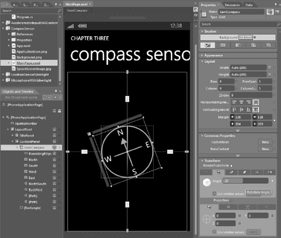
Figure 3–19. Testing rotation in Expression Blend
To use the compass sensor, add a reference to Microsoft.Devices.Sensors assembly. Next I declare a private compass property of type Compass as well as add a using Microsoft.Devices.Sensors statement at the top of MainPage.xaml.cs. I next create a new instance of the Compass object in the Initialize method and assign an event handler to the CurrentValueChanged event. In the compass_CurrentValueChanged event handler you get access to these items:
HeadingAccuracyMagneticHeadingMagnetometerReadingTimestampTrueHeading
You may be wondering what TrueHeading represents. TrueHeading represents the angle in degrees from Earth's geographic north whereas MagneticHeading represents the angle in degrees from Earth's magnetic north. The two North Poles generally do not align due to the irregular shape of Earth's magnetic core and can vary by your geographic location due to local magnetic interferences.
![]() Tip You will find
Tip You will find TrueHeading to be much more accurate than MagneticHeading.
I make a copy of the compass and name it TrueHeadingCompass and re-arrange the UI to show the other available values as shown in Figure 3-20.

Figure 3–20. Compass sensor test UI in action
In testing the compass application, the TrueHeading value does align pretty well with actual bearings, using my street as a reference and testing by pointing the phone parallel to the direction of my street. I obtained a rough bearing of my street heading using Bing Maps.
For most purposes, the TrueHeading value is what you and your users will want. MagneticHeading will generally vary wildly from geocoordinate references due to the Earth's magnetic north not aligning with true north. There are special situations for highly localized maps that actually use magnetic headings instead so it is always good to give your users an option of which value to use. Listing 3-11 shows the code that captures the compass reading and sets the values to the UI.
Listing 3–11. compass_CurrentValueChanged from MainPage.xaml.cs
void compass_CurrentValueChanged(object sender, SensorReadingEventArgs<CompassReading> e)

{

  if (compass.IsDataValid)

    ContentPanel.Dispatcher.BeginInvoke(() =>

      {

        XamlMagCompassAngle.Rotation = e.SensorReading.MagneticHeading* -1;

        XamlTrueCompassAngle.Rotation = e.SensorReading.TrueHeading*-1;

        MagHeadingValue.Text = String.Format("{0} degrees", e.SensorReading.MagneticHeading);

        TrueHeadingValue.Text = String.Format("{0} degrees", e.SensorReading.TrueHeading);
HeadingAccuracy.Text = "Heading Accuracy: " + e.SensorReading.HeadingAccuracy +" degrees";
MagnetometerReading.Text =
String.Format("Magnetometer: {0:0.00} microteslas",
e.SensorReading.MagnetometerReading.Length());
calibrationTextBlock.Text = e.SensorReading.HeadingAccuracy.ToString();
if (e.SensorReading.HeadingAccuracy > 10d)
calibrationTextBlock.Foreground = new SolidColorBrush(Colors.Red);
else
calibrationTextBlock.Foreground = new SolidColorBrush(Colors.Green);
});
}
The compass_CurrentValueChanged event handler fires on a background thread, so we need to call the Dispatcher.BeginInvoke(()=>{}) method to fire an anonymous delegate on the UI thread in order to safely access the UI controls and not encounter an exception.
In order to position the north axis with either true or magnetic north depending on which value is being used, you need to subtract the value returned from TrueHeading / MagneticHeading to determine which direction is north. In our case I use a CompositeTransform with a Rotation value, so I first multiply the returned value for TrueHeading / MagneticHeading by negative one and then set that to the Rotation value to push north “back” to the direction it points to, since heading is always fixed to the top of the phone in Portrait position.
The rest of the code is pretty straightforward, using String.Format to build out the values. Note that in this method it also updates the calibration UI as well even though it is not visible by default. The compass_Calibrate event is fired when the phone determines that the compass needs to be calibrated. You can force this by placing the phone near a large magnet—do this at your own risk! placed my phone near a pair of speakers and the compass_Calibrate event fires:
void compass_Calibrate(object sender, CalibrationEventArgs e)

{

  Dispatcher.BeginInvoke(() =>

    { calibrationStackPanel.Visibility = Visibility.Visible; });

}
This results in showing the UI listed in Figure 3-21.
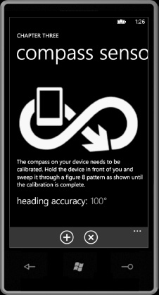
Figure 3–21. Compass calibration UI
If you move the phone in the figure eight pattern a few times you will see the heading accuracy value drop down to below 10 degrees and the heading accuracy number will turn green. Click the Back button to close the calibration dialog.
When you try the compass, it is somewhat jittery. The Compass class has a property named TimeBetweenUpdates. It defaults at 20ms, which is a fairly high sampling rate. One way to smooth it out is to sample less frequently. Experimenting with the value, I set it to 100 ms, which resulted in less jitter. Here is the initialization code:
public MainPage()

{

  InitializeComponent();

  if (Compass.IsSupported)

  {

    compass = new Compass();

    compass.TimeBetweenUpdates = TimeSpan.FromMilliseconds(100);

    compass.CurrentValueChanged += compass_CurrentValueChanged;

    compass.Calibrate += compass_Calibrate;

  }

}
Dead Reckoning Navigation
Dead Reckoning, or DR, navigation is the process of calculating your current position using a previously determined position, or “fix,” advancing position based on upon actual or estimated speed for a period of time and in a compass direction. DR navigation is one of the oldest forms of navigation but still a very useful form of navigation, especially when in locations where the location sensor and GPS are not available.
A compass can be used to perform basic DR navigation using your own walking speed, the compass for direction, and the clock. As you move in a direction, record the compass heading and amount of time on that course. When you make a turn, record the new bearing and restart the timer.
This type of navigation can be used to create mobile applications such as “find my car” in a large covered parking lot at the airport or navigation inside a large building or any other enclosed location where GPS is not available. In this section I create a basic DR navigation sample that we will enhance by adding support for the gyroscope and then rewrite it to take advantage of the motion sensor.
DRNavigation Sample
In this sample I demonstrate basic DR navigation using a compass and time. The assumption is that the user's walking speed is constant and the device is held flat in your hand when walking like you would hold a compass.
The application has minimal UI, just displaying the recorded “steps” in a databound ListBox to demonstrate data capture and turn detection. Since this must be tested on a device and not in the emulator, deploy this sample to your Windows Phone OS 7.1 device and give it a try following the instructions.
If you walk in a well-defined shape by say making 90 degree turns to form a square, you may still see quite a few steps when you might expect to see just four steps. However, if you look closely at the steps, you can group them together into four distinct sets representing the four 90 degree turns. The additional steps are a result of jitter as you are walking and holding a device, as well as compass accuracy.
You could employ a smoothing algorithm to further refine the steps down to just four steps by evaluating the compass and perhaps the accelerometer sensors, but that may not be completely necessary as we continue on with the chapter and cover the additional sensors available in Windows Phone 7.5.
DRNavigation with Compass Code
There is quite a bit of code in the DRNavigation sample so we cover the overall structure and then the key points that we will modify in subsequent sections as we add more sensors to the code. The UI consists of a ListBox control and the Application Bar. The Listbox is databound to an instance of the DeadReckoner class, which is where all the logic exists for navigation.
The DeadReckoner class consists of two DispatcherTimer instances, one that collects the sensor data and the other that processes the sensor data. The DispatcherTimer is a special timer class where the Tick event fires on the UI thread. The _fixTimer collects sensor data every 100 milliseconds, and the _processTimer processes SensorsFix records collected by the _fixTimer. Here is the SensorFix class declaration:
public class SensorsFix

{

  public int NavStepID;

  public AccelerometerReading AccelerometerReading;
public CompassReading CompassReading;
public GyroscopeReading GyroScopeReading;
public MotionReading MotionReading;
public DateTime FixTime;
public TimeSpan TimeSinceLastFix;
public bool Processed;
}
The class is a bit lazy in that it saves the “reading” value for each sensor. It could be made leaner to just collect the values of interest in a full application, but for now I picked simplicity.
The _processTimer evaluates the unprocessed SensorsFix objects to determine current motion (i.e., detecting whether the user is going straight or making a left or right turn). Time is tracked between readings and then added together to determine how long a particular navigation step lasts. Remember that direction (course) and time were the basic key components of dead reckoning navigation.
The unprocessed SensorsFix objects are combined into a single DRNavigationStep record with this class declaration:
public class DRNavigationStep

{

  //Link each reading to a Nav Step

  //This could allow additional post-processing

  //to make sure that the ultimate direction of turns

  //is correct by doing a full run through all steps

  //at the end of the captures

  static private int _nextStepID;

  static public int NextStepID

  {

    get

    {

      _nextStepID++;

      return _nextStepID;

    }

    set { _nextStepID = value; }

  }


  public int NavStepID { get; set; }

  public TimeSpan Time { get; set; }

  //if Direction is straight, maintain bearing

  //in a turn this is the new bearing to turn to

  public double Bearing { get; set; }

  public double Speed { get; set; }

  public DRDirection Direction { get; set; }

  public DRMovementState MovementState { get; set; }

}
The class has properties to track bearing or course, speed, and direction of type DRDirection. This is an enumeration type with values of TurningLeft, TurningRight, GoingStraight, and Unknown. DRMovementState indicates whether the user is Stopped, Moving, or Unknown.
The bulk of the logic, albeit not complex, is located in the _processTimer.Tick event handler named processTimer_Tick. Listing 3-12 has the code for this event handler.
Listing 3–12. The processTimer_Tick Event Handler in DeadReckoner.cs
void processTimer_Tick(object sender, EventArgs e)

{

  Debug.WriteLine("Eval Fixes Ticks" + DateTime.Now.Ticks.ToString());

  //Detect new DR fixes

  var unprocessedFixes = from reading in _fixReadings

                          where reading.Processed == false

                          select reading;


  if (unprocessedFixes.Count<SensorsFix>() == 0)

  {

    //No longer collecting data

    _processTimer.Stop();

  }

  else

  { //Process fixes

    //detect when going straight

    //detect when makng a turn

    //detect when coming out of a turn

    double currentBearing;

    double newBearing;

    double bearingDelta;


    DRNavigationStep currentNavStep;

    DRNavigationStep newStep;

    foreach (SensorsFix reading in unprocessedFixes)

    {

      //Always get latest in case a new step was added while processing

      currentNavStep = NavigationInstructions.Last();

      //bearing is changing

      newBearing = reading.CompassReading.TrueHeading;

      currentBearing = currentNavStep.Bearing;

      bearingDelta = currentBearing - newBearing;

      if (!(Math.Abs(bearingDelta) < BEARING_ACCURACY_LIMIT))

        //Adjust  direction based on current state

        switch (currentNavStep.Direction)

        {

          case DRDirection.TurningLeft:

            if (bearingDelta > 0)//still moving left

              currentNavStep.Bearing = reading.CompassReading.TrueHeading;

            else //stopped turning left

            {

              //done turning, add a new step to go straight

              newStep = new DRNavigationStep();

              newStep.NavStepID = DRNavigationStep.NextStepID;

              newStep.Bearing = reading.CompassReading.TrueHeading;

              newStep.Direction = DRDirection.GoingStraight;

              NavigationInstructions.Add(newStep);

            }

            currentNavStep.Time += reading.TimeSinceLastFix;

            break;

          case DRDirection.TurningRight:

            if (bearingDelta < 0)//still moving right
currentNavStep.Bearing = reading.CompassReading.TrueHeading;
else //stopped turning right
{
//done turning, add a new step to go straight
newStep = new DRNavigationStep();
newStep.NavStepID = DRNavigationStep.NextStepID;
newStep.Bearing = reading.CompassReading.TrueHeading;
newStep.Direction = DRDirection.GoingStraight;
NavigationInstructions.Add(newStep);
}
currentNavStep.Time += reading.TimeSinceLastFix;
break;
case DRDirection.GoingStraight:
if (OnCurrentCourse(currentNavStep, reading))
{
currentNavStep.Time += reading.TimeSinceLastFix;
}
else
{
newStep = new DRNavigationStep();
newStep.NavStepID = DRNavigationStep.NextStepID;
newStep.Bearing = reading.CompassReading.TrueHeading;
//update direction based on changes
if (bearingDelta > 0)
newStep.Direction = DRDirection.TurningLeft;
else
newStep.Direction = DRDirection.TurningRight;
NavigationInstructions.Add(newStep);
}
currentNavStep.Time += reading.TimeSinceLastFix;
break;
case DRDirection.Unknown:
break;
default:
break;
}
reading.Processed = true;
}
}
}
The first part of the event handler gathers up the unprocessed readings. If there are not any unprocessed readings, the code stops the timer. Otherwise the code enters a foreach loop to process the readings via a switch statement. The bearingDelta property represents the difference between the current reading and the current navigation step. To calculate it we have a constant named BEARING_ACCURACY_LIMIT.
If the delta between the current course and the new course obtained from the SensorsFix is greater than the BEARING_ACCURACY_LIMIT, it is detected as a turn. Otherwise, the time is added to the current navigation step as it is detected as continuing on course:
if (Math.Abs(bearingDelta) < BEARING_ACCURACY_LIMIT){
  currentNavStep.Time += reading.TimeSinceLastFix;

}

else

  //Adjust  direction based on current state

  switch (currentNavStep.Direction)

…
Check out the code to understand how it works. Notice that it implements two interfaces, IDisposable and INotifyPropertyChanged. The IDisposable interface is necessary because the sensors all implement IDisposable because they work with unmanaged resources (i.e., the sensors themselves). MainPage.xaml.cs calls Dispose on the DeadReckoner class when navigating away from the MainPage.
The INotifyPropertyChanged interface is necessary to support data binding, which is covered in Chapter 6. This completes the coverage of the compass sensor. Let's now move next to a discussion of the gyroscope sensor as well as what scenarios it enables.
Gyroscope Sensor
The gyroscope sensor is a new hardware sensor available on Windows Phone 7.5, though not mandatory. Windows Phone 7 devices do not have a gyroscope. This may cause concern with fragmentation of the Windows Phone ecosystem. Microsoft went to extra lengths to mitigate this issue by also providing the motion sensor, which abstracts out the gyroscope to provide sensor data with just accelerometer and compass, though in a slightly degraded mode. I cover the motion sensor in the next section. I'll first provide background on how a gyroscope works.
Gyroscope Background
The gyroscope sensor measures the rotational velocity of the device along its three primary axes. When the device is still, the readings from the gyroscope are zero for all axes. If you rotate the device around its center point as it faces you, like an airplane propeller, the rotational velocity on the Z axis will elevate above zero, growing larger as you rotate the device faster. Figure 3-22 shows the axis orientation for the gyroscope in relation to the phone.
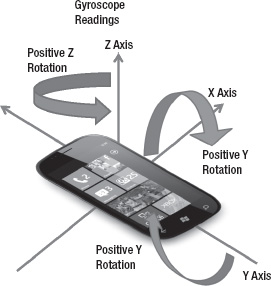
Figure 3–22. Gyrscope readings on 3-dimentional axis
The rotational velocity is measured in units of radians per second, where 2 * Pi radians are a full rotation. In Figure 3-22, if you hold the phone pointing away from you flat in your hand and then roll the phone from left to right, you will see positive Y rotation. If you flip the phone head to toe in your hand, you will see positive X rotation. Finally, if you rotate the phone flat in your hand counterclockwise, you will see positive Z rotation. If you are interested in determining the device's absolute orientation in space (yaw, pitch, and roll), you should use the combined Motion API, accessed using the Motion class, which I cover later in this chapter.
The gyroscope sensor is not required for all Windows Phone devices. Your application should always check to see whether the sensor is available and either provide an alternative input mechanism or fail gracefully if it is not. Also, be sure to mention that your application requires a gyroscope in the Marketplace description if that is the case.
Gyroscope Sample
The MSDN documentation has a useful walkthrough to help you understand how moving the phone in space affects the gyroscope readings. The walkthrough is available here:
http://msdn.microsoft.com/en-us/library/hh202943(v=VS.92).aspx
A modified version of the gyroscope code from MSDN is available in the GyroscopeSensor project as part of the Chapter 3 part 2 solution so that you can get a good feel for how the gyroscope values are affected by moving the device. Figure 3-23 shows the UI in the emulator.
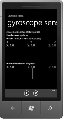
Figure 3–23. Gyroscope sensor project UI
The gyroscope is not supported in the emulator currently, so the three Line objects at the top all have a length of zero since there isn't a reading. Likewise, the three Lines on the bottom are on top of each other and not moving since there isn't a reading available. Still, Figure 3-23 gives you an idea of how it works.
The Line objects at the top indicate current readings in radians per second with positive length to the right and negative length to the left. The Line objects at the bottom rotate as the device rotates, depending on orientation, showing cumulative rotation. Try moving the device fast and slow around each access to get a feel for how the gyroscope is affected by moving the phone.
Gyroscope Readings
The gyroscope has a CurrentValueChanged event just like the other sensors on Windows Phone. In the event handler gyroscope_CurrentValueChanged, the e.SensorReading value includes the Timestamp value as for all sensor readings. The unique value to the Gyroscope SensorReadingEventArgs instance is the RotationRate property of type Vector3. A Vector3 consists of X, Y, and Z values of type float. The real-world units for the sensor readings are radians/second. 2*pi radians is equal to 360 degrees.
The gyroscope_CurrentValueChanged event handler also updates another Vector3 named cumulativeRotation. This is calculated by multiplying the current rotation rate Vector3, with units of radians per second, by the number of seconds since the last reading. This sets the cumulativeRotation Vector3 to have units of just radians:
cumulativeRotation += currentRotationRate * (float)(timeSinceLastUpdate.TotalSeconds);
The next subsection covers how the readings are used in the timer_Tick event for the Timer object to update the position of the Line objects that represent the current rotation values as well as the cumulative rotation values around the X, Y, and Z axes.
Visualizing the Gyroscope
The math behind it is pretty simple. For the upper portion of the UI of the sample that represents the current rotation, the X2 value for each Line object is changed depending on the current reading with a scaling factor of 100. The centerX value is calculated by taking the width of the Grid layout container and halving it. The centerX value applies the rotation value at the proper offset:
currentXLine.X2 = centerX + currentRotationRate.X * 100;

currentYLine.X2 = centerX + currentRotationRate.Y * 100;

currentZLine.X2 = centerX + currentRotationRate.Z * 100;
For the bottom portion of the UI, the Line objects need to change direction, which means that both the X2 and Y2 values must vary. Leaving, X1 and Y1 for each Line object in the same location while changing the X2 and Y2 values rotates the line around the center point, giving the visualization of the line changing as the phone rotates.
Taking this into account, the cumulative rotation values on the bottom half of the UI come from slightly more complicated calculations to determine the X2 and Y2 values for each Line object:
cumulativeXLine.X2 = centerX - centerY * Math.Sin(cumulativeRotation.X);

cumulativeXLine.Y2 = centerY - centerY * Math.Cos(cumulativeRotation.X);

cumulativeYLine.X2 = centerX - centerY * Math.Sin(cumulativeRotation.Y);

cumulativeYLine.Y2 = centerY - centerY * Math.Cos(cumulativeRotation.Y);

cumulativeZLine.X2 = centerX - centerY * Math.Sin(cumulativeRotation.Z);

cumulativeZLine.Y2 = centerY - centerY * Math.Cos(cumulativeRotation.Z);
With the use of the Sin and Cos functions in the Math namespace, the code calculates the X and Y end point for the line so that it presents the cumulative angle of turn relative to the start position.
Now that you understand how the gyroscope works, you can see that it enables a number of new types of applications. You can precisely detect the angle of turn using the gyroscope, even for small turns. This is in fact one of the ways that the Motion API leverages the gyroscope.
Another use for the raw gyroscope readings are to detect walking steps for a pedometer type of application. To see how it can be used, walk around while running the gyroscope sensor and you will see a pattern on how each step affects the gyroscope. These are just a few of the ways that a gyroscope can be used within an application. Now that you understand the gyroscope, let's jump straight to the motion sensor, because as you will see it has advantages over working with the raw sensors.
Motion “Sensor”
The motion sensor is not a physical sensor. It is an API that abstracts the compass, accelerometer, and gyroscope sensors with quite a bit of math by Microsoft Research to present a single integrated motion reading. The Motion API can account for the lack of a gyroscope in older devices and instead simulates the gyroscope using the accelerometer, compass, and complex mathematics. This allows developers to target both original and new Windows Phone codename ‘Mango' devices with a single application.
Motion API Background
The Motion API is useful for creating Windows Phone applications that use the device's orientation and movement in space as an input mechanism. The Motion API reads the raw accelerometer, compass, and gyroscope input and performs the complex math necessary to combine the data from these sensors to produce easy-to-use values for the device's altitude and motion.
In general, Microsoft recommends using the Motion API instead of direct sensor readings to provide maximum compatibility between devices. However, you always have the option to get access to the direct sensor data if needed. Cases where you may want direct access to hardware sensor readings are for custom motion algorithms where you need to interpret the data directly. Another example is if you need to detect something like a phone shake being used as a gesture for an application.
Motion API Benefits
The major benefit of the Motion API is that it attempts to leverage the strengths of each physical sensor while minimizing the weaknesses. The accelerometer can tell you the orientation of the phone by measuring gravitational forces to generate a 3D vector. The gyroscope cannot measure orientation, but it can tell you how much the orientation changes.
You saw this in the previous gyroscope sample. When you clicked start and turned 90 degrees, the Z component of the sensor reading also changed 90 degrees. The Motion API combines these two values to generate a single view of the device's orientation. It starts with the accelerometer as a baseline and then uses the gyroscope sensor to adjust these values. A weakness with the gyroscope is that it tends to drift over time. The accelerometer sensor can be used to “calibrate” the gyroscope readings.
Likewise, the gyroscope can be combined with the compass sensor to provide a more accurate sensor reading. A major benefit of the gyroscope is that it is unaffected by magnetic fields, which contributes to its having a smoother reading than the compass sensor.
The Motion API uses the compass to obtain true north and then uses the gyroscope's smoother movement to adjust the bearing. However, as mentioned previously, the gyroscope can drift, so the compass can be used to re-calibrate the reading. Taking advantage of multiple sensors allows the Motion API to provide smooth, accurate bearing change with the gyroscope while waiting for the slower compass sensor to catch up and settle on the current actual bearing. This is then used to re-calibrate the reading in case the gyroscope drifts over time.
You may conclude that technically the gyroscope is not required to obtain device orientation, which is correct. The accelerometer and compass are enough, which is why the Motion API can function on older devices without a gyroscope. However, the gyroscope is very fast and smooth, providing less jittery and more accurate readings, even for small changes.
Coding with the Motion API once again, the MSDN documentation provides a handy walkthrough to demonstrate how the motion sensor functions at this link:
http://msdn.microsoft.com/en-us/library/hh202984(v=VS.92).aspx
Grab the code at this link to see the code in action, but in reality you should have a pretty solid understanding at this point. The Motion API SensorReadingEventArgs returns the following values:
Attitude:Consists ofYaw,Pitch, andRollvaluesDeviceAcceleration:Returns the sameVector3as the acceleration sensor covered previouslyDeviceRotationRate:Returns the sameVector3as the gyroscope sensor covered previouslyGravity:Returns the direction ofGravity as a Vector3, essentially pointing to the center of the Earth (i.e., pointing to the ground, just like with the accelerometer sensor)Timestamp:Same as with previous sensors, it is the timestamp when the reading was calculated
The one value that the Motion API does not provide is current bearing, either magnetic or true. This is easily obtained by the compass, whereas the Motion API is focused on providing information on the device's altitude and movement in space.
You may be asking how yaw, pitch, and roll relate to the device's coordinate system. Figure 3-24 shows yaw, pitch, and roll with respect to the device's coordinate system.
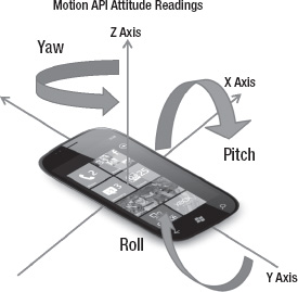
Figure 3–24. Motion API attitude values
With this background in hand, you could go and enhance the DRNavigation sample to have more precise readings regardless of the phones aspect. For example, the Yaw reading is the same whether the phone is in a horizontal/flat position or sitting vertical in your pocket. This simplifies creating a “Find My Car” application for Windows Phone in addition to the smoother turn detection available with the combined sensor Motion API.
I don't have a sample here with the motion sensor, as it is more interesting when used in combination with other sensors such as the new camera sensor to provide augmented reality scenarios as well as with the XNA Framework. I next discuss the camera sensor and how to take advantage of its capabilities. Later in Chapter 9 I cover how to use the motion sensor to create augmented reality scenarios that include 3D objects rendered by the XNA Framework. In Chapter 10 I cover how to build an augmented reality application that leverages both the Motion API and the camera sensor.
Camera Sensor
There is at least one camera on every Windows Phone device with a minimum of five megapixels in resolution. The camera on Windows Phone is accessible to developers. Developers could programmatically capture a photo but not video in Windows Phone 7. With Windows Phone 7.5 and the Windows Phone OS 7.1 developer tools, you can capture video, build your own custom camera UI, and build augmented reality scenarios using the camera sensor.
Camera Sensor Background
You can use the camera sensor to capture a photo. The simplest way to do that is with the CameraCaptureTask in the Microsoft.Phone.Tasks tasks and choosers API, which provides a simple method to capture a photo. I cover the camera task in Chapter 5. This is the basic functionality currently available in Windows Phone 7.
The base Camera class provides methods to determine CameraType, Orientation, PreviewResolution, and Resolution of the camera. The CameraType property determines the location of the camera on the device.
The PhotoCamera class allows you to develop applications that take high-resolution photographs, use the hardware shutter button, and access the flash mode or focus functionality. You can create a custom picture-taking application that provides additional features over the built-in camera functionality. The next section explores the PhotoCamera object in detail.
PhotoCamera
With Windows Phone 7.5 and the Windows Phone OS 7.1 developer tools, developers have an additional option available to capture a photo and programmatically modify the settings using the PhotoCamera class. The PhotoCamera class provides programmatic access to the camera settings like focus, resolution, and flash mode as well as events for camera focus, image capture, and image availability.
You use the CameraButtons class to detect when the hardware shutter button is half-pressed, pressed, and released. The GetPreviewBuffer method provides frames from the camera preview buffer in two formats, ARGB and YCbCr. ARGB is the format used to describe color in Silverlight UI. YCbCr enables efficient image processing but cannot be used by Silverlight. In order to manipulate a YCbCr frame you must convert it to ARGB.
Coding with the PhotoCamera
In this section I cover coding with the PhotoCamera object to demonstrate the flexibility available to you as a developer. I add a new project to the Chapter 3 part 2 solution named CameraSensor. I next add a folder named pages to put each test page starting with a landscape-oriented page named CustomCamera.xaml.
On the CustomCamera.xaml page, I create a custom camera UI that captures photos and adds them to the media library on the phone. To get access to the camera, add a using Microsoft.Devices statement to CustomCamera.xaml.cs. This brings in the PhotoCamera object, which is declared as photoCamera in CustomCamera.xaml.cs.
A variable of type MediaLibrary is declared as mediaLibrary in CustomCamera.xaml.cs to gain access to the MediaLibrary.SavePictureToCameraRoll API call. This allows your custom camera application to save photos to the camera roll and sync with the Zune client just like the built-in camera. The MediaLibrary is actually part of the Microsoft.Xna.Framework.Media namespace, so you also need to add a reference to Microsoft.Xna.Framework in CustomCamera.xaml.cs.
To display the camera preview in the UI, you use a VideoBrush object. In CustomCamera.xaml, I modify the LayoutRoot Grid object like this:
<Grid x:Name="LayoutRoot">

<Grid.Background>

  <VideoBrush x:Name="cameraViewFinder" />

</Grid.Background>

</Grid>
Windows Phone supports two types of cameras, CameraType.Primary and CameraType.FrontFacing. If a Windows Phone 7.5 device supports both types of camera, you can let the user choose which one he wants to use.
In the CustomCamera.xaml.cs code behind, I call VideoBrush.SetSource and pass in the PhotoCamera object to create the viewfinder:
void CustomCamera_Loaded(object sender, RoutedEventArgs e)

{

  _photoCamera = new PhotoCamera(CameraType.Primary);

  cameraViewFinder.SetSource(_photoCamera);

}
Figure 3-25 shows the viewfinder in the emulator.

Figure 3–25. Camera viewfinder
In Windows Phone OS 7.1 developer tools, the emulator supports camera emulation by moving a black square over a white background. This allows you to test photo apps in the emulator. Now let's build the UI to wrap the Camera API.
I add a Grid with a Rectangle object to the bottom of the UI. I then add a Flash button to the Grid with the idea that if you tap on the screen the Grid containing the UI to change the camera configuration animates into view.
The CustomCamera_Loaded event is expanded to wire up the camera events as well as the physical camera button on the phone to events that fire within the application:
void CustomCamera_Loaded(object sender, RoutedEventArgs e)

{

  //Can set to CameraType.FrontFacing if available

  _photoCamera = new PhotoCamera(CameraType.Primary);

  //wire up event handlers

  _photoCamera.AutoFocusCompleted += _photoCamera_AutoFocusCompleted;

  _photoCamera.CaptureCompleted += _photoCamera_CaptureCompleted;
_photoCamera.CaptureImageAvailable += _photoCamera_CaptureImageAvailable;
_photoCamera.CaptureStarted += _photoCamera_CaptureStarted;
_photoCamera.CaptureThumbnailAvailable += _photoCamera_CaptureThumbnailAvailable;
_photoCamera.Initialized += _photoCamera_Initialized;
//Wire up camera button
CameraButtons.ShutterKeyHalfPressed += CameraButtons_ShutterKeyHalfPressed;
CameraButtons.ShutterKeyPressed += CameraButtons_ShutterKeyPressed;
CameraButtons.ShutterKeyReleased += CameraButtons_ShutterKeyReleased;
//Set up view finder
cameraViewFinder.SetSource(_photoCamera);
LayoutRoot.Tap += LayoutRoot_Tap;
//Create MediaLibrary object
_mediaLibray = new MediaLibrary();
ThumbImages = new ObservableCollection<BitmapImage>();
ThumbImageLB.ItemsSource = ThumbImages;
}
The code sample for this section builds out a camera UI to demonstrate the features available to developers. Each picture you take with the sample will be added to the pictures hub as part of the camera roll section, just like with the built-in camera. The custom camera application will also show thumbnails of captured images in a ListBox on the right side of the UI just to demonstrate how to work with that section of the API. Figure 3-26 shows the full camera UI in the Windows Phone Emulator.
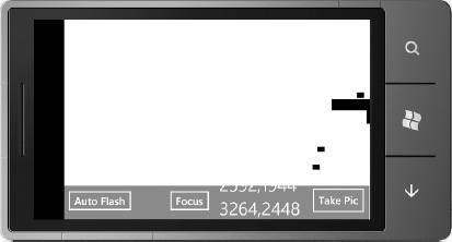
Figure 3–26. Full camera UI in the emulator
The black square floats around the screen to simulate a viewfinder. In Figure 3-26 the black square is behind photos taken using the Take Pic Button. The ListBox to the left of the Take Pic Button allows you to select the image capture resolutions. The other two buttons allow you to switch between the flash options like Off, On, and Auto. The second button allows you to focus the camera lens, if supported.
There is quite a bit of code in MainPage.xaml.cs, but most of the code simply wraps the PhotoCamera API. For example, this line of code captures an image:
To change to a different flash type, always call the IsFlashModeSupported method before modifying the FlashMode property. The code to save an image to the pictures hub is pretty simple:
void _photoCamera_CaptureImageAvailable(object sender, ContentReadyEventArgs e)

{

  _mediaLibray.SavePictureToCameraRoll("TestPhoto" +

             DateTime.Today.Date.ToString(), e.ImageStream);

  this.Dispatcher.BeginInvoke(() =>

  {

    cameraStatus.Text = "Image saved to camera roll...";

  });

}
The last few lines of code are sprinkled throughout the code. Dispatch.BeginInvoke marshals the anonymous delegate (()=>{…}) call back to the UI thread. Otherwise you will get a cross-thread access not authorized exception if you just tried to update the CameraStatus.Text outside of the anonymous delegate passed into the BeginInvoke method.
The other interesting code captures the thumbnail and data binds it in a ListBox control on the right side of the viewfinder UI. Here is the CaptureThumbnailAvailable event:
void _photoCamera_CaptureThumbnailAvailable(object sender, ContentReadyEventArgs e)

{

  this.Dispatcher.BeginInvoke(() =>

    {

      BitmapImage bitmap = new BitmapImage();

      bitmap.CreateOptions = BitmapCreateOptions.None;

      bitmap.SetSource(e.ImageStream);

      ThumbImages.Add(bitmap);

    });

}
ThumbImages is a simple ObservableCollection containing BitmapImage objects declared at the top of CustomCamera.xaml.cs:
ObservableCollection<BitmapImage> ThumbImages;
The data binding for this collection requires a simple “trick” to have the DataTemplate simply render the image. Here is the ListBox declaration from CustomCamera.xaml:
<ListBox x:Name="ThumbImageLB" Margin="0,6,8,2"

ItemTemplate="{StaticResource ThumbsDataTemplate}" HorizontalAlignment="Right" Width="133" />
Here is the data template:
<DataTemplate x:Key="ThumbsDataTemplate">

        <Grid Margin="0,0,0,30">

                <Image Height="100" Source="{Binding}"  Stretch="UniformToFill"/>

        </Grid>

</DataTemplate>
Notice in the DataTemplate that the Image.Source property simply has the value {Binding} without a property or field name. Usually in a ListBox, it data binds to an object with properties that are then configured in the DataTemplate. In this case, the object in the collection is what we want to render so the empty Binding call data binds the item directly in the DataTemplate.
Camera Examples
The MSDN documentation has two interesting camera samples that I recommend you check out if you are building a camera application. One covers how to convert the native camera YCbCr image format, which is highly efficient for the camera's use but not usable directly by image viewing programs. The sample covers converting the YCbCr format to ARGB so you can then display directly in the Silverlight UI:
http://msdn.microsoft.com/en-us/library/hh394035(v=VS.92).aspx
The other camera sample in the MSDN docs covers how to take an image and turn it into a black and white image:
http://msdn.microsoft.com/en-us/library/hh202982(v=VS.92).aspx
This concludes coverage of the camera sensor in this chapter. I cover how to build an augmented reality application using the camera sensor and Motion API in Chapter 10. The next couple of sections cover how to capture video using the camera and the new WebCam APIs available in Windows Phone OS 7.1 (Mango).
Video Capture
Another exciting capability in the Windows Phone OS 7.1 SDK is the ability to capture video within a custom application. There are two methods available to capture video in Windows Phone. One uses the camera CaptureSource object to get access to the camera video stream. The other method is via the Silverlight WebCam APIs ported from the desktop.
Camera CaptureSource Video Recording
The MSDN documentation covers how to use the CaptureSource object to capture video and pass it to a FileSink that records video output to Isolated Storage via the IsolatedStorageFIleStream object.
You can also capture an image using the CaptureSource.CaptureImageAsync method call. The image is returned in the CaptureImageCompleted event as a WritableBitmap. This capability is interesting because it provides a means to create bar code reader-type applications. Here is the link to the code sample:
http://go.microsoft.com/fwlink/?LinkId=226290WebCam APIs Video Recording
If you are more interested in capturing video in a format that can be played back by a user on his PC, the WebCam APIs are the way to go. The APIs allow you to capture both video and audio using the Silverlight 4 WebCam APIs but with enhancements for use on Windows Phone.
This link provides an overview of the Silverlight 4 class support available for video and audio capture:
http://msdn.microsoft.com/en-us/library/ff602282(VS.95).aspx
The WebCam APIs will generate an .MP4 file. This link provides a walkthrough of the process:
http://msdn.microsoft.com/en-us/library/hh394041(v=VS.92).aspx
PhotoCamera vs. WebCam APIs
It may seem odd to have two separate APIs interacting with the same piece of hardware. This section provides background on when you might want to use the PhotoCamera object vs. when you might want to use the WebCam APIs ported from Silverlight 4 with enhancements.
Use the PhotoCamera API when you need to obtain high quality photos, want support for the camera hardware button, and need to customize flash mode and camera focus.
The PhotoCamera class provides support for a “point and shoot” programming model as I described earlier and provides lower-level control over your polling rate. However, use the Silverlight 4 APIs now available on Windows Phone to encode the video.
![]() Note The Silverlight 4 APIs do not enable rate limiting, so you may be consuming more battery than necessary if you don't require 100% of frames. You can efficiently poll for frames by using
Note The Silverlight 4 APIs do not enable rate limiting, so you may be consuming more battery than necessary if you don't require 100% of frames. You can efficiently poll for frames by using PhotoCamera GetPreviewBuffer methods.
For best performance when using the VideoSink class in the Silverlight 4 APIs, specify the ReuseBuffer allocation mode. With ReuseBuffer, a new buffer is created for each sample capture. This can improve performance by reducing the amount of garbage collection that is required.
Conclusion
In the last chapter I covered Silverlight output. In this chapter I covered input for both Silverlight and XNA Game Studio, covering text input and the value of InputScope. I next moved on to touch and multi-touch, covering the range of APIs available to developers, and I covered accelerometer input for both Silverlight and the XNA Framework. The next sections focused on location and fun with the microphone.
With the introduction of new sensor APIs available in the Windows Phone OS 7.1 developer tools, I also covered the new Compass, Gyroscope, and Motion APIs, which greatly enhance the types of applications you can build for Windows Phone.
The new Camera Sensor API provides the ability to build rich photo and video capture applications. The Camera API also enables the ability to create bar code scanner-type applications for Windows Phone.
With the overview in Chapter 1, rendering in Chapter 2, and input in Chapter 3 out of the way, I next dive deep into the application programming model in Chapter 4.