
Chapter 8. Acceleration
Some games are controlled by tilting a phone in the air, using the accelerometer. The popular Wii game console uses an accelerometer for its controllers. In this chapter, you will hack a Wii controller to use its sensors. We used a phone accelerometer for control in the Football Robot from Make: Arduino Bots and Gadgets.
Hard disks found in laptops and desktops can now take a lot of punishment. Many are rated to take a shock of 150 g (when off), an acceleration that would immediately kill any human. To brace for impact, some drives will turn themselves off: when the hard disk accelerometer detects it’s in free fall, it automatically moves the actuator arm away from the sensitive plates.
Have you ever tried to ride a self-balancing device, like a Segway or a Solowheel? After perhaps a shaky start, it almost feels like a miracle that the device stays upright.
When a self-balancing device detects that it’s about to fall over forward, it quickly moves its wheels forward, turning itself upright again. Self-balancers measure angular velocity with a gyroscope. (An accelerometer would gather too many cumulative errors to work in a self-balancing device.)
Acceleration vs. Angular Velocity
Acceleration is the rate at which an object’s velocity changes (when it’s slowing down or speeding up). Angular velocity measures the rotational speed of an object, as well as the axis that it’s rotating around. Depending on your project, you might need acceleration, angular velocity, or even both.
Acceleration is measured in g, as a multiple of the acceleration caused by Earth’s gravity. Another commonly used unit of acceleration is meters per second squared (m/s2). Free-fall acceleration (1 g) is 9.81 m/s2.
Why are the seconds squared in acceleration? Acceleration is change in speed. If you’re using meters per second (m/s) as a unit of speed, then the unit of acceleration (change of speed) is meters per second per second, or m/s2.
Gyroscopes measure angular velocity, or how fast the sensor is rotating around an axis. For example, a gyroscope might report it’s rotating at 10 degrees per second. They are used in self-balancers and airplane gyrocompasses.
Experiment: Accelerate with MX2125
MX2125 is a simple two-axis acceleration sensor (see Figure 8-1). It reports acceleration as a pulse length, making the interface and code simple.
The real, physical world is three dimensional. Objects can go up and down (y), left and right (x), and back and forth (z). A two-axis sensor only measures two of these axes.
The MX2125 only measures up to 3 g per axis. But some sensors can measure extreme acceleration. For example, the maximum measured acceleration of the ADXL377 (200 g), is much more than would kill any human. Thus, it’s more than is experienced in a shuttle launch or high-g maneuvers in fighter jets. It could measure an object accelerating faster than a bullet fired from a pistol. When we made an early prototype for an Aalto-1 satellite sun sensor, even the satellite spec did not require acceleration this tough.
It’s unlikely that you would need to measure such an extreme acceleration, and it would probably not be possible with a breadboard setup (because the acceleration needed to test would shake your project apart!). The cost is quite minimal, though. However, the wider the area of measured acceleration (from -250 g to +250 g), the less precise the device is.

Decoding MX2125 Pulse Length
Usually, an accelerometer’s conversion formulas are found on data sheets. In this case, it required some more searching.
MX2125 works by heating a bubble of gas inside the device, and then measuring how the air bubble moves.
When power is on, the MX2125 reports the acceleration on each axis, 100 pulses a second. Consecutive HIGH and LOW signals form a 100 Hz square wave. The more acceleration there is, the more time the wave spends in the HIGH portion, and the less time in the LOW portion. You can read these pulses to determine acceleration.
One full wave contains one HIGH and one LOW. The time taken by one wave (HIGH+LOW) is called period (T). Let’s call the time of HIGH part tHIGH (time of HIGH).
The duty cycle tells you how much of the wave is HIGH. The duty cycle is a percentage, for example 50% (0.50) or 80% (0.80).
dutyCycle = tHIGH / T
According to the data sheet and other documents, the period T is set to 10 ms by default:
dutyCycle = tHIGH / 10 ms
Here’s the acceleration formula from the data sheet:
A = (tHIGH/T-0.50)/20%
Or, replacing tHIGH/T with dutyCycle and 20% with .2:
A = (dutyCycle-0.50)/.2
Now it can be written as follows (because x/.2 is 5*x):
A = 5*(dutyCycle-0.50)
or:
A = 5*(tHIGH/T-0.50)
When there is no acceleration (0 g), the duty cycle is 50%:
0   = 5*(dutyCycle-0.50)
0/5 = dutyCycle-0.50
0   = dutyCycle-0.50
.50 = dutyCycle
At the time we originally checked, the Parallax and Memsic documentation conflicted on the multiplier: the Memsic documentation used 1/20% (5), and Parallax used 1/12.5% (8). In our experiments, we found 1/12.5% (8) to give proper readings with the breakout board from Parallax. And in fact, when we later examined the MXD2125 data sheet from Memsic that was hosted on Parallax’s site, both agreed on 1/12.5%. This is why you need to be careful with data sheets you find online: always verify the values with experimentation. So we will use 8 as the multiplier:
A = 8*(tHIGH/T-0.50)
Because Arduino pulseIn() returns the pulse length in microseconds (1 µs = 0.001 ms = 1e-6 s), the formula could be modified to use microseconds:
A = 8 * ( tHIGH/(10*1000) - 0.5)
The unit of A is then g, which equals 9.81 m/s2.
For example, if tHIGH is 5,000 µs (5 ms), the duty cycle is
dutyCycle = 5 ms / 10 ms = 0.50 = 50%
Which equals 0 g:
A = 8*(0.50-0.5) = 8*0 = 0 // g
To show another example, consider tHIGH of 6250 µs (6.25 ms)
A = 8*(6250/10000-0.5) = 8*(0.625-0.5) = 8*0.125 = 1 // g
Thus, a 6.25 ms pulse means 1 g acceleration.
Accelerometer Code and Connection for Arduino
Figure 8-2 shows the circuit diagram for Arduino. Wire it up as shown, and load the code from Example 8-1.
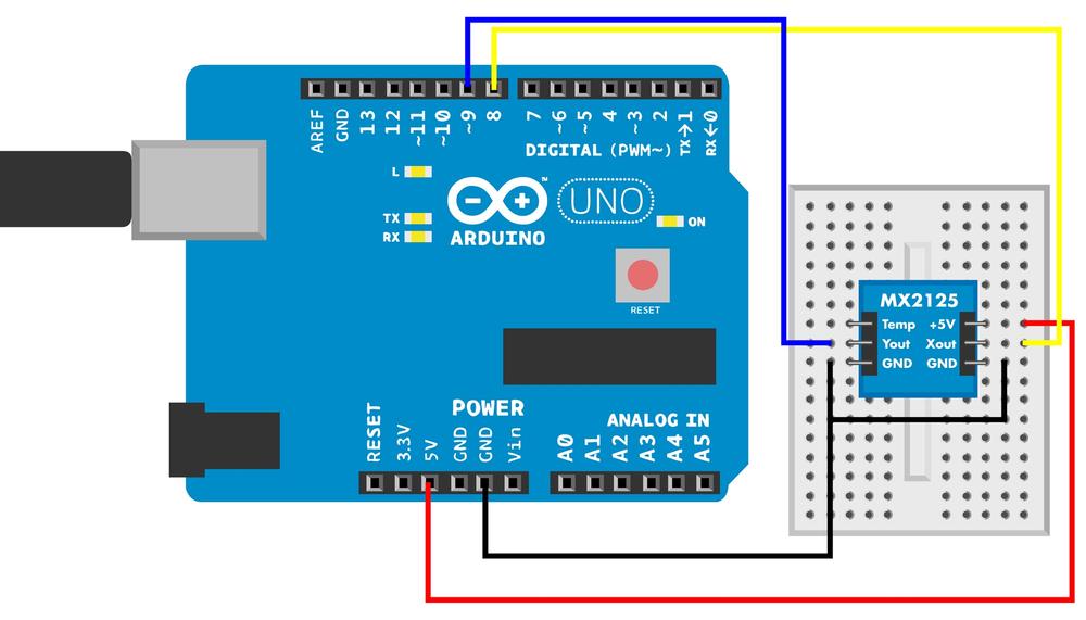
// mx2125.ino - measure acceleration on two axes using MX2125 and print to serial// (c) BotBook.com - Karvinen, Karvinen, ValtokariconstintxPin=8;constintyPin=9;voidsetup(){Serial.begin(115200);pinMode(xPin,INPUT);pinMode(yPin,INPUT);}voidloop(){intx=pulseIn(xPin,HIGH);//inty=pulseIn(yPin,HIGH);intx_mg=((x/10)-500)*8;//inty_mg=((y/10)-500)*8;Serial.("Axels x:");Serial.(x_mg);Serial.("y:");Serial.println(y_mg);delay(10);}

The length of the pulse tells you the acceleration.
pulseIn()returns the pulse length in microseconds (µs). 1 µs = 0.001 ms = 0.000001 s = 1e-6 s.
Convert output to millig, one-thousandth of the gravity constant g.
Accelerometer Code and Connection for Raspberry Pi
Figure 8-3 shows the wiring diagram for the Raspberry Pi. Hook everything up as shown, and then run the code shown in Example 8-2.
# mx2125.py - print acceleration axel values.# (c) BotBook.com - Karvinen, Karvinen, Valtokariimporttimeimportbotbook_gpioasgpioxPin=24yPin=23defreadAxel(pin):gpio.mode(pin,"in")gpio.interruptMode(pin,"both")returngpio.pulseInHigh(pin)#defmain():x_g=0y_g=0whileTrue:x=readAxel(xPin)*1000y=readAxel(yPin)*1000if(x<10):#x_g=((x/10)-0.5)*8#if(y<10):y_g=((y/10)-0.5)*8("Axels x:%fg, y:%fg"%(x_g,y_g))#time.sleep(0.5)if__name__=="__main__":main()
-
Measure the length of pulse, the time when the pin is HIGH.
-
Ignore readings that are wildly out of range.

Calculate the acceleration along x axis in g. One g is the acceleration caused by the gravity of earth, 9.81 meters per second squared.

Experiment: Accelerometer and Gyro Together
When an accelerometer is not moving, it detects gravity and can tell where down is. A gyroscope can tell the orientation reliably, even if you spin it around and around. A gyroscope ignores gravity, though.
Could we combine an accelerometer and gyroscope to get both benefits? Yes.
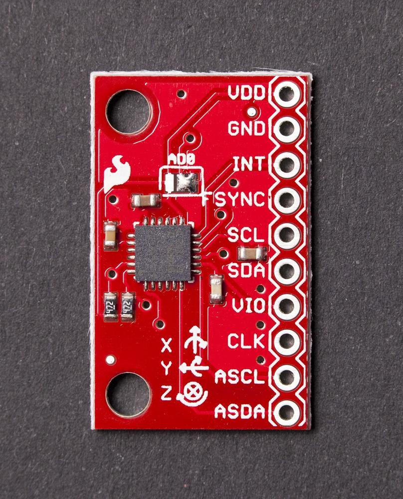
An IMU (inertial measurement unit) combines multiple sensors and (optionally) some logic to get more precise and reliable motion information. In this experiment, you’ll work hands-on with the basic features of the MPU 6050.
In general, IMUs are more expensive and more precise than plain accelerometers and gyros. They also use more advanced protocols to communicate, such as I2C, instead of a simple pulse width signaling protocol.
The MPU 6050 (Figure 8-4) has an accelerometer, gyro, and microcontroller on the same chip. Even though space isn’t a premium when you’re in the breadboard prototyping stage, it’s nice to know that all this functionality fits in a tiny surface-mounted component, just in case you ever run short of circuit real estate. For example, an early prototype of a sun sensor we designed barely fit into a box of about 10 × 10 × 10 cm. The final part had to fit into a very flat 5 mm × 5 mm area on the satellite surface.
The MPU 6050 uses the I2C protocol. Thanks to the python-smbus library, Raspberry Pi code is much simpler and easier than the equivalent Arduino code. In general, Raspberry Pi handles complicated protocols in less code than Arduino.
MPU 6050 Code and Connection for Arduino
Figure 8-5 shows the wiring diagram for Arduino. Hook everything up, and then run the code in Example 8-3.

Difficult code! The code for MPU 6050 contains more difficult programming concepts than most other code examples in this book. If you find endianness, bit shifting, and structs difficult, you can simply use the code and play with the values. You don’t need to deeply understand the code to use it.
If you want to understand the code, see the explanations after the code, such as Hexadecimal, Binary, and Other Numbering Systems and Bitwise Operations.
// mpu_6050.ino - print acceleration (m/s**2) and angular velocity (gyro, deg/s)// (c) BotBook.com - Karvinen, Karvinen, Valtokari#include <Wire.h>//constchari2c_address=0x68;//constunsignedcharsleep_mgmt=0x6B;//constunsignedcharaccel_x_out=0x3B;structdata_pdu//{int16_tx_accel;//int16_ty_accel;int16_tz_accel;int16_ttemperature;//int16_tx_gyro;//int16_ty_gyro;int16_tz_gyro;};voidsetup(){Serial.begin(115200);Wire.begin();//write_i2c(sleep_mgmt,0x00);//}int16_tswap_int16_t(int16_tvalue)//{int16_tleft=value<<8;//int16_tright=value>>8;//right=right&0xFF;//returnleft|right;//}voidloop(){data_pdupdu;//read_i2c(accel_x_out,(uint8_t*)&pdu,sizeof(data_pdu));//pdu.x_accel=swap_int16_t(pdu.x_accel);//pdu.y_accel=swap_int16_t(pdu.y_accel);pdu.z_accel=swap_int16_t(pdu.z_accel);pdu.temperature=swap_int16_t(pdu.temperature);//pdu.x_gyro=swap_int16_t(pdu.x_gyro);pdu.y_gyro=swap_int16_t(pdu.y_gyro);pdu.z_gyro=swap_int16_t(pdu.z_gyro);floatacc_x=pdu.x_accel/16384.0f;//floatacc_y=pdu.y_accel/16384.0f;floatacc_z=pdu.z_accel/16384.0f;Serial.("Accelerometer: x,y,z (");Serial.(acc_x,3);Serial.("g,");//Serial.(acc_y,3);Serial.("g,");Serial.(acc_z,3);Serial.println("g)");intzero_point=-512-(340*35);//doubletemperature=(pdu.temperature-zero_point)/340.0;//Serial.("Temperature (C):");Serial.println(temperature,2);Serial.("Gyro: x,y,z (");Serial.(pdu.x_gyro/131.0f);Serial.("deg/s,");//Serial.(pdu.y_gyro/131.0f);Serial.("deg/s,");Serial.(pdu.z_gyro/131.0f);Serial.println("deg/s)");delay(1000);}voidread_i2c(unsignedcharreg,uint8_t*buffer,intsize)//{Wire.beginTransmission(i2c_address);//Wire.write(reg);//Wire.endTransmission(false);//Wire.requestFrom(i2c_address,size,true);//inti=0;//while(Wire.available()&&i<size){//buffer[i]=Wire.read();//i++;}if(i!=size){//Serial.println("Error reading from i2c");}}voidwrite_i2c(unsignedcharreg,constuint8_tdata)//{Wire.beginTransmission(i2c_address);//Wire.write(reg);Wire.write(data);Wire.endTransmission(true);}
-
Wire.h is the Arduino library for the I2C protocol. Wire.h comes with the Arduino IDE, so you can just include the library in your code. You don’t need to separately install the library or copy any library files manually.
-
The I2C address of the MPU 6050 sensor. One three-wire bus can have many slaves. Each slave is recognized by its address. Typically, an I2C bus can have 128 (27) slaves. The I2C wires can be only a couple of meters long, so that also puts a practical limit to wire length. The number is represented in hexadecimal, see Hexadecimal, Binary, and Other Numbering Systems for an explanation of this notation.
-
The registers for commands are from MPU 6050 documentation. If you need a complete list of commands, search the Web for “MPU 6050 data sheet” and “MPU 6050 register map.” The numbers are in hex but could be expressed in decimal if you prefer.

The struct for decoding the answer from the sensor. A struct combines multiple values together. The C struct is only for data, and a struct can’t contain any functions. This makes structs different from objects and classes you may be familiar with from other languages.
struct data_pdudeclares a new data type, which you’ll later use for declaring variables of typedata_pdu. This struct has variables that are exactly the same size as the data fields in the protocol used by the sensor. Later, you will read bytes from the sensor directly into the struct. Then you’ll go through the variables embedded in the struct to get at the values. Yes, it’s a neat trick!
A variable for storing acceleration across the horizontal x-axis. The type
int16_tis a specifically sized integer defined by avr-libc (the C library used by the Arduino compiler). It’s a signed (negative or positive) 16-bit (two-byte) integer. Because the struct is used for decoding raw data from the sensor, the exact sized data types are required.
The sensor also reports temperature. Even if you don’t need it, you must have a variable for it so that the
data_pdustruct ends up being the right size.
Angular velocity around x-axis (roll), read by the gyroscope portion of the MPU 6050.

Initialize I2C communication using the Wire.h library.

Wake up the sensor by writing the command
0to the sleep management register0x6B. The MPU 6050 starts out in sleep mode, so this is a required step.
Swap the two bytes in parameter value. MPU 6050 is big endian. Arduino is little endian like most processors. The endianness must be converted between the platforms. See Endianness—Typically on the Small Side for more details.

This new two-byte (16 bit) variable
leftends up being the rightmost byte of the parametervalue. After a one-byte (8 bit) left shift (<<), the leftmost byte ofvalueis dropped, as it doesn’t fit the two bytes ofleft. The right byte ofleftis filled with zeroes in the bit shift.
This new two-byte (16 bit) variable
rightis now the leftmost byte ofvalue. The leftmost byte ofrightis zeroes.
Zero out the leftmost byte of
right, just to make sure it’s empty. See also Bit Masking with Bitwise AND &
Combine the left and right bytes. The variable
leftis actually two bytes (16 bits), with the rightmost byte (8 bits) full of zeroes. See also Bitwise OR |
Create a new variable
pduof typedata_pdu. This is the struct type you created earlier.
Fill the
pdustruct with data from the sensor. The first parameter is the register to read(accel_x_out, 0x3B). The second parameter is a reference to thepdustruct. It is passed as a reference, so that the function can modify the struct itself instead of returning a value. The last parameter is how many bytes to read. Conveniently, you can use the size of the struct to specify the number of bytes to read.
Convert the number from the sensor’s big endian format to little endian used in Arduino.

You can refer to the variables in the struct with
structname.var, such aspdu.temperature.
The raw acceleration value is converted to the real-life unit g. The standard gravity
gis9.81 m/s2. The conversion factor is from the data sheet. To get a floating point (decimal) result, the divider must be floating point.
Print the acceleration to the serial monitor. The unit is g, the acceleration from gravity. 1 g = 9.81 m/s2.

Calculate the zero point for converting raw measurement to temperature in Celsius, using information from the data sheet. The temperature is from -40 C to +85 C. A raw value of -512 indicates 35 C. From that point, every 1 C change is represented by a raw value change of 340. Thus, to find the 0 C point raw value, you take -512 and subtract the product 340 * 35 (deducting 35 C worth of raw values at 340 per C). The calculation is
-512 - (340 * 35), which is -12412. But instead of writing the calculated value -12412, you should write the calculation from the datasheet so that the code is more clear.
Convert raw measurement to temperature in Celsius, using the formula from the data sheet.

Print angular velocity as measured by gyroscope. The raw to degree/s conversion factor 1/131.0 is from the data sheet. To get a floating point (decimal) result, the divider must be floating point, too.

A function to read
sizenumber of bytes from registerpoint. The result is written over the struct, which is represented by the*bufferpointer. Because of the pointer, the actual value of the struct is modified, instead of returning a value.
Send the I2C command to the device (the MPU 6050 sensor in the address 0x69).

Specify the register address to read. In this program,
read_i2c()is only used to read fromaccel_x_out(0x3B).
Keep the connection open, so that you can read data on the next lines.

Request
sizebytes of data from the sensor. Earlier, you stated you want to start from registeraccel_x_out(0x3B). Thetrueparameter (the third argument, which is namedstopin the Arduino documentation) means that the connection is closed after the read ends, which releases the I2C bus for future use.
Declare a new variable for the upcoming
whileloop. The loop variableiholds the count of how many bytes have been read. This countiequals the number of iterations the loop has run.
Enter the loop only if there are bytes available for reading and you have not yet read all the bytes requested. In the way
read_i2c()is called in this program, the variablesizewill always be the length ofdata_pdustruct.
Read a byte (8 bits) and store it into the buffer. Considering how
read_i2c()is called in this program, we can walk through the first iterations. The pointer*bufferpoints to the first byte ofpdu, which is of struct typedata_pdu. On the first iteration,iis 0, sobuffer[i]points to the first byte ofpdu. Becausepduwas passed to the function with a pointer, the contents of the actualpdu(the variable in the main program) are overwritten. No return is needed, so the type ofread_i2c()is void. On the second iteration,buffer[1]points to the second byte ofpdu. This continues for the whole buffer (pdu). Wheni == size, thewhileloop is not re-entered, and execution continues with the code that comes after thewhileloop.
If not enough bytes were available, the loop variable
iis less thansize. Asiwas declared outside the loop, it is available to you after the loop.
Write one byte
datato registerregon the sensor.
The address of the sensor comes from the global variable
i2c_address.
MPU 6050 Code and Connection for Raspberry Pi
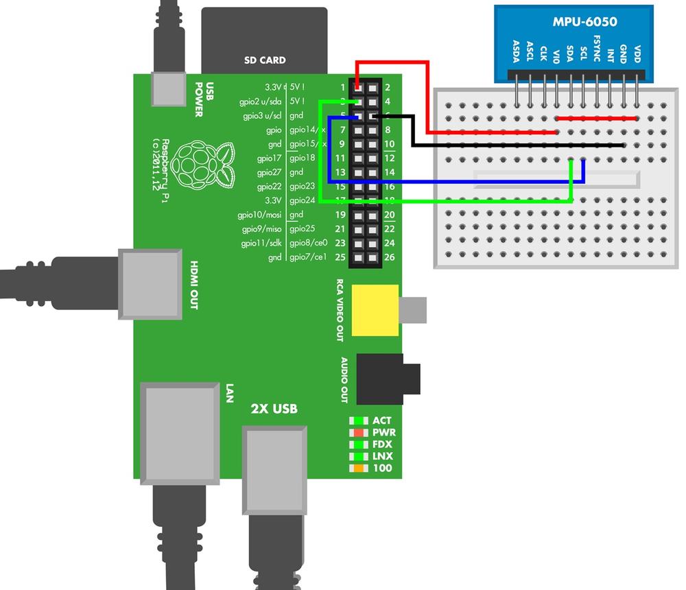
Figure 8-6 shows the wiring diagram for Raspberry Pi. Hook it up as shown, and then run the code from Example 8-4.
# mpu_6050.py - print acceleration (m/s**2) and angular velocity (gyro, deg/s)# (c) BotBook.com - Karvinen, Karvinen, Valtokariimporttimeimportsmbus# sudo apt-get -y install python-smbus #importstructi2c_address=0x68#sleep_mgmt=0x6B#accel_x_out=0x3B#bus=None#acc_x=0acc_y=0acc_z=0temp=0gyro_x=0gyro_y=0gyro_z=0definitmpu():globalbus#bus=smbus.SMBus(1)#bus.write_byte_data(i2c_address,sleep_mgmt,0x00)#defget_data():globalacc_x,acc_y,acc_z,temp,gyro_x,gyro_y,gyro_zbus.write_byte(i2c_address,accel_x_out)#rawData=""foriinrange(14):#rawData+=chr(bus.read_byte_data(i2c_address,accel_x_out+i))#data=struct.unpack('>hhhhhhh',rawData)#acc_x=data[0]/16384.0#acc_y=data[1]/16384.0acc_z=data[2]/16384.0zero_point=-512-(340*35)#temp=(data[3]-zero_point)/340.0#gyro_x=data[4]/131.0#gyro_y=data[5]/131.0gyro_z=data[6]/131.0defmain():initmpu()whileTrue:#get_data()#("DATA:")("Acc (%.3f,%.3f,%.3f) g,"%(acc_x,acc_y,acc_z))#("temp%.1fC,"%temp)("gyro (%.3f,%.3f,%.3f) deg/s"%(gyro_x,gyro_y,gyro_z))time.sleep(0.5)# s #if__name__=="__main__":main()
-
SMBus implements a subset of the I2C industry standard protocol. The SMBus library makes the Raspberry Pi program much shorter than the Arduino equivalent. The
python-smbuspackage must be installed on Raspberry Pi (see SMBus and I2C Without Root for instructions).-
The I2C address of MPU 6050 sensor, found on the data sheet. The number is represented in hexadecimal (see Hexadecimal, Binary, and Other Numbering Systems).
-
The register address for commands. You can find the register map by searching the Web for “MPU 6050 register map”.
-
The X acceleration register address is the starting address for the values you’re interested in: acceleration, temperature, and angular velocity.
-
Make
busa global variable visible to all functions.-
To modify the value of a global variable in a function, you must indicate that it’s global in the beginning of the function.
-
Initialize the SMBus (I2C). Store the new object of the SMBus class into the global
busvariable.-
MPU 6050 starts in sleep mode. Wake it up before doing anything with it. The commands to the sensor are given over I2C (SMBus) with the device address, the register, and the value to write to the register.
-
Request data, starting from the X acceleration address.
-
Repeat 14 times, with values of
i, from 0 to 13.-
Read the current byte, convert it to ASCII, and add it to
rawDatastring.-
Convert the
rawDatastring to a Python tuple. The format string characters indicate little endian<, short signed 2 byte (16 bit) integerh.-
Convert raw acceleration to real-life g units. The standard gravity g is equal to 9.81 m/s2.
-
Calculate the temperature zero point. The Pi does it very quickly, and writing the whole formula here makes code easier to read and typos less likely.
-
Convert raw temperature to Celsius. To get a floating point result, the divider must also be floating point. Conversion formulas are from the data sheet (Google “MPU 6050 data sheet”).
-
Convert raw angular velocity to real-life units (degrees per second).
-
The program runs until you press Control-C.
-
get_data()updates global variables, so it doesn’t need to return values from the function.-
Print acceleration using the format string. The replacement
%.3findicates a floating point value with three decimal places.-
To let the user read the printed values and avoid taking 100% of CPU time, we add a small delay here.
Find out what walking, running, or skipping does to readings. How about twitching or squirming?
SMBus and I2C Without Root
The Raspberry Pi code uses the Python smbus library for I2C. Luckily, installing software in Linux is a breeze. You can install any software to Raspbian just like you would install it in Debian, Ubuntu, or Mint. Double-click the LXTerminal icon on the left side of your Raspbian desktop. Then:
$ sudo apt-get update
$ sudo apt-get install python-smbus
To enable I2C support, you’ll need to enable the i2c modules. First, make sure they are not disabled. Edit the /etc/modprobe.d/raspi-blacklist.conf with the command sudoedit /etc/modprobe.d/raspi-blacklist.conf and delete this line:
blacklist i2c-bcm2708
Save the file: press Control-X, type y, and then press Enter or Return.
Next, edit the /etc/modules with the command sudoedit /etc/modules and add these two lines:
i2c-bcm2708
i2c-dev
Save the file: press Control-X, type y, and then press Enter or Return.
To use I2C without needing to be root, create the udev rule file 99-i2c.rules (shown in Example 8-5) and put it in place. (To avoid typing and inevitable typos, you can download a copy of 99-i2c.rules file from http://botbook.com.)
$ sudo cp 99-i2c.rules /etc/udev/rules.d/99-i2c.rules
# /etc/udev/rules.d/99-i2c.rules - I2C without root on Raspberry Pi# Copyright 2013 http://BotBook.comSUBSYSTEM=="i2c-dev",MODE="0666"
Reboot your Raspberry Pi, open LXTerminal, and confirm that you can see the I2C devices and that the ownership is correct:
$ ls -l /dev/i2c*The listing should show two files, and they should list permissions of crw-rw-rwT. If not, go over the preceding steps again.
Hexadecimal, Binary, and Other Numbering Systems
The same number can be represented multiple ways. For example, the decimal number 65 is 0x41 in hexadecimal and 0b1000001 in binary. You are probably most familiar with the normal decimal system, where 5+5 is 10.
The different representations are marked with a prefix before the number. Normal decimal numbers don’t have a prefix. Hexadecimal numbers start with 0x, binary numbers start with 0b, and octal numbers start with 0.
The different numbering systems are compared in Table 8-2.
| Prefix | Representation system | Base | Use | Example | Calculation |
Decimal | 10 | The normal system | 10 | 0*100 + 1*101 | |
0x | Hexadecimal | 16 | C and C++ code, datasheets | 0xA | 10*160 |
0b | Binary | 2 | Low-level protocols, bit-banging | 0b1010 | 0*20 + 1*21 + 0*22 + 1*23 |
0 | Octal | 8 | Chmod permissions in Linux | 012 | 2*80 + 1*81 |
Consider the number 42. It is the exact same number in any representation system, so
42 = 0x2a = 0b101010 = 052
Only the base number changes. With the familiar, normal decimal system, the base is 10. Starting from the right, you first count ones and then tens.
2*1 + 4*10 = 42
If there is a big number, such as 1917, the ten is obvious. After ones, it’s tens (10), hundreds (10*10) and thousands (10*10*10). You can easily write these numbers as powers:
10*10 = 102
10*10*10 = 103
What about ones? Any number to zeroth power is 1, so it’s:
100 = 1
Thus, the number 42 becomes:
42 = 4*101 + 2*100
The hex representation of 42 is 0x2A. In hex, numbers bigger than 9 are shown with letters: A=10, B=11 … F=15. Starting from the right, note that A is 10 and count:
0x2A = 10*1 + 2*16 = 10 + 32 = 42
To play with powers, this can be written
10*160 + 2*161 = 0x2A
Try some other numbers. To check your calculations, use the Python console (see The Python Console or Table 8-3). Can you apply your skills to convert to binary numbers, too?
You can practice working with numbers in the Python console. The number representation (1 == 0x1 == 0b1) is the same in Python, C, and C++. You can run any Python commands in the console:
>>> print("Botbook.com")
Botbook.com
>>> 2+2
4
Any numbers you enter are converted to decimal system for display:
>>> 0x42
66
>>> 66
66
>>> 0b1000010
66
There are functions to convert any number to binary, hexadecimal, octal, and ASCII characters:
>>> bin(3)
'0b11'
>>> hex(10)
'0xa'
>>> oct(8)
'010'
>>> chr(0x42)
'B'
| Decimal | Hex | Binary | Octal | ASCII |
0 | 0x0 | 0b0 | 0 | � NUL, terminates string |
1 | 0x1 | 0b1 | 01 | |
2 | 0x2 | 0b10 | 02 | |
3 | 0x3 | 0b11 | 03 | |
4 | 0x4 | 0b100 | 04 | EOT, end of text, CTRL-D in Linux |
5 | 0x5 | 0b101 | 05 | |
6 | 0x6 | 0b110 | 06 | |
7 | 0x7 | 0b111 | 07 | |
8 | 0x8 | 0b1000 | 010 | |
9 | 0x9 | 0b1001 | 011 | |
10 | 0xA | 0b1010 | 012 | newline |
11 | 0xB | 0b1011 | 013 | |
16 | 0x10 | 0b10000 | 020 | |
17 | 0x11 | 0b10001 | 021 | |
32 | 0x20 | 0b100000 | 040 | ' ' space, the first printable character |
48 | 0x30 | 0b110000 | 060 | 0 ASCII zero is not number zero |
65 | 0x41 | 0b1000001 | 0101 | A |
97 | 0x61 | 0b1100001 | 0141 | a |
126 | 0x7e | 0b1111110 | 0176 | ~ tilde is the last printable ASCII character |
Type the command man ascii at the terminal to show a manual page showing an ASCII chart in Linux or OS X. For example, you can see that ASCII character A is decimal number 65, hexadecimal 0x41, and octal number 0101. Manual pages are shown in the less utility, so pressing space moves forward a page, pressing b moves back, and pressing q quits.
Bitwise Operations
Some sensors send data as a bunch of bits that form a byte, such as 01010000. To work with data in a binary representation, you must perform bitwise operations on them, in which you manipulate a bunch of bits at the same time.
A bit is 1 or 0. One bit can represent a truth value, 0-false or 1-true.
A byte is eight bits, such as 0b1010100. A byte can represent one ASCII character, such as T, 3, or x. It can also represent a number, such as 256 or -127.
Bitwise operations are very low-level functions (you’re pretty much working with computer memory in its native format), and it can be hard to read code that uses it, so you should resort to it only when needed. On the other hand, we sometimes meet sensors where binary arithmetic is required just to get the part working. The MPU 6050 integrated motion unit is one such sensor.
The most common binary arithmetic operations are bit shifting and binary Boolean operations.
To get some confidence with bit operations, practice with them in the Python console (The Python Console). Bit operations work the same way in C and C++ (Arduino), but these languages don’t have interactive consoles, so it’s easier to play around in Python.
You might already know normal Boolean algebra. “AND” means that both conditions must be true for the whole expression to be considered true. “OR” means either condition can be true for the whole expression to be true.
>>> if (True): print "Yes"
...
Yes
>>> if (False): print "Yes"
...     # nothing printed
>>> if (True and True): print "Yes"
...
Yes
In Python, True and False must have a capital first letter.
The truth values are there even without “if” construct:
>>> True
True
>>> False
False
>>> True and True
True
In most languages, 1 is True and 0 is False:
>>> 1 and 1
1
>>> 1 and 0
0
With bitwise operations, you can do the same thing to every one and zero in a byte.
You can’t use the English words “and” or “or” for bitwise operations in Python. Use the characters & (bitwise AND) and | (bitwise OR) instead.
>>> 0b0101 & 0b0110
4
Maybe the answer is easier to read in binary:
>>> bin(0b101 & 0b110)
'0b100'
The bitwise AND (&) simply takes each bit and applies the Boolean AND operation to each pair:
    0b0101
    0b0110
==========
&   0b0100
Starting from the left, 0-false and 0-false is 0-false. 1-true and 1-true is 1-true. 0-false and 1-true is 0-false. 1-true and 0-false is 0-false.
Bit Masking with Bitwise AND &
Bit masking allows you to get just the bits you want. For example, you could get the four leftmost digits of 0b 1010 1010 with the following operation:
>>> bin(0b10101010 & 0b11110000)
'0b10100000'
Here’s how it works:
0b 1010 1010    # a number
0b 1111 0000    # the mask
==========================
0b 1010 0000    # & (bitwise AND)
AND is true only when both inputs are true (Table 8-4).
Bitwise OR |
If you build the left part and the right part of a byte separately, how do you put them back together? In Python, you can use an OR (|) operation:
>>> left=0b10100000
>>> right=0b1111
>>> bin(left|right)
'0b10101111'
Looking at the bits in detail:
0b 1010 0000    # left, must have zeroes on the right
0b      1111    # right, zeroes on the left don't matter
=======================
0b 1010 1111    # bitwise OR |
Bitwise OR “|” is not the same as plus “+”. For example, consider 0b1 + 0b1.
Bit Shifting <<
Bit shifting moves bits to the right or left. You can try it in Python:
>>> bin(0b0011<<1)
'0b110'
>>> bin(0b0011<<2)
'0b1100'
Moving bits over the right edge drops the extra bits:
>>> bin(0b0011>>2)
'0b0'
Endianness—Typically on the Small Side
Most hardware is little endian, just like the numbers you’re used to working with every day. Normal numbers are little endian: in the number 1991, thousands come first, then hundreds, tens, and finally ones. The most significant number comes first.
Most computers are little endian too, so that the most significant byte comes first. Your workstation and laptop likely run on x86, amd64, or x86_64 architechture, so they are little endian. Arduino is based on the Atmel AVR, and it’s little endian. Both Raspberry Pi and Android Linux (the leading smartphone platform) run on ARM in little endian mode.
The number 135 can be stored little endian (typical) or big endian:
0b 1000 0111    # little endian, typical, Arduino, Pi, workstation
0b 0111 1000    # big endian, MPU 6050
Some devices have atypical endianness. The MPU 6050 sensor is big endian, meaning that the most significant bytes come last. When communicating between Arduino and the MPU 6050, the endianness must be swapped between little endian and big endian.
The endianness only matters when doing low-level operations like working with bits and bytes. In high-level programming, you can just assign a value to a floating point variable and get a floating point back. In higher level programming, the environment handles endianness and other details for you.
Experiment: Hacking Wii Nunchuk (with I2C)
Would you like to have an accelerometer, a joystick, and a button—all in a cheap package? Look no further, because the Nunchuk controller for the Wii gaming console is all that. If you want to go even cheaper, there are cheap compatible copies available, too.
The Wii Nunchuk also teaches an important hacking lesson: engineers are human. And just like the rest of us humans, engineers want to work with tried and true protocols, where libraries and tools are available. The Wii has its own proprietary connector, and originally, very little documentation. But under the surface, it’s the standard I2C protocol. As you saw earlier (Industry Standard Protocols), I2C is our favorite industry standard short-range communication protocol.
Nintendo produces the Wii Nunchuk in large batches, which keeps quality up and prices down. The wide availability of Nunchuk also means there is a lot of example code and documentation available. You don’t even need to cut the cord, as there is even a WiiChuck adapter you can push into Nunchuk’s connector to connect it to Arduino or a breadboard (Figure 8-7).

The Wii Nunchuk can use the SMBus protocol to communicate. It is a simplified protocol, by virtue of it being a subset of the industry standard I2C protocol, which makes it even more clear how the communication should happen.
Nunchuk Code and Connection for Arduino
Figure 8-8 shows the connection diagram for Arduino. Wire things up as shown, and run the sketch shown in Example 8-6.

// wiichuck_adapter.ino - print joystick, accelerometer and button data to serial// (c) BotBook.com - Karvinen, Karvinen, Valtokari#include <Wire.h>constchari2c_address=0x52;unsignedlonglastGet=0;// msintjx=0,jy=0,accX=0,accY=0,accZ=0,buttonZ=0,buttonC=0;//voidsetup(){Serial.begin(115200);Wire.begin();pinMode(A2,OUTPUT);pinMode(A3,OUTPUT);digitalWrite(A2,LOW);//digitalWrite(A3,HIGH);//delay(100);initNunchuck();//}voidloop(){if(millis()-lastGet>100){//get_data();//lastGet=millis();//}Serial.("Button Z:");Serial.(buttonZ);//Serial.("Button C:");Serial.(buttonC);Serial.("Joystick: (x,y) (");Serial.(jx);//Serial.(",");Serial.(jy);Serial.(") Acceleration (x,y,z) (");Serial.(accX);//Serial.(",");Serial.(accY);Serial.(",");Serial.(accZ);Serial.println(")");delay(10);// ms}voidget_data(){intbuffer[6];//Wire.requestFrom(i2c_address,6);//inti=0;//while(Wire.available()){//buffer[i]=Wire.read();//buffer[i]^=0x17;//buffer[i]+=0x17;//i++;}if(i!=6){//Serial.println("Error reading from i2c");}write_i2c_zero();//buttonZ=buffer[5]&0x01;//buttonC=(buffer[5]>>1)&0x01;//jx=buffer[0];//jy=buffer[1];accX=buffer[2];accY=buffer[3];accZ=buffer[4];}voidwrite_i2c_zero(){Wire.beginTransmission(i2c_address);Wire.write(0x00);Wire.endTransmission();}voidinitNunchuck(){Wire.beginTransmission(i2c_address);Wire.write(0x40);Wire.write(0x00);Wire.endTransmission();}
-
Declare global variables. Because Arduino functions can’t easily return multiple values, data is passed from function to function using global variables.
-
Use analog pin A2 as ground (GND, 0 V, LOW). This way, WiiChuck can be pushed into the Arduino pin header without needing any breadboard or jumper wires.
-
Use A3 as +5 V power (HIGH, positive, VCC).
-
Initialize the Wii Nunchuk by calling
initNunchuck(), which sends 0x40 and 0x00 over I2C.-
Get data every 100 ms. This is a common program pattern to perform something every x milliseconds. The
millis()function returns the Arduino’s uptime (how long it’s been turned on) in milliseconds. ThelastGetvariable holds the time since the last timeget_data()was called, in milliseconds of uptime. (In the first iteration,lastGetis 0). The difference betweenmillis()andlastGetis the time sinceget_data()was last called. If more time than 100 ms has passed, Arduino executes the block below.-
As
get_data()updates globals, it doesn’t need to return a value.-
Update the time of the last call to
get_data().-
Button states are 0-down, 1-up.
-
Both joystick axes (
jx,jy) are raw values from 30 to 220.-
All accelerometer axes (
accX,accY,accZ) are raw values from 80 to 190.-
Declare a new array of six integers.
-
Request six bytes of data from the Nunchuk.
-
The loop variable
iwill contain the number of bytes processed.-
Enter the loop only if there are bytes to read.
-
Read one byte and store it into the current cell in
buffer[]. On the first iteration, this isbuffer[0]. On the last iteration, this isbuffer[5].-
Perform an XOR on the current value with 0x17, and replace the current value with the result (this is called an in place operation). Exclusive or (XOR) is a Boolean operation similar to OR, but it’s true only when either a or b is true, but not when both are true.
-
Add 0x17 to the current value.
-
If the number of bytes read is not six, print a warning.
-
Ask for another reading by sending 0x00 over I2C.
-
Get the last bit of the last byte. The last byte is
buffer[5]. The last bit is extracted with bit masking; the code performs a bitwise AND on byte against 0b 0000 0000 0000 0001. See Bit Masking with Bitwise AND & and Table 8-5. Button state is 0-down, 1-up.-
Get the second-to-last bit of the last byte. The second-to-last bit is moved last with bit shifting
>> 1. Then the last bit is extracted like in the previous line. See Bit Shifting <<.-
The
jxjoystick x axis is just a full byte. The rest of the joystick and accelerometer axes are read in similar fashion.
Nunchuk Code and Connection for Raspberry Pi
Figure 8-9 shows the connection diagram for Raspberry Pi. Hook it up, and run the program shown in Example 8-7.

# wiichuck_adapter.py - print Wii Nunchuck acceleration and joystick# (c) BotBook.com - Karvinen, Karvinen, Valtokariimporttimeimportsmbus# sudo apt-get -y install python-smbus #bus=Noneaddress=0x52#z=0#c=0joystick_x=0joystick_y=0ax_x=0ax_y=0ax_z=0definitNunchuck():globalbusbus=smbus.SMBus(1)#bus.write_byte_data(address,0x40,0x00)#defsend_request():bus.write_byte(address,0x00)#defget_data():globalbus,z,c,joystick_x,joystick_y,ax_x,ax_y,ax_zdata=[0]*6foriinrange(len(data)):#data[i]=bus.read_byte(address)data[i]^=0x17data[i]+=0x17z=data[5]&0x01#c=(data[5]>>1)&0x01#joystick_x=data[0]joystick_y=data[1]ax_x=data[2]ax_y=data[3]ax_z=data[4]send_request()defmain():initNunchuck()whileTrue:get_data()("Button Z:%dButton C:%djoy (x,y) (%d,%d)acceleration (x,y,z) (%d,%d,%d)"%(z,c,joystick_x,joystick_y,ax_x,ax_y,ax_z))time.sleep(0.1)if__name__=="__main__":main()
-
The python-smbus library must be installed on Raspberry Pi (see SMBus and I2C Without Root).
-
The address of your Wii Nunchuk. The value is in hex. See Hexadecimal, Binary, and Other Numbering Systems for more information on hex values.
-
Global variable for one of the buttons.
-
Create a new object of class
SMBus, and store it to the new variablebus. The constructorSMBus()takes one parameter, the device number. Number 1 means the file/dev/i2c-1. This device number is common with modern Raspberry Pi boards. If you have an old revision 1 Raspberry Pi board, you might need to use number 0 for/dev/i2c-0instead.-
The Nunchuk must be initialized with I2C commands.
bus.write_byte_data(addr=0x52, cmd=0x40, val=0x00)sends the Nunchuk the command 0x40 with value 0x00.-
You can ask the Nunchuk for the next set of values with the null character 0x00, which is equivalent to � or just 0.
-
Read six bytes of data. This contains the data block described in Table 8-5. The rest of the function will decode the data.
-
Get “Z” button status: 1 for down, 0 for up. The bit mask is just one bit,
0b1. When used with bitwise AND (&), it is the rightmost bit, and everything left of it is considered zero. So bitwise AND with0b1simply returns the rightmost bit. See also Bit Masking with Bitwise AND &.-
Get the “C” button status, 1-down or 0-up. To get the second-to-last bit, move the second-to-last bit to the last place (
x >> 1) and use a bitmask to get just the last bit.
Test Project: Robot Hand Controlled by Wii Nunchuk
Control a robot hand with the Nunchuk. As you can already read acceleration and joystick position, you can simply turn servos according to these numbers. Add mechanics, and you’ve got a Nunchuk-controlled robot hand.

What You’ll Learn
In the Robot Hand project, you’ll learn how to:
- Use the accelerometer and a mechanical joystick with outputs.
- Combine servos for complex movement.
You’ll also refresh your skills on servo control and filtering noise with running averages (see Servo Motors and Moving Average).
Start with just the servos (Figure 8-11). Once you get some movement, you can continue with hand mechanics.

Figure 8-12 shows the wiring diagram. Hook everything up as shown, and then run the code shown in Example 8-8.

For more reading on Wii Nunchuk with Arduino, see Nunchuk Code and Connection for Arduino.
// wiichuck_adapter_claw.ino - control robot hand with Nunchuck// (c) BotBook.com - Karvinen, Karvinen, Valtokari#include <Wire.h>constintclawPin=8;constintarmPin=9;intarmPos=0,clawPos=0;floatwiiP=0.0;//floatwiiPAvg=0.0;//intlastarmPos=350;constchari2c_address=0x52;intjx=0,jy=0,accX=0,accY=0,accZ=0,buttonZ=0,buttonC=0;voidsetup(){Serial.begin(115200);// NunchuckWire.begin();pinMode(A2,OUTPUT);pinMode(A3,OUTPUT);digitalWrite(A2,LOW);digitalWrite(A3,HIGH);delay(100);initNunchuck();// ServospinMode(clawPin,OUTPUT);pinMode(armPin,OUTPUT);}voidloop(){get_data();//wiiP=(accZ-70.0)/(178.0-70.0);//if(accY>120&&accZ>100)wiiP=1;if(accY>120&&accZ<100)wiiP=0;if(wiiP>1)wiiP=1;if(wiiP<0)wiiP=0;wiiPAvg=runningAvg(wiiP,wiiPAvg);//armPos=map(wiiPAvg*10*1000,0,10*1000,2200,350);clawPos=map(jy,30,220,1600,2250);//pulseServo(armPin,armPos);//pulseServo(clawPin,clawPos);printDebug();}floatrunningAvg(floatcurrent,floatold){floatnewWeight=0.3;returnnewWeight*current+(1-newWeight)*old;//}// servovoidpulseServo(intservoPin,intpulseLenUs)//{digitalWrite(servoPin,HIGH);delayMicroseconds(pulseLenUs);digitalWrite(servoPin,LOW);delay(15);}// i2cvoidget_data(){intbuffer[6];Wire.requestFrom(i2c_address,6);inti=0;while(Wire.available()){buffer[i]=Wire.read();buffer[i]^=0x17;buffer[i]+=0x17;i++;}if(i!=6){Serial.println("Error reading from i2c");}write_i2c_zero();buttonZ=buffer[5]&0x01;buttonC=(buffer[5]>>1)&0x01;jx=buffer[0];jy=buffer[1];accX=buffer[2];accY=buffer[3];accZ=buffer[4];}voidwrite_i2c_zero(){Wire.beginTransmission(i2c_address);Wire.write((byte)0x00);Wire.endTransmission();}voidinitNunchuck(){Wire.beginTransmission(i2c_address);Wire.write((byte)0x40);Wire.write((byte)0x00);Wire.endTransmission();}// debugvoidprintDebug(){Serial.("accZ:");Serial.(accZ);Serial.("wiiP:");Serial.(wiiP);Serial.("wiiPAvg:");Serial.(wiiPAvg);Serial.("jy:");Serial.(jy);Serial.("clawPos:");Serial.println(clawPos);}
-
WiiPholds the Wii tilt as a percentage value. Back is 0.0 and forward is 1.0.-
Running average of
WiiP.-
Reading the Wii Nunchuk through i2c requires a 20 ms delay between reads. The two calls to
pulseServo()later inloop()provide this delay.-
Calculate a percentage from raw values read from Wii. This formula is similar to the built-in
map()function.-
To filter out random spikes, use the average of a couple of the last samples for z-axis acceleration.
-
Take the raw joystick value (30 to 220) and map it to servo pulse (1500 to 2400). For example, the joystick value 30 maps to the servo pulse length of 1500 µs.
-
Send one pulse to the servo controlling the arm. To keep the servo turning, you must send a continuous stream of these pulses to the servo.
-
To get a running average over multiple values, you use a weighted average. This way, only one previous data point needs to be stored, but older values can still affect the average.
-
Send one pulse to the servo. For reliable servo control, this function should be called about 50 times a second. See Servo Motors.
Adding Hand Mechanics
You already know how to control servo motors with Wii Nunchuk, and it’s easy to adapt this to commercial robot arms and hands. There are plenty of choices available, and if you have strong mechanical skills you can even build your own. Our robot arm was purchased from http://dx.com.
Whichever arm or hand you choose, it’s a good idea to mount it firmly on a solid base to keep it upright and prevent it from tipping over. We attached our arm to a thick wood base with screws (see Figure 8-13).

All the code is finished already (see Example 8-8). Connect the servos so that you control the gripper with the Nunchuk thumbstick, and arm movement with the accelerometer. See Figure 8-14 for the final result.
You can now measure acceleration and angular velocity. You know how your device is oriented and which way it’s spinning. You can measure just one of these, or use an integrated mobile unit to measure both if this is required in your project.
To use any of the sensors, you probably noticed you can use code examples in a cookbook fashion. But if you took the harder route and learned the bitwise operations to understand how the code works, you can pat yourself on the back. These skills are useful if you work in a new, difficult sensor without any code examples.

If you can stop playing with your robot hand project for a moment, it’s time to identify things. In the next chapter, you’ll learn to read fingerprints and RFID tags.