Chapter 6. Movement
Automatic garden lights detect the moving heat radiated by humans. Joysticks convert motion to a change in resistance. A volume knob is a potentiometer, another kind of variable resistor.
Experiment: Which Way Is Up? (Tilt Ball Switch)
If you decide to build a pinball machine, you might want to detect excessive nudging and end the player’s turn with a TILT alarm. Also, a burglar alarm could use a tilt sensor.

Tilt Sensor Code and Connection for Arduino
Figure 6-2 shows the circuit diagram for an Arduino-based tilt sensor. Build it, and then run the code shown in Example 6-1.

// tilt_sensor.ino - detect tilting and print to serial// (c) BotBook.com - Karvinen, Karvinen, ValtokariconstinttiltPin=8;inttilted=-1;voidsetup(){Serial.begin(115200);pinMode(tiltPin,INPUT);digitalWrite(tiltPin,HIGH);}voidloop(){tilted=digitalRead(tiltPin);//if(tilted==0){Serial.println("Sensor is tilted");}else{Serial.println("Sensor is not tilted");}delay(100);}

It’s a simple digital switch sensor.
Tilt Sensor Code and Connection for Raspberry Pi
Figure 6-3 shows the connections for Raspberry Pi. Wire it up and run the program shown in Example 6-2.

# tilt_sensor.py - print if sensor was tilted# (c) BotBook.com - Karvinen, Karvinen, Valtokariimporttimeimportbotbook_gpioasgpiodefmain():tiltpin=3# has internal pull-up #gpio.mode(tiltpin,"in")while(True):isNotTilted=gpio.read(tiltpin)#if(isNotTilted==gpio.LOW):"Sensor is tilted"else:"Sensor is not tilted"time.sleep(0.3)# secondsif__name__=="__main__":main()
-
Raspberry Pi has internal pull-ups on gpio2 and gpio3. They are permanently enabled.

A tilt sensor is a simple digital switch sensor.
Experiment: Good Vibes with Interrupt (Digital Vibration Sensor)
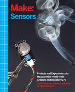
A vibration sensor can detect tiny vibrations, like the ground shaking (Figure 6-4).

Vibration Code and Connection for Arduino
The signal sent by a vibration sensor is very short. You must use an interrupt to catch it.
For most sensors, you could just poll them. Polling means that you check the state of the digital pin, wait a while, and then check again.
With an interrupt, you can tell Arduino to run a function whenever some event happens. Interrupts make it harder to follow the flow of the code you write, but they allow you to catch very short-lived events, like a pin going up and then down quickly.
Figure 6-5 shows the circuit diagram for the vibration sensor. Wire it up as shown, and then run the code shown in Example 6-3.

// vibration_sensor.ino - detect vibration using interrupt// (c) BotBook.com - Karvinen, Karvinen, ValtokariconstintsensorPin=0;//UNO,Mega pin 2, Leonardo pin 3volatileintsensorState=-1;voidsetup(){Serial.begin(115200);attachInterrupt(sensorPin,sensorTriggered,RISING);//}voidloop(){if(sensorState==1){//Serial.println("Vibrations detected");delay(1);// mssensorState=0;}delay(10);}voidsensorTriggered(){//sensorState=1;//}
-
This tells Arduino to call
sensorTriggered()whensensorPingoes from LOW to HIGH. This is known as a callback. Notice that the name of the function in the callback does not have parentheses after it. Without the parentheses, a function name is a pointer to the function (whereas including the parentheses would cause the function to be called once and return its value). After all,attachInterrupt()needs to know about the function, and isn’t ready to run it yet.-
The main loop can go on its merry way as slowly as it wants. It checks the value of a global variable.

When the interrupt is triggered,
sensorTriggered()is called. The interrupt reacts very quickly.
The
sensorTriggered()function simply sets a global variable, which can be read at the main loop’s leisure.
Vibration Code and Connection for Raspberry Pi
Figure 6-6 shows the wiring diagram for the Raspberry Pi version of this sensor circuit. Wire it up as shown and then run the program shown in Example 6-4.
# vibration_sensor.py - detect vibration# (c) BotBook.com - Karvinen, Karvinen, Valtokariimporttimeimportbotbook_gpioasgpio#defmain():vibPin=3gpio.mode(vibPin,"in")while(True):vibrationInput=gpio.read(vibPin)#if(vibrationInput==gpio.LOW):"Vibration"time.sleep(5)#time.sleep(0.01)# seconds #if__name__=="__main__":main()
-
As with previous examples, this library must be in the same directory along with vibration_sensor.py.
-
The vibration sensor is used like a digital switch sensor. You can read it like a button.
-
If vibration was detected, report it only once instead of filling the screen with “Vibration” texts.
-
We use a very short 10 ms delay, so
vibPinis polled 100 times a second (100 Hz).
Raspberry Pi code can’t detect as short vibrations as Arduino can. The code doesn’t use an interrupt, because it would complicate the code, would still need fast looping, and still couldn’t match Arduino. If you need very precise vibration detection in Raspberry Pi, you can connect Arduino to Raspberry Pi (Talking to Arduino from Raspberry Pi).
Experiment: Turn the Knob
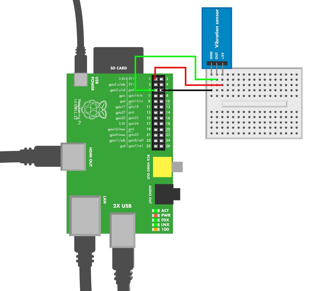
A rotary encoder measures turning (see Figure 6-7). An absolute rotary encoder tells the position (position is 83 deg), and relative rotary encoders tell the change (turned 23 deg from previous position).
The rotary encoder we use here is a relative one. When you turn the knob, the encoder sends clock pulses on the clock pin. On the rising edge (the clock goes from LOW to HIGH), one data pulse comes on the data pin; another comes on the falling edge (HIGH to LOW transition).
If the data pulse is HIGH, you’re turning right (clockwise, negative direction). If the data pulse is LOW, you’re turning left.

Rotary Encoder Code and Connection for Arduino
This code uses interrupts, so it might look different from the Arduino codes you’ve worked with before. Wire up the circuit as shown in Figure 6-8, and run the sketch shown in Example 6-5.
// rotary_encoder.ino - print encoder position// (c) BotBook.com - Karvinen, Karvinen, ValtokariconstintclkPin=2;constintdtPin=4;volatileunsignedintencoderPos=0;//voidsetup(){Serial.begin(115200);pinMode(clkPin,INPUT);digitalWrite(clkPin,HIGH);// pull up //pinMode(dtPin,INPUT);digitalWrite(dtPin,HIGH);// pull upattachInterrupt(0,processEncoder,CHANGE);//}voidloop(){Serial.println(encoderPos);delay(100);}voidprocessEncoder()//{if(digitalRead(clkPin)==digitalRead(dtPin))//{encoderPos++;// turning right}else{encoderPos--;}}
-
EncoderPosis marked as volatile, because it’s modified in the interrupt function. The volatile keyword lets the Arduino compiler know that the value could change “behind the back” of the main loop of the Arduino sketch.-
Writing
HIGHto anINPUTpin connects it to +5 V through a 20 kOhm pull-up resistor. This is done to avoid a floating pin.-
Anytime there is
CHANGE(rising or falling edge), call the functionprocessEncoder. In Arduino Uno, interrupt 0 monitors digital pin 2. The callback functionprocessEncoderdoesn’t have parentheses after it, because it’s not needed to run yet. It will run later, when called by the interrupt (this happens behind the scenes).-
Anything else is put on hold while the interrupt function runs.

When
dtPinis in the same state as the clock pin, it indicates a right turn. Otherwise, it’s a left turn.
Rotary Encoder Code and Connection for Raspberry Pi
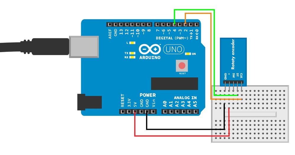
Figure 6-9 shows the wiring diagram for using a rotary encoder with Raspberry Pi. Wire it up as shown and then run the program shown in Example 6-6.
# rotary_encoder.py - read rotary encoder# (c) BotBook.com - Karvinen, Karvinen, Valtokariimporttimeimportbotbook_gpioasgpio#defmain():encoderClk=3encoderDt=2gpio.mode(encoderClk,"in")gpio.mode(encoderDt,"in")encoderLast=gpio.LOWencoderPos=0lastEncoderPos=0whileTrue:clk=gpio.read(encoderClk)ifencoderLast==gpio.LOWandclk==gpio.HIGH:#if(gpio.read(encoderDt)==gpio.LOW):#encoderPos+=1else:encoderPos-=1encoderLast=clkifencoderPos!=lastEncoderPos:("Encoder position%d"%encoderPos)lastEncoderPos=encoderPostime.sleep(0.001)# s #if__name__=="__main__":main()
-
Make sure there’s a copy of the botbook_gpio.py library in the same directory as this program. You can download this library along with all the example code from http://botbook.com. See GPIO Without Root for information on configuring your Raspberry Pi for GPIO access.
-
If a rising edge (LOW to HIGH) is detected…
-
…when data is LOW on the clock edge, the encoder is turning left (counterclockwise, positive direction).
-
Sleep only 1 millisecond, so that we don’t miss any clicks.
Even though the Raspberry Pi has more processing power, Arduino is much faster (as in more real time). If you feel that Raspberry Pi is missing too many pulses when you turn fast and run a lot of other software on your Raspberry, consider reading the pulses through an Arduino. See Talking to Arduino from Raspberry Pi.
Experiment: Thumb Joystick (Analog Two-Axis Thumb Joystick)
If you’ve played on any videogame consoles, you have used a joystick. In the old days, you grabbed a big joystick with your strong hand. Modern gaming consoles like Xbox, PlayStation, or Ouya use multiple thumb joysticks.
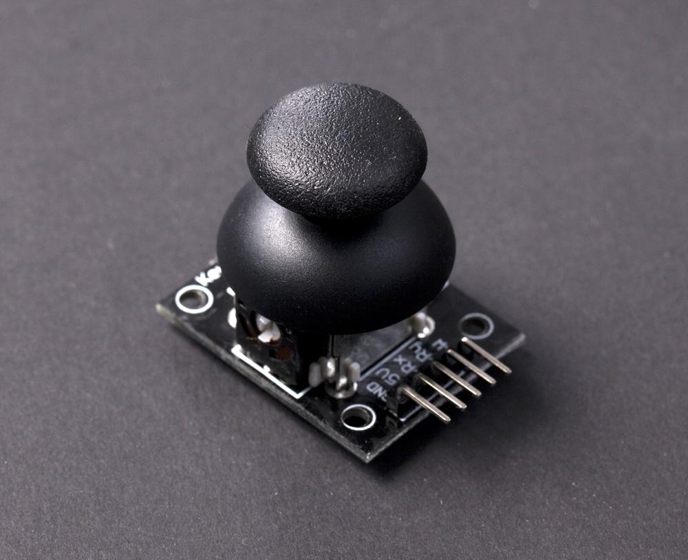
Typically, a joystick has two potentiometers (pots), which are variable resistors. Tilting the joystick along the vertical y-axis changes the resistance of one pot. Tilting along the horizontal x-axis changes the resistance of another pot.
In many joysticks, the potentiometers are in three-lead configuration. They have one lead on the ground, another on +5 V, and one in the middle, giving a varying voltage between 0 V and +5 V. In this three-lead configuration, no pull-up or pull-down resistors are needed.
Mobile phones and Wii consoles can use accelerometers instead of joysticks. The device attitude is measured against gravity and is used for controlling games. (See Experiment: Hacking Wii Nunchuk (with I2C).) Gravity has the same effect as acceleration. To get precise attitude measurements, see Chapter 8.
Joystick Code and Connection for Arduino
Figure 6-11 shows the circuit design for using Arduino with a joystick. Wire it up and run the sketch shown in Example 6-7.

// ky_023_xyjoystick.ino - print joystick position to serial// (c) BotBook.com - Karvinen, Karvinen, ValtokariconstintVRxPin=0;//constintVRyPin=1;constintSwButtonPin=8;intbutton=-1;// LOW or HIGH //intx=-1;// 0..1023inty=-1;// 0..1023voidreadJoystick(){//button=digitalRead(SwButtonPin);//x=analogRead(VRxPin);y=analogRead(VRyPin);}voidsetup(){pinMode(SwButtonPin,INPUT);digitalWrite(SwButtonPin,HIGH);// pull-up resistor //Serial.begin(115200);}voidloop(){readJoystick();//Serial.("X:");Serial.(x);Serial.("Y:");Serial.(y);Serial.("Button:");Serial.println(button);delay(10);}
-
Store the pin numbers into global constants: a variable resistor for x, a variable resistor for y, and a button.
-
These global variables store the state of the button and the tilt of the joystick along y- and x-axes. We initialize these variables to impossible values (values that won’t get generated by calls to
analogReadordigitalRead) to help debugging. The intended range of values is indicated in the comments.-
readJoystick()doesn’t return a value (it’s said to be of a void type). In C++, which Arduino is based on, functions can’t conveniently return multiple values. Instead,readJoystick()updates global variables.-
The button state is stored to the global variable
button.-
Enable the internal pull-up resistor to avoid having a floating pin.

Update the global variables that store the joystick state.
Joystick Code and Connection for Raspberry Pi
Figure 6-12 shows the circuit layout for Raspberry Pi and a joystick. Hook everything up as shown, and then run the program shown in Example 6-8.

# xy_joystick.py - print KY 023 joystick tilt and button status# (c) BotBook.com - Karvinen, Karvinen, Valtokariimporttimeimportbotbook_mcp3002asmcp#importbotbook_gpioasgpio#defreadX():#returnmcp.readAnalog(0,0)defreadY():returnmcp.readAnalog(0,1)#defreadButton():buttonPin=25gpio.mode(buttonPin,"in")returngpio.read(buttonPin)defmain():whileTrue:#xAxel=readX()#yAxel=readY()button=readButton()("X:%i, Y:%i, Button:%r"%(xAxel,yAxel,button))#time.sleep(0.5)if__name__=="__main__":main()
-
Import the library for the MCP3002 analog-to-digital converter chip. The library botbook_mcp3002.py must be in the same directory as xy_joystick.py. You must also install the spidev library, which is imported by botbook_mcp3002. See comments in the beginning of botbook_mcp3002/botbook_mcp3002.py or Installing SpiDev.
-
Use more convenient namespace to keep the code from getting too verbose. The
askeyword allows you to writegpio.read()instead ofbotbook_gpio.read().-
Write functions according to their purpose. The purpose of
readX()(read the state of the x-axis) will look obvious in the main program.-
Measure the voltage on the second channel (number 1).
-
Keep running until you hit Control-C to kill the program (or shut down the Raspberry Pi).
-
Read the tilt along the x-axis and store it to new variable
xAxel.
When using multiple variables in a format string, the variables must be in a tuple (a group of values separated by commas). You can think of a tuple
(1, 2, 3)as a list[1, 2, 3]that you can’t modify.
Environment Experiment: Salvage Parts from an Xbox Controller
If you have an old game console (Xbox, PlayStation, etc.) control pad lying around, you can salvage two sensors from it and use them with your Arduino or Raspberry Pi (Figure 6-13). Opening the controller is quite easy, but you’ll need to use a soldering iron to detach the components from the circuit board.
For detaching components, you may also find these tools/supplies helpful: a desoldering pump, solder wick (also known as a braid), or even a flux pen.
Many controllers also have a simple force feedback system. For example, if a player takes damage in a game, force feedback makes the controller shake. This is done with vibration motors—eccentric DC motors that spin and shake when powered. Take these out, too, and give them a new home in your own force feedback gadget (Figure 6-14).


Experiment: Burglar Alarm! (Passive Infrared Sensor)
A passive infrared (PIR) sensor is probably the most common burglar alarm. All warm objects radiate invisible infrared light. A PIR sensor reacts to changing infrared light. This change is typically caused by a warm human moving.
Be sure to let your PIR sensor adapt to its environment first. Because a PIR only detects change, it has to first know the heat pattern in the room when there is no burglar. After you turn on the power, the PIR sensor needs 30 seconds to adapt to the environment. There must be no movement or people in the watched area during the adaptation period.
You can use a box to limit the area watched by a PIR sensor. When you want to quickly test a PIR sensor, put it in an upside-down box, so that it can only see upward. While the PIR sensor learns what the environment looks like, you can keep writing code without needing to be absolutely still. When you want to send an alarm to test your code, wave your hand above the box.
The Parallax PIR has two modes of operation:
- H for stay High as long as there is movement
- L for return to Low after an alarm
So in L mode, the PIR just sends one pulse even if movement continues after it’s first detected.
The PIR has a tiny jumper wire to choose the mode of operation. The jumper is a tiny rectangular part covered in black plastic. In this project, set the jumper to H (stay High) mode.
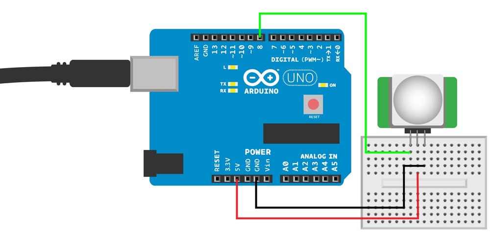
Burglar Alarm Code and Connection for Arduino
Figure 6-15 shows the circuit diagram for Arduino. Wire it up and run the sketch shown in Example 6-9.
// parallax_pir_reva.ino - print movement detection// (c) BotBook.com - Karvinen, Karvinen, ValtokariconstintsensorPin=8;constintledPin=13;constintlearningPeriod=30*1000;// ms //intlearningCompleted=0;voidsetup(){Serial.begin(115200);pinMode(sensorPin,INPUT);Serial.println("Starting to learn unmoving environment...");//pinMode(ledPin,OUTPUT);}voidloop(){if(millis()<learningPeriod){//delay(20);// ms //return;//}if(learningCompleted==0){//learningCompleted=1;Serial.println("Learning completed.");}if(digitalRead(sensorPin)==HIGH){//Serial.println("Movement detected");digitalWrite(ledPin,HIGH);}else{Serial.println("No movement detected");digitalWrite(ledPin,LOW);}delay(100);}
-
The PIR needs movement-free time to adapt. Here, we use 30,000 ms (30 seconds). The value is stored into a global constant. Avoid the temptation to repeat the value in the comment. Instead, use your comment to tell the unit (milliseconds) of the variable. That way, if you change a value, you don’t need to change the comment. Also, if the standard unit version of the value (seconds) is a result of a calculation (number of seconds * 1000), write the calculation into code (
30*1000).-
Print instructions to serial. To open the serial monitor, use Tools→Serial Monitor. Remember to choose the same speed (“baud”, bit/s) in both the serial monitor and your code.
-
This is a common pattern to measure time in Arduino. The
millis()function returns milliseconds since last boot.-
A short delay prevents repeated calls to
loop()from consuming 100% of CPU time.-
A return statement finishes the
loop()function. As always, afterloop()finishes, it’s automatically called again.-
The
learningCompletedvariable ensures that you print “Learning completed” only once. Here, 1 and 0 are used like true and false.-
When PIR detects warm movement,
sensorPingoes HIGH.
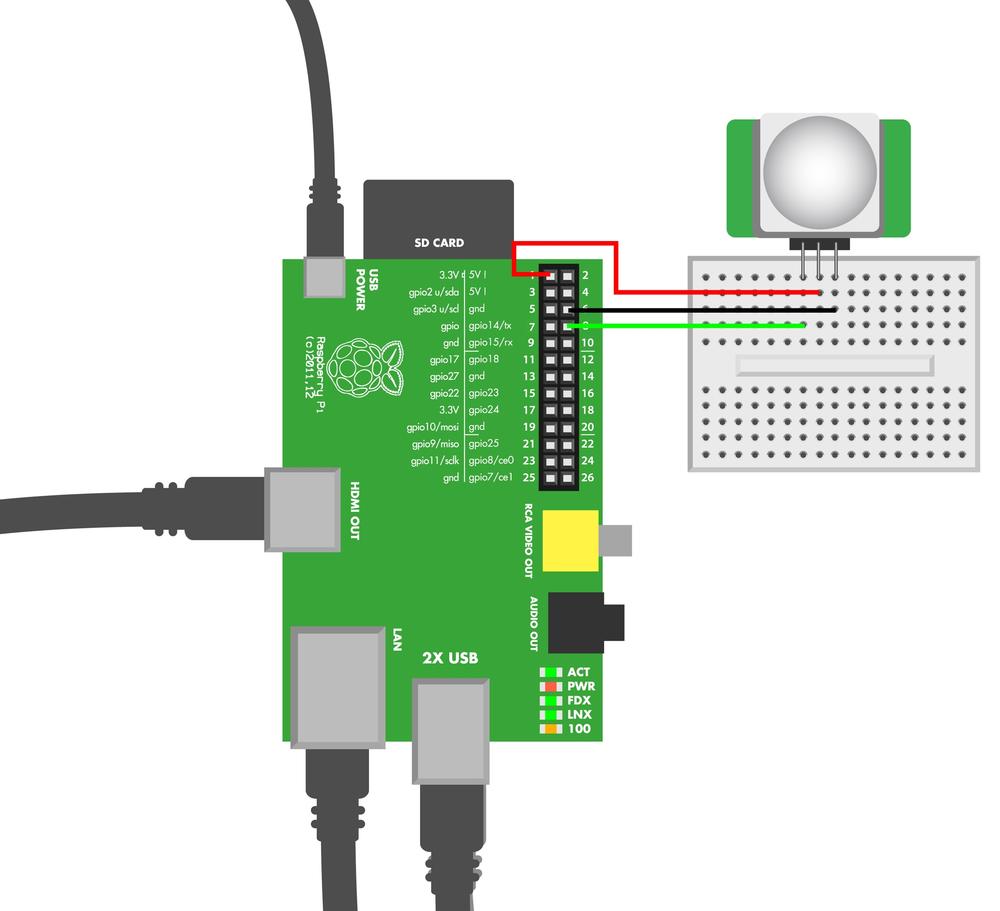
Burglar Alarm Code and Connection for Raspberry Pi
Figure 6-16 shows the circuit for Raspberry Pi. Wire it up as shown, and then run the code in Example 6-10.
# parallax_pir_reva.py - write to screen when movement detected# (c) BotBook.com - Karvinen, Karvinen, Valtokariimporttimeimportbotbook_gpioasgpiolearningPeriod=60defmain():pirPin=14gpio.mode(pirPin,"in")#Learning periodtime.sleep(learningPeriod)#while(True):movement=gpio.read(pirPin)#if(movement==gpio.HIGH):"Movement detected"else:"No movement detected"time.sleep(0.3)if__name__=="__main__":main()
-
The sensors need movement-free time to adapt. Here we use 60 seconds, but you can experiment with different times.
-
The pin goes HIGH when movement is detected.
Environment Experiment: Cheating an Alarm
Sometimes a penetration tester (a security expert who probes for vulnerabilities) must move by alarms unnoticed. In this experiment, you can practice in the privacy of your home. This way, you don’t have to worry about customers watching (if you are a professional pentester) or a lifetime of free room and board with no way to check out (if you dream of a criminal career).

You can try cheating your PIR sensor, but as you will soon notice it’s not quite as easy as in action films. We’ll use the same code as before but add a piezo beeper. This way, it’s easier to know when movement is detected. Connect the piezo according to the circuit diagram in Figure 6-18 and upload the code in Example 6-11.

// parallax_PIR_revA_cheating_pir.ino - light an LED when movement detected// (c) BotBook.com - Karvinen, Karvinen, ValtokariconstintsensorPin=8;constintledPin=13;intspeakerPin=10;constintlearningPeriod=30*1000;// 30 seconds for learning period.intlearningCompleted=0;voidsetup(){Serial.begin(115200);pinMode(speakerPin,OUTPUT);pinMode(sensorPin,INPUT);Serial.println("Start learning for next 30 seconds.");pinMode(ledPin,OUTPUT);}voidalarm(){wave(speakerPin,440,40);delay(25);wave(speakerPin,300,20);wave(speakerPin,540,40);delay(25);}voidwave(intpin,floatfrequency,intduration){floatperiod=1/frequency*1000*1000;// microseconds (us)longintstartTime=millis();while(millis()-startTime<duration){digitalWrite(pin,HIGH);delayMicroseconds(period/2);digitalWrite(pin,LOW);delayMicroseconds(period/2);}}voidloop(){if(millis()<learningPeriod){return;// Sensor has not yet learned its environment.}if(learningCompleted==0){learningCompleted=1;Serial.println("Learning completed.");}if(digitalRead(sensorPin)==HIGH){Serial.println("Movement detected");alarm();digitalWrite(ledPin,HIGH);}else{Serial.println("No movement detected");digitalWrite(ledPin,LOW);}delay(100);}
Now you should hear an alarm when you move your hand before the sensor. Try to approach the PIR from a few meters away without triggering it. You’ll have to move really slowly, and even then, it’s hard. Using a bed sheet or a big towel makes it much easier. Fully cover yourself, cartoon ghost style (no eye holes, though!) and slowly start moving toward the sensor. Covering yourself limits the sensor’s ability to detect your body heat radiation. This way, you could almost touch the sensor before it notices you.
In real-life physical pentesting, you must work with movement alarms that combine ultrasonic distance sensing to passive infrared. And of course, security cameras automatically detect changes in the picture.
You already learned how to confuse an ultrasonic distance sensor in Environment Experiment: Invisible Objects. Even though cameras can be difficult to cheat, you can sneak in between cameras. Many cameras use active infrared illumination to see in the dark. You learned how to see infrared light in Environment Experiment: How to See Infrared.
Test Project: Pong
Detecting movement is much more interesting when you can actually present that information to the user. In this project you’ll learn how to use sensor data to move objects on the screen. To keep things simple, we use a joystick as an input for a Pong game in this example. What you learn here can be easily adapted to other projects. Any sensor could be the input device, and only your imagination limits what is shown on the screen.

Pong, originally manufactured by Atari in 1972, is the classic game where you move a paddle up and down. Your goal is to keep the ball out of your goal. See <<[pong-game>>.
This project introduces you to pyGame, one of the easiest libraries for programming games. You’ll build your own game console and learn to use sensor input for moving things in the big screen. For added effect, use a video projector for output.
This project is easy to do with Raspberry Pi, as you can connect your normal television or video projector to Raspberry Pi’s HDMI connector. Doing the same in Arduino would not be as straightforward.
That’s not to say it would be impossible. Pong comes from a time when CPUs were slower and had less RAM than the Arduino. They would draw scan lines on a screen and perform their computations during the horizontal and vertical blank. See http://bit.ly/1f0GgHt for a simple Arduino Pong project. If you want to make all kinds of old-fashioned video games with Arduino, check out the Video Game Shield from Wayne and Layne.

What You’ll Learn
In the Pong project, you’ll learn how to:
- Use data from a sensor to move objects on the screen.
- Display full high-def graphics with Raspberry Pi.
- Make Raspberry Pi react faster by drawing directly to screen, without going through the desktop environment or the X Window System.
- Program a simple game with Python’s pyGame.
- Automatically start your program when Raspberry Pi boots.
Figure 6-21 shows the wiring diagram for the Pong project. Wire it up as shown, and then run the program shown in Example 6-12. Be sure that the botbook_gpio.py library is in the same directory as the pong.py program.

# pong.py - play ball game classic with joystick and big screen# (c) BotBook.com - Karvinen, Karvinen, Valtokariimporttimeimportsysimportpygameimportbotbook_gpioasgpiofrompygame.localsimport*"Loading BotBook.com Pong..."pygame.init()#width=pygame.display.Info().current_w#height=pygame.display.Info().current_hsize=width,height#background=0,0,0#screen=pygame.display.set_mode(size,pygame.FULLSCREEN)#normalSpeed=512ballrect=Rect(width/2,height/2,16,16)#computerrect=Rect(width-20,0,20,120)#playerrect=Rect(0,0,20,120)##movement is diff in x and y. ball can only move in 45 degree angles.speed=[normalSpeed,normalSpeed]#clock=pygame.time.Clock()#pygame.mouse.set_visible(False)mainloop=Trueuppin=2downpin=3gpio.mode(uppin,"in")gpio.mode(downpin,"in")whilemainloop:#seconds=clock.tick(30)/1000.0# seconds since last frame ## User inputforeventinpygame.event.get():#ifevent.type==pygame.QUIT:mainloop=False#if(event.type==KEYUP)or(event.type==KEYDOWN):ifevent.key==K_ESCAPE:mainloop=False# Movement and collisionsplayerspeed=0ifgpio.read(uppin)==gpio.LOW:playerspeed=-normalSpeedifgpio.read(downpin)==gpio.LOW:playerspeed=normalSpeedballrect.x+=speed[0]*seconds#ballrect.y+=speed[1]*secondsifballrect.left<0orballrect.right>width:#ballrect.x=width/2;ifballrect.top<0orballrect.bottom>height:speed[1]=-speed[1]computerrect.y=round(ballrect.y)#playerrect.y+=playerspeed*seconds#ifplayerrect.top<0:playerrect.top=0#ifplayerrect.bottom>height:playerrect.bottom=height#ifcomputerrect.colliderect(ballrect):#speed[0]=-normalSpeedifplayerrect.colliderect(ballrect):speed[0]=normalSpeed# Draw framescreen.fill(background)pygame.draw.circle(screen,(255,255,255),(int(round(ballrect.x+8)),int(round(ballrect.y+8))),10)#pygame.draw.rect(screen,(255,255,255),computerrect)#pygame.draw.rect(screen,(255,255,255),playerrect)pygame.display.update()#
-
For pyGame to work, you must first initialize it.
-
PyGame uses predefined dimensions for canvas. This allows you to work with actual pixels onscreen, instead of some intermediate units. These two lines retrieve the width and height.
-
The canvas size is specified as a tuple:
(width, height).-
Colors in pyGame are red, green, and blue (RGB). You’ve probably worked with RGB colors if you have ever specified colors for web pages.
(0, 0, 0)is black.-
screenis the object where the actual drawing will happen. It will be used near the end of the main loop.-
Create bounding rectangles for onscreen objects in the game:
Rect(x, y, width, height). The ball starts from the top-left corner (y==0, x==0). The ball’s bounding rectangle size is 16 × 16 pixels.-
This places the computer player’s paddle near the right edge of the canvas. The paddle is 20 pixels (px) thick and 120 px tall.

The human player’s paddle starts from top left (0,0). Its dimensions are 20 × 120 pixels, like the computer’s paddle.

The speed vector for the ball. Each second, the ball will move 64 pixels on the x-axis and 64 pixels on the y-axis.

Create a new
Clockobject, and store it into the newly declared variableclock. This will be used for keeping the speed consistent even if you’ve overclocked your Raspberry Pi.
PyGame uses a main loop programming style. Main loop is a very common pattern in games. Just like the typical Arduino
loop()or thewhile(True)you’ve seen in Python examples, the main loop starts over each time it completes. Typical game main loop tasks include getting user input, moving objects on the screen, checking for collisions, and finally, drawing one frame on the screen.
clock.tick()returns the time since its last call. When you call it once in a frame (once every main loop run), you get the elapsed time since the last frame. The parameter 60 specifies a maximum frame rate of 60 Hz, that is, 60 frames per second. If the game is going faster,tick()will wait before returning. For more human-friendly units, we convert the milliseconds (1/1000 s) returned bytick()to seconds.
Keyboard input is handled through the
pygame.eventobject. Thepygame.event.get()returns an object of events that contains a collection of items that you can iterate over. The “for ITEM in LIST” loop goes through the LIST one at a time. It sets ITEM to be the first item in LIST in the first iteration, then the second in the list in the second iteration, and so forth until it is finished.
Compare each individual event to predefined pyGame constants, and react if it matches. For example, if the user performs a user interface action that would quit the game, the QUIT event comes through, and it’s time to exit.

Move the ball. Because we account for elapsed time each frame, it will move at the same 64 pixels per second despite changes in frame rate.

If the ball hits the limits of playing field, bounce!

Move the computer paddle to exactly the same height as the ball. You have one tough opponent here!

Move the player paddle vertically according to acceleration from the input keys. The shorthand
a+=2means the same asa=a+2.
If a player’s movement would take the paddle through the top of the canvas, just stay on the top.

If a player’s movement would take the paddle through the bottom of the canvas, just stay put.

Check to see if the ball collided with either paddle. If so, set the ball’s direction to a direction away from the paddle it collided with.

Draw the ball at its calculated position.

The computer paddle is drawn at the location calculated earlier. As its shape is a rectangle, the bounding box is exactly the same as the object itself.

Show everything in this frame, all at the same time.
Pong Packaging Tips
We used a diecast aluminum box to make a super robust casing with street credibility for our game console (Figure 6-22). This construction makes an attractive alternative to the flimsy plastic gadgets we usually see and use.
In the back of the box, we made a hole for power and HDMI cables (Figure 6-23). To make a wide hole like ours, drill two large holes separately and then remove the metal in between with a jigsaw blade.
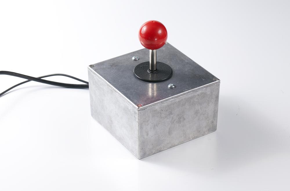

A traditional arcade joystick makes a perfect match for the indestructible box (Figure 6-24). To attach the joystick, you need three holes: two 5 mm to mount the frame and one 10 mm to get the actual stick through the cover (Figure 6-25).


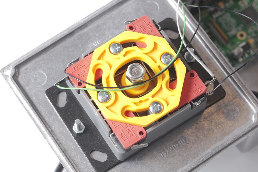
As we are going to control only up and down movement, we need to solder wires to two of the joystick’s microswitches, as shown in Figure 6-26.
Raspberry Pi was attached simply by hot gluing the Raspberry Pi’s cover box bottom to the bottom of our aluminum box (see Figure 6-27).

Automatically Start Your Game When Raspberry Pi Boots
Now that you have a beautifully packaged game console of your own, it’s time to have another look at user experience. Wouldn’t it be nice if the game started on boot? Without a keyboard, it’s difficult to type python pong.py each time you want to start the game.
To start the game as a normal user, you’ll set the system to log in as the user pi automatically. Then you’ll configure things to start the game in the user’s login script. This way, the game starts immediately when you boot Raspberry Pi.
Run Game on Login
When you log in, bash opens. Bash is your shell: it interprets the commands that you type at the command prompt ($).
If your Raspberry Pi automatically boots into the graphical desktop (the default), you should change it to start up in a text mode shell, because you need to run it from text mode in order for it to run automatically on login. Open LXTerminal and run sudo raspi-config. There you can choose Enable Boot To Desktop and choose Console Text console.
The first thing that bash does is to run scripts, such as .profile, .login, .bash_profile, and .bash_login. Just like all per-user configuration files, they are hidden files in the user home directory. To see them, you must use the -a flag with ls. If you’re not already in your home directory, you can quickly change to it (/home/pi/) with cd without arguments. Here’s a set of commands (don’t type the $, since that’s the shell prompt) that change to your home directory and list all the files there:
$ cd
$ ls -a
The .bash_login file is a shell script: it has commands to run, one after another. Before you add this command to the file, try it out on the command line:
$ python /home/pi/makesensors/pong/pong.py
Replace makesensors with the path where you have put the pong.py program. Press Esc to quit the game. If everything worked OK, you can now open the .bash_login file with the nano editor:
$ nano .bash_login
Add the line python /home/pi/makesensors/pong/pong.py to .bash_login. If there are any other lines already in the file, delete them. Example 6-13 shows what the .bash_login file should now look like. Save the file by typing Control-X, then press y when prompted to Save, and finally type Enter/Return to confirm the filename.
# /home/pi/.bash_login - automatically start pong game on loginpython/home/pi/makesensors/pong/pong.py
Log out:
$ exit
Next, log back in. The game starts automatically.
Automatic Login
Now it’s time to make your user “pi” log in automatically on boot. Because the game runs immediately after “pi” logs in, this will start the game after you power up the Pi. If you’re still in the game, press Esc to escape from it.
The init program controls system boot, so you will need to modify its settings. All system-wide settings are in /etc/, and the configuration file usually starts with the name of the thing: /etc/init* (in this case, /etc/inittab). Because logging users in is a process that requires full privileges, you need to edit the file as root with the sudoedit command:
$ sudoedit /etc/inittab
To edit text files as root, you use sudoedit instead of using nano with sudo. This way, you won’t get errors about nano’s history file ownership when using nano as a normal user later.
Modify the line that governs the first “virtual terminal” so that it automatically logs you in (don’t add this line, modify the one that starts with 1:2345:respawn:/sbin/getty):
1:2345:respawn:/sbin/getty --noclear 38400 tty1 --autologin pi
Save with Control-X, answer y when asked about saving, and then press Enter or Return to confirm the filename. You can see a complete, modified /etc/inittab in Example 6-14.
Shut down the Raspberry Pi:
$ sudo shutdown -P now
Then disconnect and reconnect USB power.
Relax as you are automatically logged in. The game starts, and your very own game console is ready. Time to play Pong!
# /etc/inittab - automatically log in user pi on boot (also disable serial)id:2:initdefault:si::sysinit:/etc/init.d/rcS~~:S:wait:/sbin/suloginl0:0:wait:/etc/init.d/rc0l1:1:wait:/etc/init.d/rc1l2:2:wait:/etc/init.d/rc2l3:3:wait:/etc/init.d/rc3l4:4:wait:/etc/init.d/rc4l5:5:wait:/etc/init.d/rc5l6:6:wait:/etc/init.d/rc6z6:6:respawn:/sbin/suloginca:12345:ctrlaltdel:/sbin/shutdown-t1-a-rnowpf::powerwait:/etc/init.d/powerfailstartpn::powerfailnow:/etc/init.d/powerfailnowpo::powerokwait:/etc/init.d/powerfailstop# modified:1:2345:respawn:/sbin/getty--noclear38400tty1--autologinpi2:23:respawn:/sbin/getty38400tty23:23:respawn:/sbin/getty38400tty34:23:respawn:/sbin/getty38400tty45:23:respawn:/sbin/getty38400tty56:23:respawn:/sbin/getty38400tty6# removed serial console, so that serial port can be used with sensors:# T0:23:respawn:/sbin/getty -L ttyAMA0 115200 vt100
Run as normal user whenever possible. Only perform system administration (e.g., apt-get, raspi-config) as root. It’s especially important that games run as a normal user because they often need direct access to hardware, and programs that reach deeper into your system can do more damage if they have a serious bug. That’s why you should use autologin and login script to start the game (as described here), instead of simply putting the game into a startup script such as rc.local (which always runs as root).
To stop playing and return to the command line, just press Esc.
You have now tested movement in many ways, starting from basic buttons and potentiometers. These sensors are the archetypes of resistance sensors. The button is the simplest digital (on/off or zero/infinite resistance) resistance sensor, and the potentiometer is the simplest analog resistance sensor. You’ll be able to use similar circuits and code with many other sensors.
For more specialized sensors, you’ve detected touch—even through wood. And you’ve measured pressure, which could be useful in your projects to see if a bed or a seat is occupied, or just to have a finger strength competition.
Next, you’ll measure a less tangible form of energy: light.