Chapter 5. Touch
In this chapter, you’ll meet a button, a squeeze sensor, and a capacitive touch sensor. You’ll learn to use pull-up resistors to avoid floating pins. Finally, you’ll build a haunted bell to try your touch skills in a project.
A button is the most basic sensor, so it’s also the most basic touch sensor. When a button is pressed, its leads are connected, closing a circuit. A microswitch is a type of small, durable button.
A FlexiForce sensor detects how much force is being put on it. You can use it to test the might of your fingers or to detect when someone is sitting on a chair.
A touch sensor senses touch without any moving parts. And the weird part of a touch sensor is that it doesn’t even require touch! You’ll learn to detect a hand placed on a table, through the table.
Even though touch sensors serve a similar purpose in your projects, their methods of measuring touch differ. A button simply connects two wires. The FlexiForce pressure sensor is based on thin layers of pressure-sensitive ink. A touch sensor measures capacitance—the ability to store electricity.
Experiment: Button
Light up an LED when a button is pressed.
A button (Figure 5-1) is the simplest sensor. Pressing the button down connects its leads, so that the button acts as a wire. Releasing the button breaks the circuit. All digital switch sensors (such as a reed switch or tilt switch) work like a button.

Buttons come in many sizes and forms. When using a breadboard, it’s convenient to use a button with four leads. The leads are in pairs, so that two adjacent leads are always connected to each other. When you turn the button upside-down, you can see which leads are connected. There is a beveled line showing the connected leads (Figure 5-2).

Pull-Up Resistor
To get a reading from a data pin, it must be connected somewhere. You should not read an unconnected floating pin. A pull-up resistor pulls a pin HIGH when it’s not connected to anything else, avoiding the floating state.
The state of a data pin can be read with commands such as digitalRead(), analogRead(), botbook_gpio.read(), botbook_mcp2003.readAnalog().
A pin that’s connected to ground or HIGH is an obvious case: when you read its state, it’s clear which state it’s in. If the pin is connected to ground (GND, 0 V), a digital read returns LOW. If the pin is connected to HIGH (+5 V or +3.3 V), the read returns HIGH.
If you read an unconnected, floating data pin, you would get an undefined value. It could be HIGH, it could be LOW, it could change every second or stay the same forever. Such an undefined value is completely useless, so there is no point in reading a floating pin.
Consider a circuit with a button between a data pin and ground (Figure 5-3). When the button is pressed, the data pin is connected to ground so it’s LOW.
What about when the button is up? You must use a pull-up resistor to bring the data pin HIGH.
The pull-up resistor is big. We often use one in the tens of thousands ohms range. This way, when the button is pressed and the data pin is connected to both ground and the pull-up, there is no short-circuit between +5 V and ground because the path of least resistance is between the data pin and ground, rather than between +5 V and ground.
For convenience, the code below uses built-in pull-up resistors. For Arduino, you can enable the onboard pull-up resistors with a line of code. For Raspberry Pi, you’ll use one of the pins that has an always-on pull-up resistor.
Code and Connection for Arduino
Build the circuit shown in Figure 5-3 and upload the code shown in Example 5-1. Press the button to light up the surface-mounted LED.
If pressing the button doesn’t affect the LED at all, check that you have connected the button the right way.

// button.ino - light an LED by pressing a button// (c) BotBook.com - Karvinen, Karvinen, ValtokariintbuttonPin=2;intledPin=13;intbuttonStatus=-1;voidsetup(){pinMode(ledPin,OUTPUT);pinMode(buttonPin,INPUT);//digitalWrite(buttonPin,HIGH);// internal pull-up //}voidloop(){buttonStatus=digitalRead(buttonPin);//if(LOW==buttonStatus){//digitalWrite(ledPin,HIGH);//}else{digitalWrite(ledPin,LOW);}delay(20);//}

Put the pin in INPUT mode to be able to check its voltage with
digitalRead()later.
Connect the D2 pin to GND with large (20 kilohm) internal resistor. This prevents the pin from floating when the button is open. The internal pull-up resistors save you the trouble of connecting an extra resistor to your breadboard. The latest versions of Arduino offer a new option for
pinMode(),INPUT_PULLUP, which allows you to combine this line and the preceding line into a single command:pinMode(buttonPin, INPUT_PULLUP);. But the older method works fine and you will still see it in many example programs written before the new mode was introduced.
Read the voltage of D2. HIGH means +5 V, LOW means 0 V, ground level.

If the button level is LOW (meaning the button is pressed down)…

…light up an LED. Data pin D13 is connected to surface mounted LED on the Arduino.

Pause briefly to not overtax the CPU.
This code keeps the LED lit when the button is held down. If you want to instead toggle the LED each time you press the button, you must debounce the input. For example, creating a device where one click turns the LED on and the next turns it off requires debouncing. You can find a debounce example program in the Arduino IDE under File→Examples→2.Digital: Debounce.
Code and Connection for Raspberry Pi
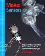
Wire up the Raspberry Pi as shown in Figure 5-4 and run the Python program shown in Example 5-2.
# button.py - write to screen if button is down or up# (c) BotBook.com - Karvinen, Karvinen, Valtokariimporttimeimportbotbook_gpioasgpio#defmain():buttonpin=3# has internal pull-up #gpio.mode(buttonpin,"in")#while(True):#buttonUp=gpio.read(buttonpin)#if(buttonUp==gpio.HIGH):"Button is up"else:"Button is pressed"time.sleep(0.3)# seconds #if__name__=="__main__":main()
-
Make sure there’s a copy of the botbook_gpio.py library in the same directory as this program. You can download this library along with all the example code from http://botbook.com. See GPIO Without Root for information on configuring your Raspberry Pi for GPIO access.
-
The gpio3 pin has an internal pull-up resistor—it’s connected to +3.3 V through an 1800 Ohm resistor.
-
Set gpio3 to “in” mode, for reading its voltage with
gpio.read()later.-
Keep running until the user kills the program with Control-C.
-
Read the value of the pin. It will be either True or False.
-
Sleep for a while to prevent the
while(True)loop from taking 100% of the CPU. Also, the short wait makes it much easier to read the printed text.
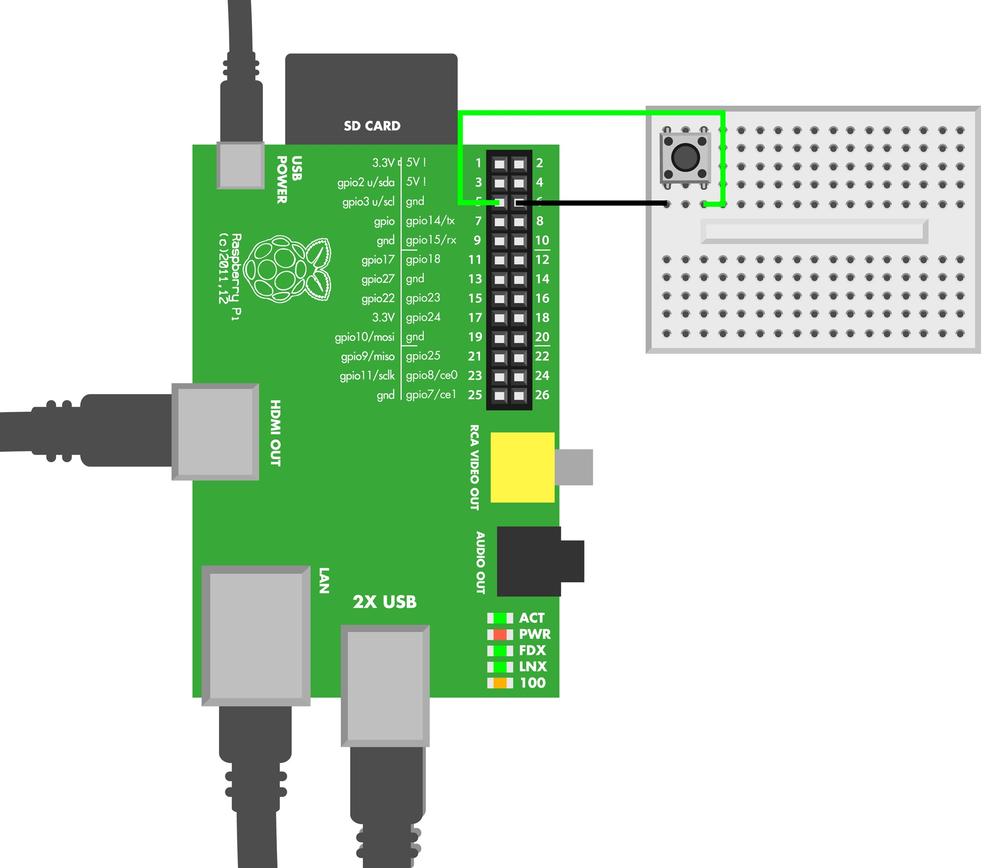
Experiment: Microswitch
A microswitch is a button (see Figure 5-5). When you press the button, the leads are connected. This experiment writes “0” to the serial port when the microswitch is pressed.
You can use a microswitch just like a regular button (see Experiment: Button). Just as with a button, the specific model of microswitch doesn’t matter, and you can use the same code and connection for any typical microswitch.

Microswitches are popular because of their low price, small size, and durability. A typical microswitch will last more than a million presses. The clicky sound and the feel of the click come from a tiny arm turning around a pivot.
This connection avoids floating pin by using a pull-up resistor (Pull-Up Resistor).
Microswitch Code and Connection for Arduino
Build the circuit shown in Figure 5-6 and upload the code shown in Example 5-3.

// microswitch.ino - print to serial if microswitch is down or up// (c) BotBook.com - Karvinen, Karvinen, ValtokariconstintswitchPin=2;intswitchState=-1;//voidsetup(){Serial.begin(115200);pinMode(switchPin,INPUT);digitalWrite(switchPin,HIGH);// internal pull-up //}voidloop(){switchState=digitalRead(switchPin);Serial.println(switchState);//delay(10);}
-
-
Writing HIGH to INPUT pin connects it to +5 V with a large (20 kilohm) resistor.
-
If button is pressed, the D2 pin is directly connected to ground through the button, and switchState is LOW. When D2 is directly connected to ground, the 20 kOhm pull-up resistor’s resistance is so large that the pull-up doesn’t affect the state of D2. If the button is not pressed, the internal pull-up resistor pulls it to HIGH (+5 V).
You can make simple feeler antennas for your robot from a microswitch just by hot gluing a zip tie to it (Figure 5-7).
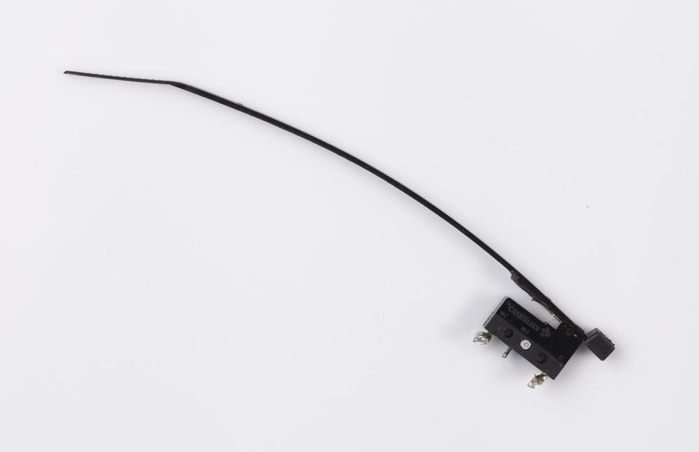
Microswitch Code and Connection for Raspberry Pi
Wire up the Raspberry Pi as shown in Figure 5-8 and run the Python program shown in Example 5-4.
# microswitch.py - write to screen if switch is pressed or not# (c) BotBook.com - Karvinen, Karvinen, Valtokariimporttimeimportbotbook_gpioasgpio#defmain():switchpin=3# has internal pull-up #gpio.mode(switchpin,"in")while(True):switchState=gpio.read(switchpin)#if(switchState==gpio.LOW):"Switch is pressed"else:"Switch is up"time.sleep(0.3)# secondsif__name__=="__main__":main()
-
Make sure there’s a copy of the botbook_gpio.py library in the same directory as this program. You can download this library along with all the example code from http://botbook.com. See GPIO Without Root for information on configuring your Raspberry Pi for GPIO access.
-
gpio2 and gpio3 pins have always-on internal pull-up resistors.
-
When the button is pressed down, gpio3 is connected to ground and thus LOW. The internal pull-up resistor’s resistance is so large that the pull-up resistor doesn’t affect gpio3 state when gpio3 is directly connected to ground. When the button is up, the pull-up resistor pulls it HIGH.
Experiment: Potentiometer (Variable Resistor, Pot)
In this experiment, you’ll control how quickly an LED blinks by turning a potentiometer.
A potentiometer is a variable resistor. You turn its knob to change its resistance.
A normal, non-variable resistor has just two leads. If you want to use a potentiometer in place of a single resistor, use the middle lead and either of the side leads.
Why does a potentiometer (or pot) have three leads, then? When you read a data pin, the pin must always be connected somewhere.
The easiest way to use a pot is to connect one side to positive (+5 V) and another side to ground (GND). Then the middle lead of the pot is connected to data pin. The voltage of the pot’s middle lead then changes between +5 V and GND as you turn it. This makes the pot a voltage divider, which is a circuit that lowers a voltage by dividing it between two resistors (one connected to positive voltage, the other to ground). In the case of a pot, the resistances on either side of the pot’s wiper change as you turn the knob.
You can see a diagram of a potentiometer in Figure 5-9. The green middle lead is connected to a data pin that measures voltage. The side leads are connected to ground (black) and +5 V (red). There is an arc-shaped, round resistor (red-black) from positive to negative.

By turning the knob, you choose where the wiper touches the resistor somewhere on its arc. Positive is not short-circuited to ground, because there is always the long arc-shaped resistor between positive and ground.
If you turn the pot to the minimum, the green wiper is touching black ground (GND). The data pin connected to the wiper then reads 0 V. The entirety of the arc-shaped resistor separates the wiper from the positive terminal.
If you turn the pot to the maximum, the green wiper touches the red positive terminal (+5 V). The data pin connected to the wiper then reads +5 V.
As you turn the wiper on the arc-shaped resistor, you can select any voltage between 0 V and +5 V.
This example is using Arduino’s +5 V. A pot works the same way in Raspberry Pi, but there you must use +3.3 V or you will damage your data pin.
Potentiometer Code and Connection for Arduino
Figure 5-10 shows the connection diagram for Arduino. Set up your circuit as shown, and then upload and run the sketch shown in Example 5-5.
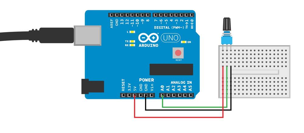
// pot.ino - control LED blinking speed with potentiometer// (c) BotBook.com - Karvinen, Karvinen, ValtokariintpotPin=A0;//intledPin=13;intx=0;// 0..1023voidsetup(){pinMode(ledPin,OUTPUT);pinMode(potPin,INPUT);}voidloop(){x=analogRead(potPin);//digitalWrite(ledPin,HIGH);delay(x/10);// ms //digitalWrite(ledPin,LOW);delay(x/10);}
-
You must use analog pins to read analog resistance sensors.
-
Now x has a raw analogRead() value, from 0 (0 V) to 1023 (5 V).
-
Potentiometer resistance controls the blinking delay. The delay varies from 0 ms to about 100 ms (1023/10).
Potentiometer Code and Connection for Raspberry Pi
Figure 5-11 shows the circuit diagram for using a pot with Raspberry Pi. Wire it up as shown, and run the program shown in Example 5-6.

Unlike Arduino, Raspberry Pi doesn’t have a built-in analog-to-digital converter. This means that all circuits using analog resistance sensors are more complicated with Raspberry Pi than with Arduino.
A potentiometer is a very simple component, as you can see by looking at the Arduino code for it. It’s taking that analog reading that’s a bit harder for Raspberry Pi.
In an earlier chapter, you took the easy way and read analog values with our botbook_mcp3002 library (Compound Eye Code and Connections for Raspberry Pi). But did it make you wonder how the botbook_mcp3002 library itself works?
This Raspberry Pi code introduces the underlying code needed to talk to the MCP3002 analog-to-digital converter. So instead of just having you use the library, this code shows you how to read values directly from that chip with the SPI interface, thus making it easier to understand how that library works (should you decide to delve into its inner workings).
Other code examples use the library, making them much simpler.
# pot.py - potentiometer with mcp3002# (c) BotBook.com - Karvinen, Karvinen, Valtokariimportspidev# installation help in book and botbook_mcp3002.py #importtimedefreadPotentiometer():spi=spidev.SpiDev()#spi.open(0,0)#command=[1,128,0]#reply=spi.xfer2(command)##Parse reply 10 bits from 24 bit packagedata=reply[1]&31#data=data<<6#data=data+(reply[2]>>2)#spi.close()#returndatadefmain():whileTrue:potentiometer=readPotentiometer()#("Current potentiometer value is%i"%potentiometer)time.sleep(0.5)if__name__=="__main__":main()
-
The spidev library makes it much easier to use SPI.
-
Create a new
SpiDevobject and store it to the variablespi.-
Open the first channel of the first connected device.
-
The first channel is 128; the second is 128+64.
-
Transfer one byte and read the reply.
-
Now you have to parse the reply, and find the interesting 10 bits out of 24 bits. We learned the format of the reply from the MCP3002 data sheet: take the second byte (1) from the reply, and perform a bitwise AND with 31 (which in binary is 00011111, which can also be written as
0b 0001 1111). After the operation, thedatavariable contains the five rightmost bits of reply[1]. If you want to understand bitwise operations in detail, see Bitwise Operations.
Shift
datasix bits left. For example,0b 0001 1001becomes0b 0110 0100 0000(we added spaces between digits to make it easier to read the long binary number). Now the rightmost six bits are zeroes.
Fill the six rightmost bits with the third byte of
data,data[2].
Release the SPI bus.

The main program doesn’t care about the implementation details we just described. Here, the main program’s life is made simple with a call to
readPotentiometer().
Look demanding? The rest of the code in this book uses the botbook_mcp3002 library, so you can concentrate on the bigger picture and let the library deal with all the bitwise operations.
Experiment: Sense Touch Without Touch (Capacitive Touch Sensor QT113)
The secret of a capacitive touch sensor is that it doesn’t sense touch at all. Instead, it measures how long it takes to load a piece of wire electrically. If there is a human (a big sack of water) nearby, it takes longer to load the wire.

The QT113 is an IC (integrated chip) for capacitive sensing. The protocol is simple: when a touch is detected, the output pin goes LOW.
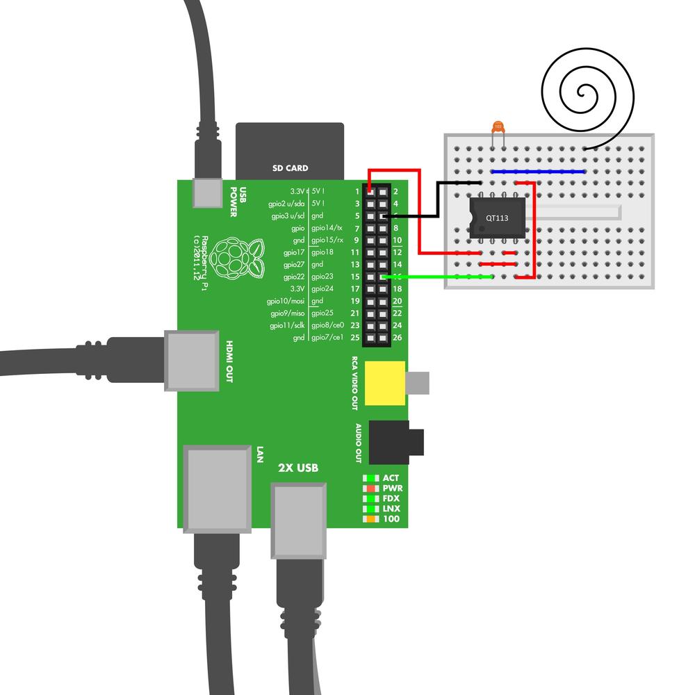
A good capacitive sensor needs some kind of surface. In this experiment, you’ll use a piece of metal wire turned into a spiral. A piece of aluminum foil could also work. The circuit also uses a 10-500 nF capacitor.
There are many ways to do capacitive sensing:
- A piece of wire and a simple timer
- A piece of wire and CapSense library
- A specialized chip (like QT113)
You may use a capacitive sensor every day; if you have a smartphone, its touchscreen is probably capacitive.
Ground your sensor. This kind of capacitive sensing requires a real ground, and a battery is not enough. For example, using an Arduino powered by a laptop doesn’t work reliably, until you connect your laptop to main power.
QT113 Code and Connection for Arduino
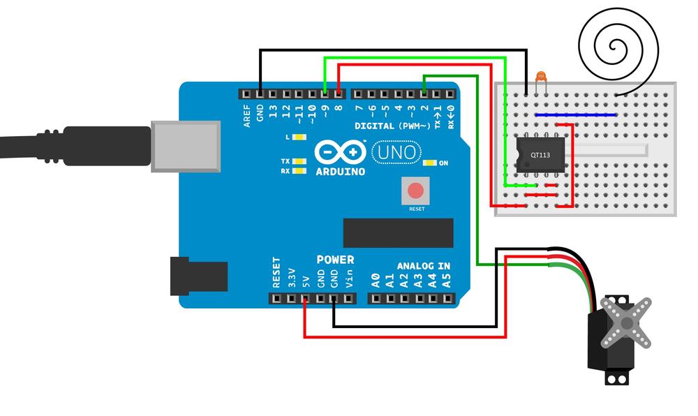
Figure 5-13 shows the circuit for using the QT113 with Arduino. Hook it up as shown, and then run the sketch shown in Example 5-7.

// qt113.ino - qt113 touch sensor// (c) BotBook.com - Karvinen, Karvinen, ValtokariintsensorPin=9;voidsetup(){pinMode(sensorPin,INPUT);Serial.begin(115200);}voidloop(){inttouch=digitalRead(sensorPin);//if(touch==LOW){Serial.println("Touch detected");}else{Serial.println("No Touch detected");}delay(100);}
-
It’s a simple digital switch sensor.
QT113 Code and Connection for Raspberry Pi
Figure 5-14 shows the connections for using Raspberry Pi with the QT113. Wire it up and run the program shown in Example 5-8.
# qt113.py - read touch information from QT113# (c) BotBook.com - Karvinen, Karvinen, Valtokariimporttimeimportbotbook_gpioasgpiodefmain():limitPin=23gpio.setMode(limitPin,"in")whileTrue:ifgpio.read(limitPin)==gpio.LOW:#("Touch detected!")time.sleep(0.5)if__name__=="__main__":main()
-
It’s a simple digital switch sensor.
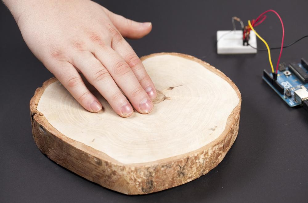
Environment Experiment: Sensing Touch Through Wood
When properly adjusted, a capacitive touch sensor can detect a hand through solid objects. The result is very convincing, as it feels as though the object is the sensor (Figure 5-15). For example, we made a bookshelf that changed the color of RGB LED lights when touched.
In reality, the wood does not affect capacitive sensing. The sensor behind the wood works through wood almost as well as it does through air.
To try this out, use the code and the connection for QT113 as you learned earlier. This time you’ll need to modify the touch wire to amplify its capability to detect changes in the electromagnetic field. Basically, you need a bigger chunk of metal on the other end the wire. Making a spiral or attaching some aluminum foil has worked well for us (Figure 5-16).

Experiment: Feel the Pressure (FlexiForce)
The FlexiForce sensors measures squeeze (pressure) on its round head (Figure 5-17).
FlexiForce is a simple analog resistance sensor. The more you squeeze, the lower the resistance. It has just two leads. The third lead in the middle is not connected, but is there just to make connecting it easier. As it’s just a resistor, it has no polarity, and it doesn’t matter which way you connect it. You can even test it with a multimeter that’s on the resistance setting.
Our students have used FlexiForce for an alarm that silences only when you get out of bed, a squeezing strong man competition, and for measuring squeezing precision. If you need a larger area for stepping over, you can put a piece of wood over the FlexiForce.

FlexiForce Code and Connection for Arduino
FlexiForce is an analog resistance sensor. As Arduino has a built-in analog-to-digital converter, reading the value is a simple call to analogRead().
A 1 megaohm pull-up resistor is used to avoid a floating pin. For an explanation of pull-up resistors, see Pull-Up Resistor. Figure 5-18 shows the wiring diagram, and Example 5-9 shows the sketch. After you wire up the Arduino, load the sketch and run it.

// flexiforce_25.ino - send flexiforce squeeze values to computer serial monitor// (c) BotBook.com - Karvinen, Karvinen, ValtokariintsqueezePin=A0;//intx=-1;// 0..1023voidsetup(){pinMode(squeezePin,INPUT);Serial.begin(115200);// bit/s}voidloop(){x=analogRead(squeezePin);//Serial.println(x);delay(500);// ms}
-
Arduino’s predefined constants (
A0,A1,A2…) are the best way to refer to analog pins in Arduino.-
As with any analog resistance sensor,
analogRead()returns the voltage of the pin, from 0 (0 V) to 1023 (+5 V).
FlexiForce Code and Connection for Raspberry Pi
The Raspberry Pi connection is similar to other analog resistance sensors (Figure 5-19). Because Raspberry Pi doesn’t have a built-in analog-to-digital converter, we use an external MCP3002 chip. Because the FlexiForce has just two leads, we use a pull-up resistor to avoid having a floating pin.
As the implementation details of MCP3002 analog converter are handled in the botbook_mcp3002 library, the main program itself is quite simple. Wire up the Raspberry Pi as shown in Figure 5-19, and then run the code shown in Example 5-10.

# flexiforce.py - sense force and print value to screen.# (c) BotBook.com - Karvinen, Karvinen, Valtokariimporttimeimportbotbook_mcp3002asmcp#defreadFlexiForce():returnmcp.readAnalog()#defmain():whileTrue:#f=readFlexiForce()#("Current force is%i"%f)#time.sleep(0.5)# s #if__name__=="__main__":main()
-
The botbook_mcp3002.py library file must be in the same directory as flexiforce.py. You must also install the spidev library, which is imported by botbook_mcp3002. See the comments in the beginning of botbook_mcp3002/botbook_mcp3002.py or Installing SpiDev.
-
Read the first sensor connected to MCP3002. The device and channel parameters are not needed when both are 0.
-
Embedded devices usually run as long as there is power. Use Control-C if you want to kill the program. When running a long or infinite loop, remember to add
delay()to the end of the loop.-
You can easily use
readFlexiForce()in bigger projects when it’s in a separate function like this. The function name explains what it does, so no comment is needed.-
Print the force. The string printed is formatted with a format string, where the value of
freplaces%i.-
Some delay is needed for the long loop (to avoid 100% CPU utilization) and also to allow the user to read the printed text.
Experiment: Build Your Own Touch Sensor
If capacitive sensing is just measuring the time it takes to load an electrical charge, could you build one yourself, and avoid using the QT113 chip? It’s possible to sense touch with just aluminum foil, a resistor, and good ground for your Arduino board.
Capacitive sensing is a practical matter. Even though the principle is simple, implementation is precise business. In addition to good grounding, the measurements must use sliding averages to smooth out any random fluctuation.
For reliable ground, the power source of Arduino must be connected to wall socket. If you are using a laptop, connect the laptop power cord into a wall socket. If you’re using a desktop, it’s of course always connected. You can also use a USB charger connected to wall socket.
The measuring part, aluminum foil, is connected between two data pins. Connecting something between data pins like this is quite rare—you usually connect one wire to ground or +5 V and the other to a data pin.
The code charges one data pin, and waits for however long it takes for the other data pin to reach the same charge (same voltage). As capacitance is the ability to hold charge, a big object like a human nearby will affect capacitance and result in a different charging time.
The smaller 10 kOhm resistor (brown-black-orange) helps protect against static electricity.
The big 1 MOhm to 50 MOhm resistor selects the sensitivity. The bigger the resistor, the farther away it detects a human. The trade-off for bigger detection distance is a slower reading speed.
Figure 5-20 shows the connection diagram for the Arduino, and Example 5-11 shows the sketch. Wire up the Arduino as shown, and then upload and run the code.

// diy_capacitive_sensor.ino - measure touch// (c) BotBook.com - Karvinen, Karvinen, ValtokariconstintsendPin=4;constintreadPin=6;voidsetup(){Serial.begin(115200);pinMode(sendPin,OUTPUT);pinMode(readPin,INPUT);digitalWrite(readPin,LOW);}voidloop(){inttime=0;digitalWrite(sendPin,HIGH);while(digitalRead(readPin)==LOW)time++;Serial.println(time);digitalWrite(sendPin,LOW);delay(100);}
Capsense Code and Connection for Raspberry Pi
Figure 5-21 shows the wiring diagram for Raspberry Pi. Wire it up as shown, and then run the code shown in Example 5-12.

# diy_capacity_sensor_simple.py - read touch from diy capacity sensor.# (c) BotBook.com - Karvinen, Karvinen, Valtokariimporttimeimportbotbook_gpioasgpiodefsample(count):sendPin=23recievePin=24gpio.mode(sendPin,"out")gpio.mode(recievePin,"in")gpio.write(sendPin,0)total=0# set lowforxinxrange(1,count):time.sleep(0.01)gpio.write(sendPin,gpio.HIGH)while(gpio.read(recievePin)==False):total+=1gpio.write(sendPin,gpio.LOW)returntotaldefmain():whileTrue:touch=sample(30)("Touch:%d"%touch)time.sleep(0.5)if__name__=="__main__":main()
Test Project: Haunted Ringing Bell
You enter a silent-looking reception desk. There is nobody in sight to check you in. You reach for the bell on the desk (Figure 5-22), but before you touch it… it rings!
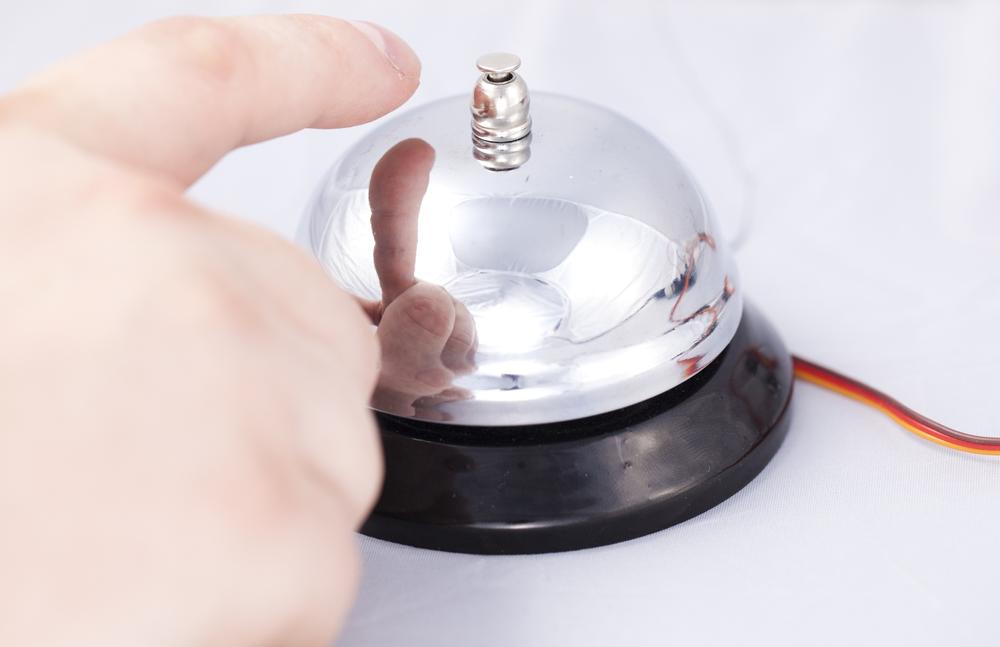
In this project we combine a capacitive touch sensor with an old-school ringing bell. The result is a bell that makes a sound just before you touch it. Even the bell knob moves by itself, giving this gadget a nice ghostly charm. You’ll also learn how to use a versatile new component, a servo motor.
What You’ll Learn
In the Haunted Ringing Bell project, you’ll learn how to:
- Build a gadget that reacts to your hand before you touch it.
- Make things move with servo motors.
- Control servo motors.
- Package a project to look like an innocent, everyday object.
Servo Motors

A servo is a motor you can precisely control (Figure 5-23). You can tell a standard servo to turn to a specific angle, such as 90 degrees. There are also full rotation servos where you control just the direction and rotation speed.
If you ever think you need a motor for your project, consider a servo first. The servo is in contrast to common DC motors, which are difficult to control and require extra components just for changing direction. Most moving things in Arduino and Raspberry Pi prototyping projects are done with servos.
A servo has three wires: black ground (0 V), red positive (+5 V), and control (yellow or white). Arduino sends a continuous stream of pulses to control wire. The length of these pulses tell the servo which angle to move to. The servo turns to this angle and then maintains it as long as pulses keep coming from Arduino.
The square wave (the pulse) is easy to create by rapidly changing a digital output pin between LOW and HIGH. To control the servo, Arduino must send 50 pulses a second, in other words, at the rate of 50 Hz.
50/s = 50 * 1/s = 50 * Hz = 50 Hz
The pulses are about 1 ms to 2 ms long. The longer the pulse, the bigger the angle. The pulse length between minimum and maximum angle centers the servo. Often, the center is about 1.5 ms.
For most servos, it’s not easy to find data sheets. But the update frequency (pulses per second) is usually the same, and it does not have to be exact.
The actual pulse length varies between servos, but it’s easy to find it out experimentally. To get an idea of pulse length versus angle, see the example values in Table 5-1.
| Pulse length ms | Pulse length µs | Angle | Comment |
0.5 ms | 500 µs | < -90 deg | Trying to turn over range, ugly sound from gears |
1 ms | 1000 µs | -90 deg | Extreme left |
1.5 ms | 1500 µs | 0% | Centered |
2 ms | 2000 µs | 90% | Extreme right |
2.5 ms | 2500 µs | > 90 deg | Over range, ugly sound |
Finding Servo Range
Even though you already know that servos use pulses from 1 ms to 2 ms, how does this help with the specific servo you have? You can find out the servo range experimentally. This code is essentially the “Hello World” for servos.
We always test a servo’s range when we buy new servos. Theoretically, the pulse length information should be available on the manufacturer’s website somewhere. In practice, many servos don’t have data sheets, or the correct data sheet is not easy to find.
We test every sensible pulse length from too small to too large (Example 5-13). As the code prints the pulse length to screen, we notice the key points and write them down (Table 5-2). The wiring diagram is shown in Figure 5-24.
Run the program. Open the serial monitor on Arduino IDE to see the pulse lengths printed (Tools→Serial Monitor). Set the serial monitor to the same speed (“baud”, bit/s) that the code uses.
| Pulse length µs | Angle | Comment |
-90 deg | Extreme left (test with code) | |
0 deg | Middle, mean of extreme left and right | |
+90 deg | Extreme right test with code) |
First, the pulse is way too short; it’s asking the servo to turn past its range. The servo doesn’t turn, but it might shake a bit and the gears could make a tiny but ugly noise. A short burst of this ugly noise is not harmful to the servo. When the servo starts turning, notice the point on the serial monitor. This is the -90 deg pulse length for extreme left.
When the servo stops turning, notice the pulse length. This is the pulse length for +90 degrees, extreme right.
The pulse length for the middle is the mean of maximum left and right. For example, if the extremes are 1 ms and 2 ms, the middle is 1.5 ms.
Some servos have a built-in potentiometer to set the center. If you have a servo like this, you can send the pulse for middle and experiment with the pot.
// servo_range.ino - turn servo and print values to serial// (c) BotBook.com - Karvinen, Karvinen, ValtokariintservoPin=2;voidpulseServo(intservoPin,intpulseLenUs)//{digitalWrite(servoPin,HIGH);//delayMicroseconds(pulseLenUs);//digitalWrite(servoPin,LOW);//delay(15);//}voidsetup(){pinMode(servoPin,OUTPUT);Serial.begin(115200);}voidloop(){for(inti=500;i<=3000;i=i+2){//pulseServo(servoPin,i);//Serial.println(i);}}
-
To send one short pulse, call
pulseServo(). The function is not run here where it’s defined, only when it’s called later. As the servo pin is given as a parameter, multiple calls to this function can control multiple servos.-
The pin is expected to be LOW first, meaning no pulse is being sent. Then you turn it HIGH, and the pulse starts.
-
Wait for a very short time. As the variable name implies, the unit is microseconds (µs), millionths of a second. Typical values are in Table 5-1. The purpose of this sketch is to find the exact values for your servo.
-
Turn the pin LOW, ending the pulse.
-
Wait for a while. The 15 ms time is short for humans but about 10 times longer than the length of the pulse. The pulses must be sent at least 50 times a second, so a pulse must be sent every 1/50 s = 0.02 s = 20 ms. We chose to wait a bit less than that.
-
Run the loop body with increasing pulse lengths. Start from the way-too-small 500 µs (0.5 ms), and end up at the way-too-high 3000 µs (3 ms). If you’ve forgotten how
forloops work, see .-
Send a short pulse to the servo. As a delay is included in
pulseServo(), you don’t need to wait in the main loop.

It’s also possible to control servos with the built-in Arduino library, Servo.h. Servo.h comes with the Arduino IDE and provides an object-oriented interface to servos. It lets you control the servos by specifying degrees, like myservo.write(180). You could find it handy when you need to control many standard servos. However, using the Arduino Servo library disables the use of analogWrite() on pins 9 and 10, and we prefer to keep that functionality enabled, so we don’t use the library. See http://arduino.cc/en/reference/servo for more information.
Haunted Bell Code and Connection for Arduino
Connect the servo motor and capacitive touch sensor as in the earlier examples (see Figure 5-25). Again you’ll need to use an 10-500 nF capacitor with QT113. The best value for us was 300 nF.
// haunted_bell.ino - bell rings just before you touch it// (c) BotBook.com - Karvinen, Karvinen, ValtokariintservoPin=2;intsensorPin=9;intsensorPowerPin=8;inthasRang=0;//voidpulseServo(intservoPin,intpulseLenUs)//{digitalWrite(servoPin,HIGH);delayMicroseconds(pulseLenUs);digitalWrite(servoPin,LOW);delay(20);}voidcling()//{for(inti=0;i<=3;i++){//pulseServo(servoPin,2000);}for(inti=0;i<=100;i++){pulseServo(servoPin,1000);}}voidsetup(){pinMode(servoPin,OUTPUT);pinMode(sensorPowerPin,OUTPUT);digitalWrite(sensorPowerPin,HIGH);pinMode(sensorPin,INPUT);}voidloop(){inttouch=digitalRead(sensorPin);//if(touch==HIGH){//hasRang=0;}if(touch==LOW&&hasRang==0){//cling();//hasRang=1;//digitalWrite(sensorPowerPin,LOW);delay(1);digitalWrite(sensorPowerPin,HIGH);}delay(100);}
-
The variable
hasRangwill be 1 if the bell has rung without the touch being removed. This will help make sure the bell rings only once. (We used integer 1 for true and 0 for false to avoid introducing a lot of Boolean logic, but feel free to use Bool in your programs if you prefer.)-
Servo control is explained in Example 5-13.
-
A function to ring the bell once. It’s in a separate function to make main
loop()easier to read, and because it’s one simple thing to do.-
To give the servo some time to move and hit the bell, you must send multiple pulses. As one
pulseServo()takes about 20 ms, 100 iterations is 2 seconds. So onering()runs about two seconds.-
SensorPinis LOW when there is touch.-
If there is no touch (HIGH), reset
hasRang. Now the bell will ring again if a hand comes near.-
If a hand is near and (
&&) it has not rung for this touch yet…-
…ring the bell once.
-
Remember that the bell has rung, to avoid ringing twice for the same near-touch.
Attaching Servo to Ringing Bell
Use hot glue to attach the servo inside the ringing bell (Figure 5-26). Before gluing, make sure that the servo arm pushes the moving part inside the bell so that it gives a solid sound. Servo movement should also allow the bell button to move naturally. It might take a few tries to get the servo attached exactly the right way. Now your haunted ringing bell is ready to spook unsuspecting victims.

You have now seen many kinds of touch and near-touch. You’ve played with buttons, microswitches, touch switches, and even used touch sensors without touch. After you’ve let the bell haunt your friends for a while, you can start applying this knowledge to your own projects. Think of any electronic devices around you: most sense touch in one way or another.