Chapter 5
Electromagnetic Fields and Waves
EM waves can neither be seen nor sensed nor are they audible.
The main aim of this chapter is to provide overall concepts of EM waves and their characteristics. They include:
- applications of EM waves
- wave equations and solutions
- propagation characteristics
- waves in conductors and dielectrics
- polarisation
- normal and oblique incidence of EM waves
- reflection and transmission coefficients
- Brewster angle and total internal reflection
- Surface impedance and Poynting theorem
- solved problems, points/formulae to remember, objective and multiple choice questions and exercise problems.
5.1 INTRODUCTION
A wave means a recurring function of time at a point.
Definition of wave It is defined as a physical phenomenon. In its reoccurrence, there is a time delay which is proportional to the space separation between two adjacent locations.
In general, wave is a carrier of energy or information and is a function of time as well as space.
As far as we are concerned, a wave means Electromagnetic wave (or simply EM wave). Maxwell predicted the existence of EM waves and established it through his well-known Maxwell’s equations. The same EM waves were investigated by Heinrich Hertz. Hertz conducted several experiments which could generate and detect EM waves. These radio waves are called Hertzian waves.
Examples radio, radar beams and TV signals.
5.2 APPLICATIONS OF EM WAVES
They have a wide range of applications in all types of communications like police radio, television, satellite, ionospheric, tropospheric, wireless, cellular, mobile communications and so on and in all types of radars like Doppler radar, MTI radar, speed trap radar, airport surveillance radar, weather forecasting radar, remote sensing radar, ground mapping radar, IFF radar, astronomy radar, fire control radar and so on. EM waves are also used in radiation therapy, microwave ovens and others.
Advantage in using EM waves for communication purposes is that the medium between the transmitter and receiver requires no maintenance. This is because free space is the best medium for EM wave propagation.
5.3 WAVE EQUATIONS IN FREE SPACE
Wave equations in free space are given by
|
|
|
Proof Free space is characterised by ∈r = 1, μr = 1 or ∈ = ∈O, μ = μ0, and σ = 0, ρv 0 and J = 0. Due to these characteristics of free space, Maxwell’s second equation becomes,
∇ × E = −Ḃ
= −μ0 Ḣ
[as B = μ0 H]
Taking curl on both sides, we get
Using standard vector identity, LHS is given by
and for the first Maxwell’s equation, RHS is
−μ0 ∇× Ḣ = −μ0![]() = −μ0 ∇0 Ë
= −μ0 ∇0 Ë
∇∇.E − ∇2 E = −μ0 ∈0 Ë
But ∇.D = ∇.∈0 E = ∈0 ∇.E = 0
Hence proved.
Now consider the first Maxwell’s equation
Taking curl on both sides
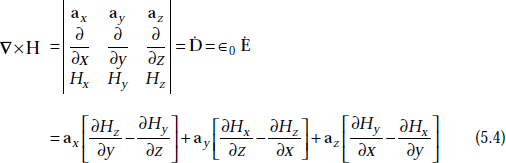
∇ × ∇ × H = ∈0 ∇ × Ė
∇∇.H − ∇2 H = ∈0 (−![]() ) = −μ0 ∈0 Ḧ
) = −μ0 ∈0 Ḧ
∇2 H = μ0 ∈0 Ḧ
[as ∇.H = 0]
Hence proved.
5.4 WAVE EQUATIONS FOR A CONDUCTING MEDIUM
Wave equations for a conducting medium (ρv = 0, σ ≠ 0 J ≠ 0) are given by
|
∇2 E = μ ∈ Ë + μσĖ |
and |
∇2 H = μ ∈ Ḧ + μσḢ |
Proof Consider the second Maxwell’s equation
Take curl on both sides
[as ∇.E = 0]
Hence proved.
Similarly, consider the first Maxwell’s equation
Take curl on both sides
[as ∇.H = 0]
Hence proved.
5.5 UNIFORM PLANE WAVE EQUATION
Definition of uniform plane wave An EM wave propagating in x-direction is said to be a uniform plane wave if its fields E and H are independent of y and z-directions.
It is defined as a wave whose electric and magnetic fields have constant amplitude over the equiphase surfaces. These waves exist only in free space at an infinite distance from the source.
A uniform plane wave propagating in x-direction has no x-components of E and H, that is, Ex = 0, Hx = 0.
The electric and magnetic fields of an EM wave are always perpendicular to each other. A typical wave is shown in Fig. 5.1.
Ex = 0 and Hx = 0 for a uniform plane wave
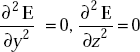
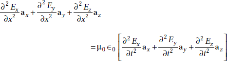
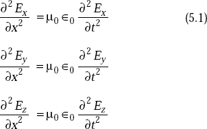
Proof The plane wave equation in free space is given by
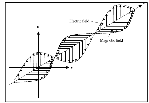
Fig. 5.1 Electromagnetic wave
thata is,
As per the definition of uniform plane wave,
|
E ≠ f (y) |
and |
E ≠ f (z) |
Hence the wave equation becomes
that is,
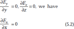
Equating the respective components on both sides, we get
Also we have
|
∇.D = 0 |
[as ρv = 0] |
or |
∇.∈0 E = 0 |
|
that is, |
∇.E = 0 |
|
So, ![]()
As
Substituting Equation (5.2) in (5.1), we get

This means that Ex should have one of the following solutions.
- Ex = 0
- Ex = a constant with time
- Ex increases uniformly with time, that is, Ex = Kt where K is constant.
If Ex = a constant and Ex = Kt, it will not be a part of wave motion. Therefore,
Similarly,
This means that the components of electric and magnetic fields of a uniform plane wave in the direction of propagation are zero.
5.6 GENERAL SOLUTION OF UNIFORM PLANE WAVE EQUATION
The wave equation in free space is
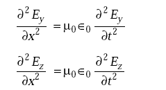
Applying the conditions of uniform plane wave equation, the above equation becomes
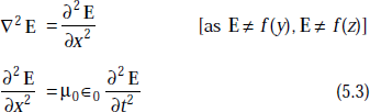
Equating the respective components on either side and as Ex = 0, we have
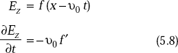
Equation (5.3) has a general solution given by
where f1 and f2 are functions of (x – v0t) and (x + v0t) respectively.
x is the direction of propagation of the wave.
f1(x – v0 t) represents a forward wave and
f2(x + v0 t) represents a reflected wave.
This reflected wave is present when there is a conductor which acts as a reflector. Otherwise, it is absent. As we are considering free space propagation, E will be f1(x – v0 t) only, that is,
This is the solution of uniform plane wave equation in free space.
The behaviour is represented typically in Fig. 5.2.
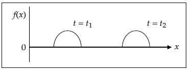
Fig. 5.2 A wave along x-direction
5.7 RELATION BETWEEN E AND H IN UNIFORM PLANE WAVE
The relation between E and H is
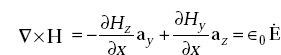
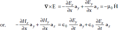
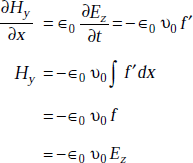
Proof First Maxwell’s equation is
But ![]()
Equation (5.4) becomes
Similarly,
and
Equating the respective components, we get
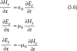
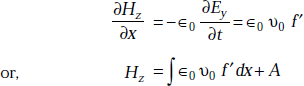
Writing Ey in the form of
that is,
where
From Equations (5.5) and (5.7), we have
As the constant, A cannot be a part of wave motion, we can put A = 0.
So, ![]()
As
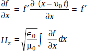
or, ![]()
or, 
Similarly, if we take
From Equations (5.6) and (5.8), we have
or,

Hence proved.
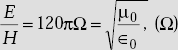
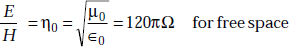
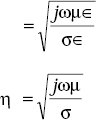
The intrinsic impedance or characteristic impedance, η0 is defined as
5.8 PROOF OF E AND H OF EM WAVE BEING PERPENDICULAR TO EACH OTHER
Consider
As
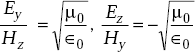
We get
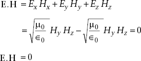
The dot product of two vectors E and H is zero only when the two vectors are perpendicular to each other. Hence proved.
5.9 WAVE EQUATIONS IN PHASOR FORM
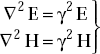
Wave equations in free space are
∇2 H = μ0 ∈0 Ḧ and
∇2 E = μ0 ∈0 Ë
If
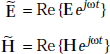
The wave equations become
These are wave equations in phasor form.
Note that a single time derivative of the field gives a factor of jω and a double time derivative of the field gives a factor of – ω2.
Similarly, the wave equations in conductive medium are
These can be represented in the following form
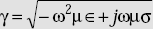
where = γ propagation constant ![]()
5.10 WAVE PROPAGATION IN LOSSLESS MEDIUM
The wave equation is
|
|
|
|
where |
|
The y-component of E may be written as
where A and B are arbitrary complex constants. Then
If A and B are real, it becomes
This is the sum of two waves. They travel in opposite directions. If A = B, the waves combine together and form a standing wave. Such waves do not progress.
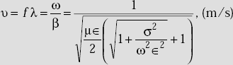
The wave velocity (v) It is defined as the velocity of propagation of the wave. It is also defined as
where |
ω = 2πf = angular frequency |
|
β = phase shift constant, radians/m |
Phase shift constant, β It is defined as a measure of the phase shift in radians per unit length.
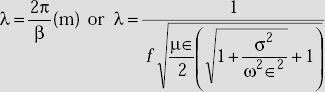
Wavelength of the wave, λ It is defined as that distance through which the sinusoidal wave passes through a full cycle of 2π radians,
that is, ![]()
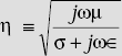
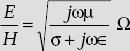
Phase velocity, (vp) It is defined as the velocity of some point in the sinusoidal waveform.
Intrinsic or characteristic impedance of a medium which has a finite value of conductivity is given by
5.11 PROPAGATION CHARACTERISTICS OF EM WAVES IN FREE SPACE
The wave equation in free space is
The propagation constant, γ(m–1)
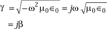
The phase constant, β(rad/m)
The propagation characteristics of EM wave in free space are:
Problem 5.1 If a wave with a frequency of 100 MHz propagates in free space, find the propagation constant.
Solution Propagation constant, γ in free space is
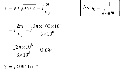
Problem 5.2 If H field is given by H(z, t) = 48cos(108t + 40z)ay, A/m, identify the amplitude, frequency and phase constant. Find the wavelength.
Solution Amplitude of the magnetic field
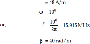
Now wavelength,
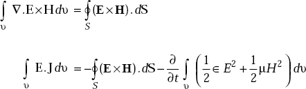
Problem 5.3 When the amplitude of the magnetic field in a plane wave is 2 A/m, (a) determine the magnitude of the electric field for the plane wave in free space (b) determine the magnitude of the electric field when the wave propagates in a medium which is characterised by σ = 0, μ = μ0 and ∈ = 4∈0.
Solution We have
-
But
- σ = 0, ∈r = 4, μr = 1
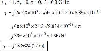
Problem 5.4 If ∈r = 9, μ = μ0, for the medium in which a wave with a frequency, f = 0.3 GHz is propagating, determine the propagation constant and intrinsic impedance of the medium when σ = o.
Solution The expression for propagation constant, γ is
As
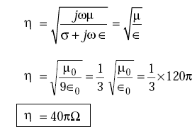
Intrinsic impedance,
Problem 5.5 The wavelength of an x-directed plane wave in a lossless medium is 0.25 m and the velocity of propagation is 1.5 × 1010 cm/s. The wave has z-directed electric field with an amplitude equal to 10 V/m. Find the frequency and permittivity of the medium. The medium has μ = μ0.
Solution v = 1.5 × 1010cm/sec = 1.5 × 10⁸m/s
Frequency of the wave,
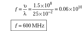
We have
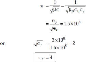
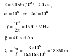
Problem 5.6 Identify frequency, phase constant when the electric field of an EM wave is given by E = 5.0 sin(108t – 4.0x) az. Also find λ.
Solution
5.12 PROPAGATION CHARACTERISTICS OF EM WAVES IN CONDUCTING MEDIUM
The wave equation in a conducting medium in phasor form is
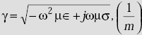
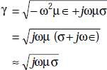
where the propagation constant, γ is
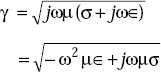
or, γ = α + jβ
where α is called the attenuation constant, dB/m
β is called phase constant, rad/m.
Phase constant, β is also called wave number and it is the imaginary part of propagation constant.
One solution of Equation (5.9) is
where x is the direction of propagation and in time varying form,
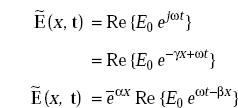
This is the equation of EM wave propagating in x-direction and attenuated by a factor e–αx
Attenuation constant, α (dB/m) It is defined as a constant which indicates the rate at which the wave amplitude reduces as it propagates from one point to another. It is the real part of propagation constant.
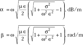
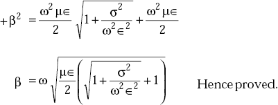
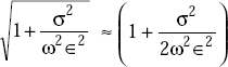
Expressions for α and β in a conducting medium
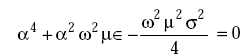
Proof From the wave equation, propagation constant, γ
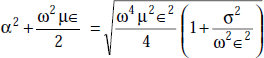
Squaring both sides, we get
Equating real and imaginary parts,
or, αβ = (ωμσ)/2
Thus,
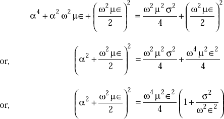
From Equations (5.10) and (5.11), we get
or,
or,
Dividing this by 4,
Adding and subtracting 
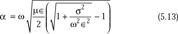
Taking square root on either side, we get
or,
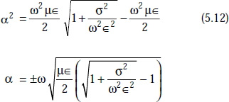
But α cannot be (–)ve. Hence
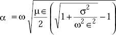
Hence proved.
Now substituting Equation (5.12) in Equation (5.10), we get
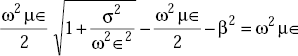
or,
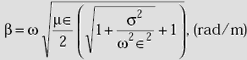
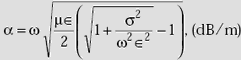
5.13 SUMMARY OF PROPAGATION CHARACTERISTICS OF EM WAVES IN A CONDUCTING MEDIUM
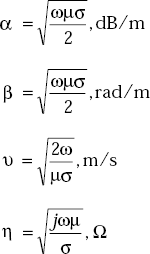
Propagation constant,
Phase shift constant,
Attenuation constant,
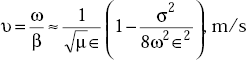
Velocity of propagation of EM wave,
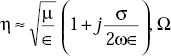
Intrinsic impedance, η
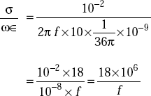
Problem 5.7 Earth has a conductivity of σ = 10–2 mho/m, ∈r = 10, μr = 2. What are the conducting characteristics of the earth at
- f = 50 Hz
- f = 1kHz
- f = 1MHz
- f = 100MHz
- f = 10GHz
Solution The parameters of earth are σ = 10–2 mho/m, ∈r = 10, μr = 2.
- At f = 50 Hz
So this is >>1. Hence it behaves like a good conductor.
- At f = 1 kHz,
This is >>1. Hence it behaves like a good conductor.
- At f = 1 MHz,
It behaves like a moderate conductor.
- At f = 100 MHz,
Earth behaves like a quasi-dielectric.
- At f = 10 GHz,
that is,

Earth behaves like a good dielectric.
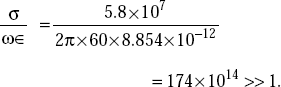
Problem 5.8 A medium like copper conductor which is characterised by the parameters σ = 5.8×10⁷ mho/m, ∈r = 1, μr = 1 supports a uniform plane wave of frequency 60 Hz. Find the attenuation constant, propagation constant, intrinsic impedance, wavelength and phase velocity of the wave.
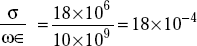
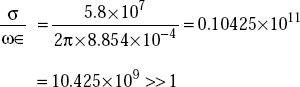
Solution Let us obtain the ratio
This is >>1. Therefore, it is a very good conductor.
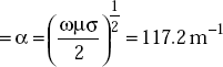
Attenuation constant
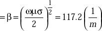
Phase constant
Propagation constant
Wavelength
Intrinsic impedance, η
Phase velocity of wave,
|
v = λ f = 0.0536×60=3.216m/s |
α = 117.2m−1 |
β = 117.2m−1 |
γ = 117.2 + j117.2m−1 |
λ = 5.36cm |
η = (2.022 + j2.022)μΩ |
v = 3.216m/s |
5.14 CONDUCTORS AND DIELECTRICS
As some media behave like good conductors at one frequency range and like good dielectrics at some other frequency range, the conventional definitions of conductors and dielectrics are not satisfactory in communication through EM waves.
The displacement current density,
and the conduction current density,

Definition of a good conductor
If ![]() , the medium is a good conductor.
, the medium is a good conductor.
Definition of a good dielectric
If ![]() , the medium is a good dielectric.
, the medium is a good dielectric.
Dissipation factor of a dielectric material (Df)is defined as
When Df is small for a specific type of dielectric material, the dissipation factor is practically the same as its power factor which is equal to sin ϕ. Here, ϕ = tan–1 Df.
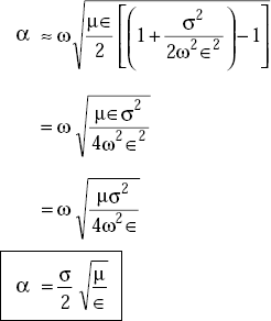
5.15 WAVE PROPAGATION CHARACTERISTICS IN GOOD DIELECTRICS
Attenuation constant, α is given by
For dielectrics, ![]()
Expanding  by Binomial series, higher order terms can be neglected.
Now Equation (5.13) becomes
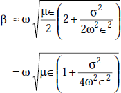
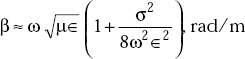
The phase shift constant, β is given by
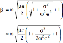
that is,
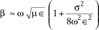
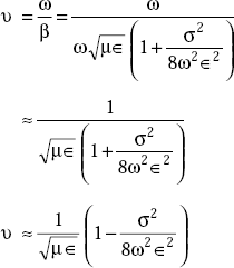
The velocity of propagation is
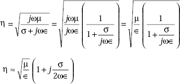
Intrinsic or characteristic impedance of general medium, η
5.16 SUMMARY OF THE PROPAGATION CHARACTERISTICS OF EM WAVES IN GOOD DIELECTRICS
5.17 WAVE PROPAGATION CHARACTERISTICS IN GOOD CONDUCTORS
The propagation constant, γ is given by
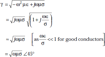
Thus, ![]()
or, ![]()
The velocity of the wave in a conductor is
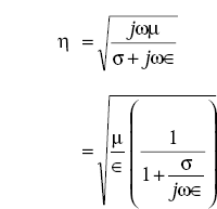
and the intrinsic impedance of the conductor is
5.18 SUMMARY OF CHARACTERISTICS OF WAVE PROPAGATION IN GOOD CONDUCTORS
5.19 DEPTH OF PENETRATION, δ (M)
Definition The depth of penetration is defined as that depth at which the wave attenuates to ![]() or approximately 37 per cent of its original amplitude. Depth of penetration is also called skin depth. It is a measure of depth to which an EM wave can penetrate the medium.
or approximately 37 per cent of its original amplitude. Depth of penetration is also called skin depth. It is a measure of depth to which an EM wave can penetrate the medium.
The depth of penetration
The conductivity of the medium attenuates the wave during propagation. At radio frequencies, the rate of attenuation is more in good conductors.
Proof of ![]()
Let the wave attenuation be represented by
z being the direction of propagation.
At z = τ
As per the definition of δ, we have
From Equations (5.14) and (5.15), we have
or,
Hence proved.
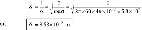
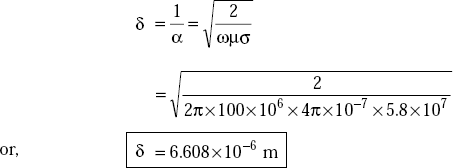
Problem 5.9 Find the depth of penetration, δ of an EM wave in copper at f = 60 Hz and f = 100 MHz. For copper, σ = 5.8 × 10⁷ mho/m, μr = 1, ∈r = 1.
Solution For copper, at f = 60 Hz,
Therefore, at f = 60 Hz, copper is a very good conductor.
The depth of penetration,
At f = 100 MHz,
Copper is a very good conductor at f = 100 MHz.
The depth of penetration,
5.20 POLARISATION OF A WAVE
Definition Polarisation of a wave is defined as the direction of the electric field at a given point as a function of time.
The polarisation of a composite wave is the direction of the electric field.
Types of Polarisations
These are of three types, namely
- Linear polarisation
- Circular polarisation
- Elliptical polarisation
Linear Polarisation
A wave is said to be linearly polarised if the electric field remains along a straight line as a function of time at some point in the medium. Linear polarisation of a wave is again of three types, namely
- Horizontal polarisation
- Vertical polarisation
- Theta polarisation
When a wave travels in z-direction with ![]() and
and ![]() fields lying in xy-plane, if
fields lying in xy-plane, if ![]() = 0 and
= 0 and ![]() is present, it is said to be x-polarised or horizontally polarised.
is present, it is said to be x-polarised or horizontally polarised.
If ![]() is only present and
is only present and ![]() = 0 the wave is said to be vertically (y-polarised) polarised. On the other hand, if
= 0 the wave is said to be vertically (y-polarised) polarised. On the other hand, if ![]() and
and ![]() are present and are in phase then the wave is said to be θ-polarised. This is given by
are present and are in phase then the wave is said to be θ-polarised. This is given by
Circular Polarisation
A wave is said to be circularly polarised when the electric field traces a circle. If ![]() and
and ![]() have equal magnitudes and a 90 degree phase difference, the locus of the resultant
have equal magnitudes and a 90 degree phase difference, the locus of the resultant ![]() is a circle and the wave is circularly polarised.
is a circle and the wave is circularly polarised.
Let E of a uniform plane wave travelling in the z-direction be represented by
and in time varying form
As the wave moves in z-direction, ![]() and
and ![]() lie in x-y plane.
lie in x-y plane.
Here, Ec is a complex vector, that is, Ec can be written as
where E1 and E2 are real vectors.
At some point in space (say z = 0) ![]() becomes
becomes
As per the definition of circular polarisation, the electric vector at z = 0 is expressed as
that is,
So,
This represents a circle.
Elliptical Polarisation
If ![]() and
and ![]() are not equal in magnitude and they differ by 90° phase, then the tip of the resultant electric vector traces an ellipse. The wave is said to be elliptically polarised.
are not equal in magnitude and they differ by 90° phase, then the tip of the resultant electric vector traces an ellipse. The wave is said to be elliptically polarised.
Here Ec can be written as
or,

This is the equation of an ellipse and hence the wave is said to be elliptically polarised.
5.21 SOURCES OF DIFFERENT POLARISED EM WAVES
Horizontal dipole produces horizontally polarised waves.
Vertical dipole produces vertically polarised waves.
Inclined dipole produces θ-polarised waves.
Circular slots produce circularly polarised waves.
Elliptical slots produce elliptically polarised waves.
5.22 DIRECTION COSINES OF A VECTOR FIELD
Definition The direction cosine of a vector field is defined as the cosine of the angle made by the vector with the required coordinate axis.
Consider a vector E which is arbitrarily oriented with respect to the Cartesian coordinate axes. Assume E makes angles θx, θy and θz with x, y and z-axes (Fig. 5.3). Then the component of a vector in a given direction is the projection of the vector, E on a line in that direction, that is,
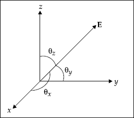
Fig. 5.3 Arbitrarily oriented vector, E
cos θx, cos θy and cos θz are known as direction cosines of the vector along the coordinate axes.
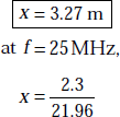
Problem 5.10 A vessel under sea water requires a minimum signal level of 20μ V/m. What is the depth in the sea that can be reached by a 4.0 MHz plane wave from an aeroplane? The wave has an electric field intensity of 100 V/m. The propagation is vertical into the sea. For sea water, σ = 4 mho/m, m μr = 1, ∈r = 81.
Solution At f = 4.0 MHz = 4.0 × 10⁶ Hz
For sea water
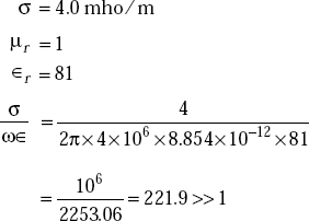
Hence sea water is a good conductor.
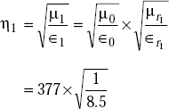
Intrinsic impedance of sea water,
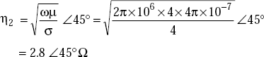
η1 (free space) = 377Ω
α1 (free space) = 0
β1 (free space) ![]()
Transmission coefficient
Transmission coefficient
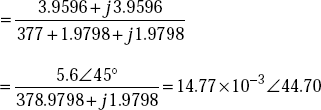
The transmitted electric field
Propagation takes place in the form of ![]() . Therefore, the distance at which the signal becomes 20μ V/m is found out from
. Therefore, the distance at which the signal becomes 20μ V/m is found out from
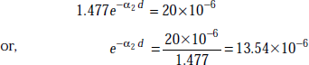
or,
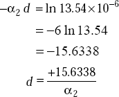
But
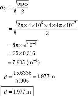
that is, the signal will reach the vessel when it is at a depth of 1.977 m.
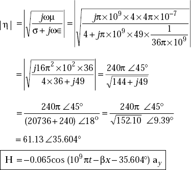
Problem 5.11 The electric field of a plane wave propagating in a medium is given by E = 4.0e–αx cos(109πt) – βx)az V/m. The medium is characterised by ∈r = 49, μr = 4 and σ = 4 mho/m. Find the magnetic field of the wave.
Solution Here ω = π×109
The ratio ![]()
This is neither << 1 nor >>
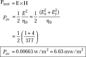
Problem 5.12 An elliptical polarised wave has an electric field of
Find the power per unit area conveyed by the wave in free space.
Solution |
Ex = sin(ωt − βz), V/m |
|
Ey = 2sin(ωt − βz + 75°), V/m |
According to Poynting theorem, we have
5.23 WAVES ON A PERFECT CONDUCTOR—NORMAL INCIDENCE
- When a wave in air is incident on a perfect conductor normally, it is entirely reflected.
- As neither E nor H can exist in a perfect conductor, none of the energy is transmitted through it.
- As there are no losses within a perfect conductor, no energy is absorbed in it.
- When an EM wave travelling in one medium is incident upon a second medium, it is partially reflected and partially transmitted.
Total fields of a wave at any point after reflection with normal incidence on a perfect conductor
Resultant electric field,
Ei is the amplitude of the electric field of the incident wave, z = direction of propagation.
Resultant magnetic field,
Hi is the amplitude of the magnetic field of the incident wave.
Let the electric field of the incident wave be
Then the electric field of the reflected wave is
The boundary condition is
This requires that
At z = 0
This means, the amplitudes of incident and reflected electric field strengths are equal but with a phase reversal on reflection.
Now
In time varying form
This obviously represents a standing wave. The variation of ER is shown in Fig. 5.4.
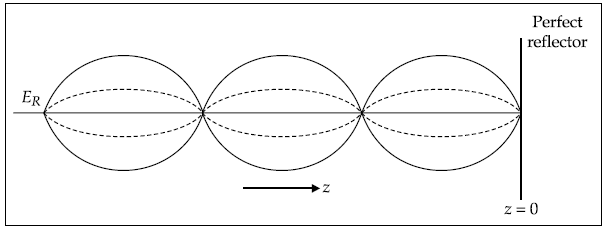
Fig. 5.4 Standing waves
Conclusions
- The magnitude of electric field varies sinusoidally with distance from the reflecting plane.
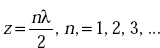
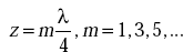
- ER = 0 at the surface of the conductor (z = 0) and also at
- (ER)max = 2Ei.
- ER is maximum at
Resultant magnetic field, HR
Let us write HR as HR(z) = Hie–jβz + Hrejβz
At the surface of a perfect conductor,
As Js is not specified, we cannot use this boundary condition. Suppose Hi = –Hr. It leads to identical directions of incident and reflected powers. This cannot be true. Therefore, Hi and Hr should be the same at z = 0,
In time varying form,
This also represents a standing wave. The variation of the HR is shown in Fig. 5.5.
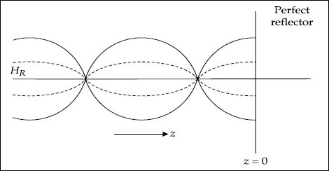
Fig. 5.5 Variation of resultant magnetic field
Conclusions
- Magnitude of HR varies cosinusoidally with distance.
- HR = 0 at
- (HR)max = 2Hi
- HR is maximum at
 from the surface.
5.24 WAVES ON DIELECTRIC—NORMAL INCIDENCE
When an EM wave is incident normally on the surface of a dielectric, reflection and transmission take place.
For a perfect dielectric, σ = 0. Hence, there is no loss or no absorption of energy in it.
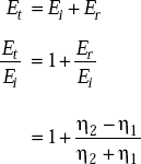
Reflection coefficient It is defined as the ratio of reflected wave and incident wave.
That is, the reflection coefficient
Reflection coefficient for
Reflection coefficient for
where
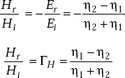
Transmission coefficient It is defined as the ratio of transmitted wave and incident wave.
Transmission coefficient
Transmission coefficient for E is

and transmission coefficient for H is

Expressions for reflection and transmission coefficients are:
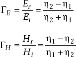
where η1 and η2 are intrinsic impedances of medium 1 and medium 2 respectively.
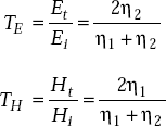
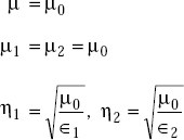
Proof Let ∈1, μ1, η1 be the permittivity, permeability and intrinsic impedance of medium 1. ∈2, μ2, η2 are the values for medium 2. We know that
At the boundary of a dielectric, the tangential components of E and H are continuous, that is,
From the above equations, we have
So,
Now consider,
So,
From the above equations
Hence proved.
Similarly, consider
5.25 OBLIQUE INCIDENCE OF A PLANE WAVE ON A BOUNDARY PLANE
Reflection and transmission of a wave depend on
- the type of polarisation of a wave
- the medium of the boundary.
General polarisations, namely, parallel and perpendicular, are considered.
Parallel Polarisation
It is defined as the polarisation in which the electric field of the wave is parallel to the plane of incidence. Parallel polarisation is also called vertical polarisation.
Perpendicular Polarisation
It is defined as the polarisation in which the electric field of the wave is perpendicular to the plane of incidence. Perpendicular polarisation is also called horizontal polarisation.
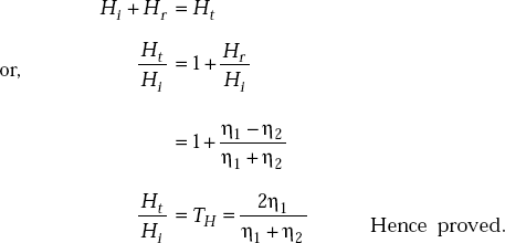
Plane of Incidence
It is a plane which contains the incident, reflected and transmitted rays and is normal to the boundary.
It is described in Fig. 5.6 in which x-y is the plane of incidence.
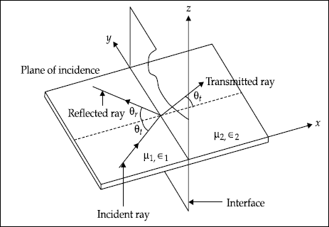
Fig. 5.6 Plane of incidence
5.26 OBLIQUE INCIDENCE OF WAVE ON PERFECT CONDUCTOR
When a wave is incident on a perfect conductor, it is reflected back into the same medium. The resultant fields depend on the type of polarisation.
Parallel Polarisation
The incident and reflected electric fields are shown in Fig. 5.7.
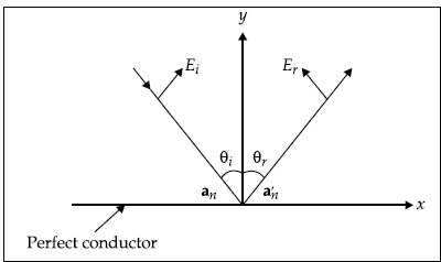
Fig. 5.7 Incident and reflected electric fields in parallel polarisation
The incident and reflected magnetic fields are shown in Fig. 5.8.
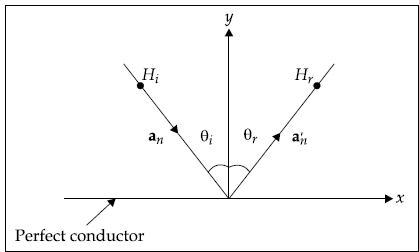
Fig. 5.8 Incident and reflected magnetic fields in parallel polarisation
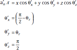
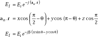
The incident magnetic field is given by
where
an = unit vector normal to the plane
r = (x, y, z) is a radius vector on the plane
an.r = x cos θx + y cos θy + z cos θz
where
θx, θy and θz are the angles made by a unit vector normal to the plane with x, y and z-axes (Fig. 5.9).
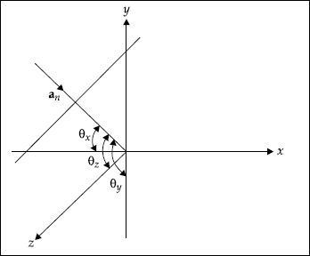
Fig. 5.9 Unit vector normal to the plane
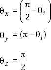
an . r = x sin θi − y cos θi
HI = Hi e−γ(xsinθ − ycosθ)
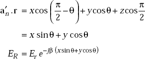
Similarly, ![]()
Here,
![]() are the angles made by the unit vector normal to the plane with x, y and z-axes (Fig. 5.10).
are the angles made by the unit vector normal to the plane with x, y and z-axes (Fig. 5.10).
HR = Hr e−γ (xsin θ + y cos θ)
HT = HI + HR
= Hi e−γ (xsin θ − y cos θ) + Hr e−γ (xsin θ + y cos θ)
At the surfaces of the conductor, Ei = –Er. In order to satisfy the direction of power flow, Hi must be equal to Hr that is, Hi = Hr . Now
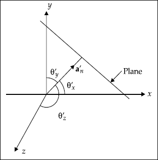
Fig. 5.10 Unit vector normal to the plane
Here, γ = propagation constant = α + jβ
But in free space, α = 0.
Hence γ = jβ
The expression for HT is given by
where, βy = β cosθ, βx = β sinθ
Conclusions
- The maximum value of HT is 2Hi.
- The maximum occurs at y = 0, at
 and at its even multiples.
 - The minimum is zero and it occurs at
 and at its odd multiples.
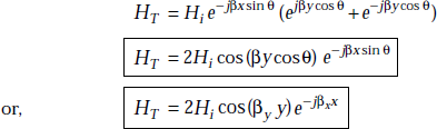
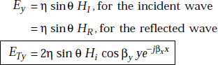
In order to find the resultant electric field, we can make use of the relations between the magnetic and electric fields.
EI = ηHI
Ex = η cosθ HI, for the incident wave
= −η cosq HR, for the reflected wave
Similarly,
Ey = η sin θ HI, for the incident wave
= η cos θ HR, for the reflected wave
The resultant Ex is
Similarly,
Perpendicular Polarisation
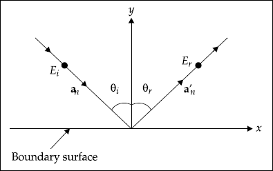
Fig. 5.11 Electric field in perpendicular polarisation
For the incident wave,
For the reflected wave,
But Ei = Er
ET = Ei [e−jβ (x sin β − y cos β) + e−jβ (x sin θ + y cos θ)]
= 2j Ei sin (βy cos θ) e−jβx sin θ
or, ![]()
where βy = β cosθ, βx = β sinθ
5.27 OBLIQUE INCIDENCE OF A PLANE WAVE ON DIELECTRIC
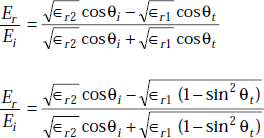
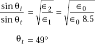
When a wave is incident on a dielectric, a part of it is reflected and a part of it is transmitted through the dielectric. If θi, θr and θt are the angles of the incident, reflected and transmitted rays, θi = θr. The angles θi and θt are related by Snell’s law, that is,
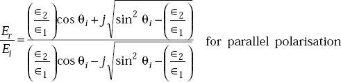
Parallel Polarisation
Consider Fig. 5.12.
The boundary condition on E is
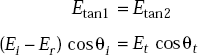
Dividing both sides by Ei, we get
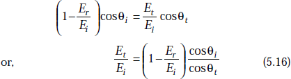
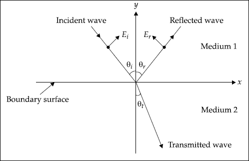
Fig. 5.12 Incident, reflected and transmitted rays
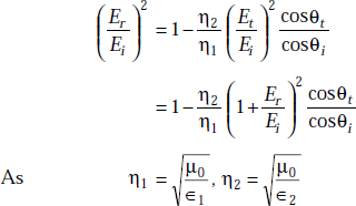
By the law of conservation of energy, incident energy is equal to the sum the of reflected and transmitted energies, that is,
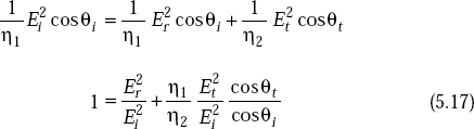
From Equations (5.16) and (5.17)
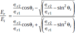
Simplifying this expression, we get
|
|
|
|
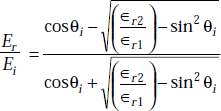
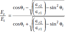
For most of the dielectrics,
Hence the reflection coefficient is
as
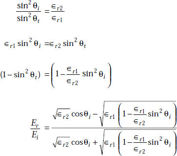
or,
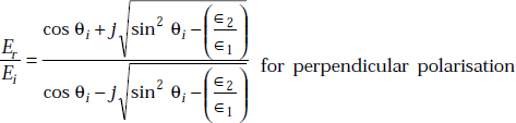
Perpendicular Polarisation
Consider Fig. 5.13 in which E is z-directed and x-y is the plane of incidence.
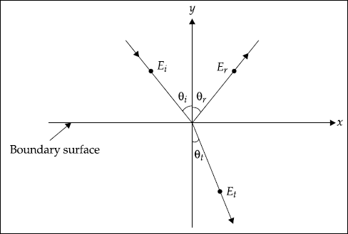
Fig. 5.13 Wave incidence with perpendicular polarisation
From the boundary condition, we have

From the law of conservation of energy, we have
On simplification of the above expression, we get
5.28 BREWSTER ANGLE
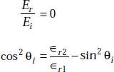
Definition Brewster angle is the angle of incidence at which there is no reflection.
Brewster angle for parallel polarisation
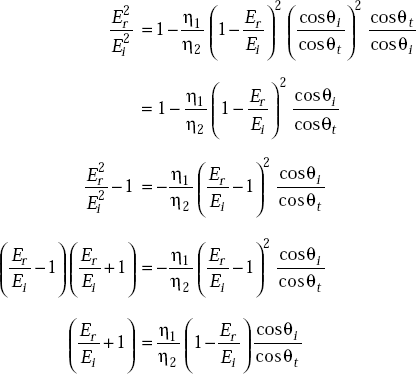
For parallel polarisation, we have
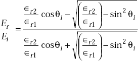
At Brewster angle, ![]()
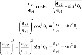
Simplifying this, we get
or,
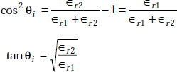
Brewster angle, ![]()
Brewster angle for perpendicular polarisation
We have
At Brewster angle,
or,

Hence, the condition for no reflection in perpendicular polarisation is ∈r1 = ∈r2.
5.29 TOTAL INTERNAL REFLECTION
Definition Total internal reflection is said to exist if
- the angle of incidence is very high
- medium 1 is denser than medium 2 and
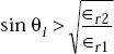
For total internal reflection,
The concept of total internal reflection is often used in binocular optics. For these applications, glass prisms are used to shorten the instrument.
5.30 SURFACE IMPEDANCE
Definition It is defined as the ratio of the tangential electric field, Et to the linear current density, Js which flows due to the electric field, that is,
For a flat thick conducting sheet, the current density (Fig. 5.14) is given by
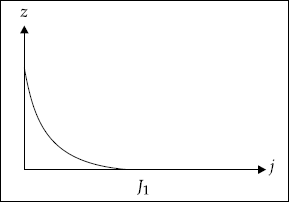
Fig. 5.14 Current density
As the conductor considered is thick, the depth of penetration is much smaller compared to the thickness of the conductor.
The surface current density is
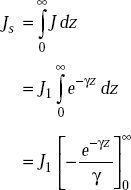
The current density at the surface, J1 is given by
From the above expressions, we have
For a perfect conductor, σ is very high.

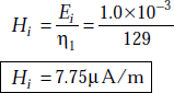
Problem 5.13 A perpendicularly polarised wave is incident at an angle of θi = 15°. It is propagating from medium 1 to medium 2. Medium 1 is defined by ∈r1 = 8.5, μr1 = 1, σ1 = 0 and medium 2 is free space. If Ei = 1.0 mV/m, determine Er, Hi, Hr.
Solution The intrinsic impedance of medium 1 is given by
As medium 2 is free space,
By Snell’s law
The reflection coefficient for electric field is
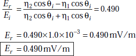
Now ![]()
or,
and similarly, ![]()
or, ![]()
5.31 POYNTING VECTOR AND FLOW OF POWER
When EM waves travel from one point to another, there will be energy flow across the surface involved.
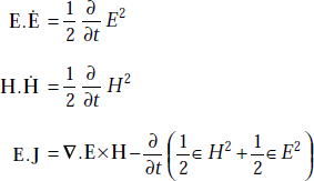
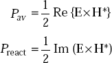
Poynting Theorem It states that the cross product of E and H at any point is a measure of the rate of energy flow per unit area at that point, that is,
Poynting Vector, P is defined as
If E and H are instantaneous, P is also instantaneous.
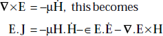
Proof First Maxwell’s equation is
or, J = ∇ × H − ∈ Ė
that is, E.J = E.∇ × H − ∈ E.Ë
But
∇.(E × H) = H.∇ × E − E.∇ × H
E.J = H.∇ × E − ∇.E × H − ∈ E.Ė
As
Here
Taking volume integral,
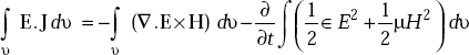
By divergence theorem,
The left hand side represents energy dissipated in the volume.
The second term on the right hand side represents the rate at which the stored energy in magnetic and electric fields is changing. (–)ve sign indicates decrease. Therefore, by the law of conservation of energy, the rate of energy dissipation in the volume is equal to the rate at which the stored energy in static electric and magnetic fields in the volume is decreasing plus the rate at which the energy is entering the volume from outside. Therefore,
represents inward power flow, or
represents outward power flow.
E × H represents power flow per unit area, or, E × H is in watts/m2.
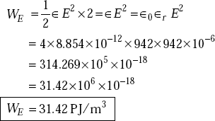
Problem 5.14 The magnetic field, H of a plane wave has a magnitude of 5 mA/m in a medium defined by ∈r = 4, μr = 1. Determine (a) the average power flow (b) the maximum energy density in the plane wave.
Solution (a) We have
(b) The maximum energy density of the wave is
Problem 5.15 A plane wave travelling in a medium of ∈r = 1, μr = 1 has an electric field intensity of ![]() . Determine the energy density in the magnetic field and also the total energy density.
. Determine the energy density in the magnetic field and also the total energy density.
Solution The electric energy density is given by
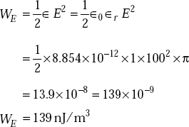
As the electric energy density is equal to that of the magnetic field for a plane travelling wave,
So the total energy density,
Problem 5.16 The conductivity of sea water, σ = 5 mho/m, ∈r = 80. What is the distance, an EM wave can be transmitted at 25 kHz and 25 MHz when the range corresponds to 90% of attenuation?
Solution If the wave is moving in x-direction, we have
that is,
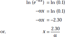
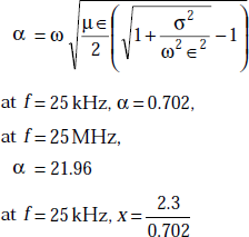
Hence
or ![]()
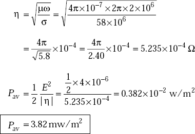
Problem 5.17 A plane wave with a frequency of 2 MHz is incident upon a copper conductor normally. The wave has an electric field amplitude of E = 2 mV/m. Copper has μr = 1, ∈r = 1 and σ = 5.8 × 10⁷ mho/m. Find the average power density absorbed by copper.
Solution Copper is a good conductor
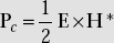
5.32 COMPLEX POYNTING VECTOR
It is defined as
where H* is the complex conjugate of H.
Complex Poynting vector is useful to find average power flow. We have,
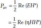
If
POINTS/FORMULAE TO REMEMBER
- For a uniform plane wave propagating in x-direction, Ex = 0 and Hx = 0.
- Intrinsic impedance of free space is 120πΩ.
- Intrinsic impedance of a medium is
 .
. - The wave equations in a conductive medium are:
∇2 E = μ ∈ Ë + μσĖ∇2 H = μ ∈ Ḧ + μσḢ
- The solution of uniform plane wave propagating in x-direction is
E = f (x–v0 t)
- Propagation constant is
- Attenuation constant in free space is zero.
- Phase constant in free space is

- Phase velocity in free space,

- Dissipation factor,

- Attenuation constant in good conductors is

- Phase constant in good conductors is

- α in good dielectrics is

- Depth of penetration,

- Poynting vector, P = E × H
- Complex Poynting vector,
- Reflection coefficient =
- Transmission coefficient =

- Brewster angle,
- Snell’s law is given by

OBJECTIVE QUESTIONS
1. Characteristic impedance of a medium is |
(Yes/No) |
2. Velocity of propagation of uniform plane wave and its phase velocity are identical. |
(Yes/No) |
3. Brewster angle is the angle of reflection. |
(Yes/No) |
4. P × H gives average power. |
(Yes/No) |
5. E = ej2x ay means that E = sin (ωt + 2x) ay. |
(Yes/No) |
6. E and H in good conductors are in time phase. |
(Yes/No) |
7. Power density is represented by Poynting vector. |
(Yes/No) |
8. Complex Poynting vector is E × H*. |
(Yes/No) |
9. The units of Poynting vector are watts. |
(Yes/No) |
10. Depth of penetration is nothing but α. |
(Yes/No) |
11. β has the unit of radian. |
(Yes/No) |
12. Unit of α and β are the same. |
(Yes/No) |
13. Unit of the propagation constant is m–1. |
(Yes/No) |
14. Brewster angle is the same as critical angle. |
(Yes/No) |
15. In circular polarisation, Ex and Ey components have the same magnitude. |
(Yes/No) |
16. In elliptical polarisation, Ex and Ey components have the same magnitude. |
(Yes/No) |
17. Horizontal polarisation is said to be linear polarisation. |
(Yes/No) |
18. When an EM wave is incident on a perfect conductor normally, standing waves are produced. |
(Yes/No) |
19. According to Snell’s law, the angle of incidence and the angle of reflection are the same. |
(Yes/No) |
20. Polarisation and the direction of propagation of an EM wave are one and the same. |
(Yes/No) |
21. In perpendicular polarisation with oblique incidence on a dielectric, there exists Brewster angle. |
(Yes/No) |
23. If the attenuation of a plane wave in a medium is 22.5 × 10³ m–1, the depth of penetration is _______. |
|
24. If the depth of penetration of a plane wave in a medium is 2 mm, the attenuation constant is _______. |
|
25. Brewster angle is given by _______. |
|
Answers
1. No |
2. Yes |
3. No |
4. No |
5. Yes |
6. No |
7. Yes |
8. No |
9. No |
10. No |
11. No |
12. No |
13. Yes |
14. No |
15. Yes |
16. No |
17. Yes |
18. Yes |
19. No |
20. No |
21. No |
22. 0.2 rad/m |
23. 4 cm |
|
|
25. |
||

MULTIPLE CHOICE QUESTIONS
- Poynting vector is given by
- E × H
- E. H
- H × E
- H. E
- Poynting vector gives
- rate of energy flow
- direction of polarisation
- electric field
- magnetic field
- E.H of a uniform plane wave is
- EH
- 0
- ηE2
- ηH2
- Absolute permeability of free space is
- 4π × 10–7 A/m
- 4π × 10–7 H/m
- 4π × 10–7 F/m
- 4π × 10–7 H/m2
- For a uniform plane wave in the x-direction
- Ex = 0
- Hx = 0
- Ex = 0 and Hx = 0
- Ez = 0
- Depth of penetration in free space is
- infinity
- 1/α
- 0
- small
- Complex Poynting vector, P is
- P = E × H*
- P = E × H*

- E × H
- Uniform plane wave is
- longitudinal in nature
- transverse in nature
- neither transverse nor longitudinal
- x-directed
- The direction of propagation of EM wave is obtained from
- E × H
- E.H
- E
- H
- The velocity of an EM wave is
- inversely proportional to β
- inversely proportional to α
- directly proportional to β
- directly proportional to α
- Velocity of the wave in an ideal conductor is
- zero
- very large
- moderate
- small
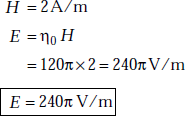
- If E = 2 V/m of a wave in free space, (H) is

- 60π A/m
- 120π A/m
- 240π A/m
- If wet soil has σ = 10–2 mho/m, ∈r = 15, μr = 1, f = 60 Hz, it is a
- good conductor
- good dielectric
- semi-conductor
- magnetic material
- If wet soil has σ = 10–2 mho/m, ∈r = 15, μr = 1, at 10 GHz, it is a
- good conductor
- good dielectric
- semi-conductor
- semi-dielectric
- The cosine of the angle between two vectors is
- sum of the products of the directions of the two vectors
- difference of the products of the directions of the two vectors
- product of the products of the directions of the two vectors
- zero
- If E is a vector, then ∇.∇ × E is
- 0
- 1
- does not exist
- none of these
- Velocity of an EM wave in free space is
- independent of f
- increases with increase in f
- decreases with increase in f
- zero
- The direction of propagation of an EM wave is given by
- the direction of E
- the direction of H
- the direction of E × H
- the direction of E.H
- For uniform plane wave propagating in z-direction
- Ex = 0
- Hx = 0
- Ey = 0, Hy = 0
- Ez = 0, Hz = 0
- For free space,
- σ = ∞
- σ = 0
- J ≠ 0
- μr = 0
- Velocity of propagation of an EM wave is
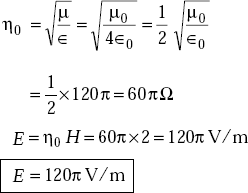
- The intrinsic impedance of the medium whose σ = 0, ∈r = 9, μr = 1 is
- 40πΩ
- 9Ω
- 120πΩ
- 60πΩ
- The wavelength of a wave with a propagation constant = 0.1π + j0.2π is
- 10 m
- 20 m
- 30 m
- 25 m
- Electric field just above a conductor is always
- normal to the surface
- tangential to source
- zero
- ∞
Answers
1. (a) |
2. (a) |
3. (b) |
4. (b) |
5. (c) |
6. (a) |
7. (c) |
8. (b) |
9. (a) |
10. (a) |
11. (a) |
12. (a) |
13. (a) |
14. (b) |
15. (a) |
16. (a) |
17. (a) |
18. (c) |
19. (d) |
20. (b) |
21. (c) |
22. (a) |
23. (a) |
24. (a) |
EXERCISE PROBLEMS
- Find the depth of penetration for copper at 20 MHz. For copper
σ = 5.8 × 10⁷ mho/m, μr = 1
- What is the velocity of propagation of a uniform plane wave in a medium whose ∈r = 10, μr = 3?
- Conduction current in a copper wire is 4.0 amps. Find the displacement current in the wire at 1 MHz and 10 MHz. For copper ∈r = 1, μr = 1, σ = 5.8 × 10⁷ mho/m.
- An EM wave in free space is incident normally on a dielectric whose ∈r = 5.0. Find the reflection and transmission coefficients.
- If an electric field in free space is E = 2.0 cos (ωt–βz) ax V/m, find the average power flowing across a square whose side is 2 m. The square is in z = a constant plane.
- Derive the condition under which the electric field E = k cos (3 × 10⁸ t – z) ay exists in a source free dielectric medium. Here k is a constant, β is a constant.
- If the electric and magnetic fields in a medium (μr = 1 and ∈r = 4) are given by E = 10 cos (108t–βz) ax and
 find out η, f and β.