Chapter 9
Advanced Topics
Electromagnetic Interference is nothing but electromagnetic pollution. It is neither seen nor sensed nor is it audible and hence it is a silent threat.
The main aim of this chapter is to provide the basics of advanced topics related to field theory. They include:
- secondary sources of EM fields
- reciprocity and reaction concepts
- induction and equivalence theorems
- EMI/EMC concepts
- EMI sources and effects of EMI
- biological hazards
- EMC standards, ESD and EMP
- numerical techniques of EMF theory—FDM, FEM, MOM techniques
- solved problems, points/formulae to remember, objective and multiple choice questions and exercise problems.
9.1 INTRODUCTION
An elementary treatment of some advanced topics required at the undergraduate level of Engineering is provided in this chapter. Some biological effects of electromagnetic radiation are also presented.
9.2 SECONDARY SOURCES OF ELECTROMAGNETIC FIELDS
In the first and second Maxwell’s equations, namely
|
∇ × H = Ḋ + J |
and |
∇ × E = − Ḃ, |
Ḋ is displacement electric current density, J is conduction current density and Ḃ is the magnetic displacement current density. These relations are good enough to solve most of the problems that were considered till now.
However, there are many cases where the knowledge of fictitious magnetic currents and charges is extremely useful. Although the fields are generated by electric current and charge distributions, it is possible to compute the fields from the equivalent distributions of fictitious magnetic currents and charges.
For example, an electric current loop is considered to be equivalent to a magnetic dipole. The EM field generated by a small horizontal electric current loop is identical to that of a vertical magnetic dipole. Similarly, the fields produced by magnetic current loop and electric dipole are the same.
Keeping these facts in mind, the first and second Maxwell’s equations are written as:
|
∇ × H = Ḋ + J |
(9.1) |
and |
∇ × E = −Ḃ − M |
(9.2) |
where M is the magnetic conduction current density (V/m2). Analogy of surface electric current density, Js is the surface magnetic current density, Ms. It is evident from Equations (9.1) and (9.2) that there exists full symmetry and duality in Maxwell’s equations. These current densities are defined as
|
Js ≡ an × H |
and |
Ms ≡ E × an |
Maxwell’s equations for magnetic currents in the absence of electric currents are given by
In the absence of magnetic currents, they are expressed as
The superscripts e and m refer to fields due to electric and magnetic currents respectively.
It is interesting to introduce Vector electric potential, bringing analogy from magnetic fields.
Vector electric potential, F is defined as
or,
9.3 RECIPROCITY IN ELECTROMAGNETIC FIELD THEORY
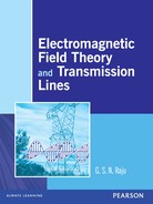
If the currents Jx, Mx produce fields Ex, Hx and if the currents Jy, My produce fields Ey, Hy in a linear and isotropic medium, then the Maxwell’s equations are:

where a = σ + jω∈, b = jωμ.
Using the properties of isotropic media, from Equation (9.3), we can write
If all the sources are contained within a finite volume, the far-fields constitute spherical waves and the surface integral of Equation (9.4) becomes zero. Hence
Equations (9.5) is written as
|
|
|
|
〈x, y〉 represents reaction of field y on the source x. Similarly, 〈y, x〉 represents reaction of x on y.
The principle of reciprocity is an inter-relationship between any two source-field pairs. Equations (9.5) and (9.6) are the expressions of such pairs. It is possible to state that if
then the reciprocity exists.
9.4 REACTION CONCEPT
If x and y represent two sets of source currents and fields, then according to the principle of reciprocity, we can write the above as
Here 〈x, y〉 is known as ‘reaction’ of field x on source, y and 〈y, x〉 is known as ‘reaction’ of field y on source x.
〈x , x〉 represents the reaction of field x on its own source x and it is known as self-reaction.
Self reaction is defined as
9.5 INDUCTION AND EQUIVALENCE THEOREMS
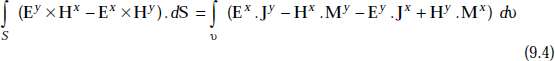
Let the region 1 represented by μ1, σ1, ∈1 contain a system of sources, S1 and let region 2 represented by μ2, σ2, ∈2 contain no sources (Fig. 9.1).
S1 indicates the presence of sources and Sf indicates source free region.
In region 1, the actual fields are (Ei + Er, Hi + Hr) and in region 2 the fields are E2 and H2.
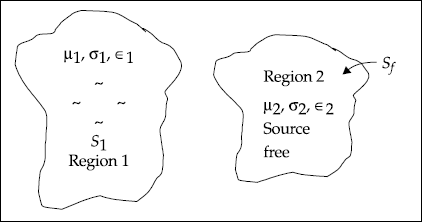
Fig. 9.1 Regions containing sources and source free regions
Induction theorem states that the induced or scattered fields are produced by electric and magnetic current sheets and the current densities are represented by
|
Js = an × Hi |
|
Ms = −an × Ei |
where |
Hi = (Ht2−Htr) |
|
Ei = (Et2−Etr) |
|
Et2 = tangential component of E2 |
|
Etr = tangential component of Er |
|
Ht2 = tangential component of H2 |
|
Htr = tangential component of Hr |
|
Ei = induced electric field |
|
Hi = induced magnetic field |
|
an = unit normal vector to the sheet |
Equivalence theorem states that current distributions and induced fields are related by
|
Js = an × Hi |
|
Ms = −an × Ei |
where |
Hi = Ht2 [Htr = 0] |
|
Ei = Et2 [Etr = 0] |
It is clear from this theorem that the Equivalence Theorem is a particular case of Induction Theorem, that is, when region 1 and region 2 have the same constants, there are no reflected waves. Under these conditions both the theorems are identical.
9.6 ELECTROMAGNETIC INTERFERENCE AND COMPATIBILITY (EMI/EMC)
EMI/EMC Engineering is a unique and specialised subject. It came into prominence with the tremendous advances in technology and proliferation of a variety of electronic instruments and devices which produce electromagnetic emissions. In fact, the world is highly saturated with such emissions from a variety of sources. The effect of such sources is spread throughout the electronic spectrum.
EMI is defined as the undesirable signal which causes unsatisfactory operation of a circuit or device.
EMC is defined as the ability of electronic and communication equipment to be able to operate satisfactorily in the presence of interference and not be a source of interference to the nearby equipment.
Electromagnetic susceptibility (EMS) is the capability of a device to respond to EMI.
Basic types of EMI These are of two types. They are:
- Intra-EMI EMI is said to be intra-EMI if the functional characteristics of one module within an electronic equipment or system is disturbed due to EMI from another module.
- Inter-EMI EMI is said to be inter-EMI if the functional characteristics of one equipment is disturbed due to EMI generated by another equipment.
9.7 EMI SOURCES
These are divided mainly into two types:
- Natural
- Man-made
I. Natural EMI sources are of the following types:
Terrestrial and Extra-terrestrial
- Terrestrial sources These are atmospheric thunderstorms, lightning discharges and precipitation static.
- Extra-terrestrial sources These are sun-disturbed and quiet, cosmic noise and radio stars.
II. Man-made EMI sources are many.
- Electric power sources These consist of:
- Generation equipment, conversion (step up/down) equipment like faulty transformers and faulty insulators.
- Transmission equipment like pick-up and re-radiation and faulty insulations.
- Distribution equipment like faulty transformers, faulty wiring, faulty insulation, poor grounding, pick-up and re-radiation.
- Electronic communication devices These are:
- Police radio
- All types of radars
- Cellular and mobile communication
- Satellite communication
- Point-to-point communication
- Television and Radio
- Machines and Tools These are:
- Industrial machines
- Electric cranes
- Fork-lift trucks
- Milling machines
- Printing presses
- Punch presses and so on
- Office/business machines
- Computers
- Cash registers
- Electronic typewriters
- Photocopiers and so on
- Welders and heaters
- Arc welders
- RF stabilised welders
- Induction heaters and so on
- Transporters
- Elevators
- Escalators
- Conveyer belts and so on
- Power tools
- Appliances
- Air-conditioners
- Refrigerators
- Microwave ovens
- Vacuum cleaners
- Electric lawn mowers and so on
- Industrial machines
- Ignition systems
- Engines
- Vehicles
- Automobiles
- Aircrafts
- Tanks
- Trucks
- Tractors and so on
- Tools
- Auxiliary generators
- Lawn mowers
- Portable saws and so on
- Consumer and medical electric systems
- Lights
- Fluorescent lamps
- Faulty incandescent lights
- Neon lights
- RF excited gas displays
- Light dimmers and so on
- Entertainment
- Home computers
- Cassette players/recorders
- Television receivers
- Appliances
- Electric shavers
- Washing machines
- Grinders/mixers
- Vacuum cleaners
- Medical equipment
- X-ray machines
- Defibrillators
- Ultrasonic scanners
- Scanners
- Lights
- Nuclear These are:
- Nuclear submarines, ships and nuclear aircraft
- Nuclear detonators
- Nuclear power stations
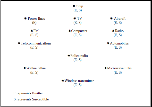
The devices which are susceptible to EMI are listed below.
EMI is coupled in two ways:
- By conduction—Here the EMI is routed along power supply and signal lines.
- By radiation—Here the EMI is coupled through radiation from wires and antennas. This can be either through near-fields or far-fields.
9.8 EFFECTS OF EMI
EMI is considered to be a silent and unknown threat. On many occasions, intermittent malfunctions or random failures of equipment are experienced by several users. They are attributed to be due to the presence of EMI. In view of this, the threat due to EMI is silent and has proved to be hazardous.
Common effects of EMI
- Annoying effects Very often, momentary and random disturbances occur in radio and television reception.
- Disturbing effects EMI causes unwanted reset and change of status in settings in computers and digital equipment. Malfunctioning of computer keyboards is also noticed.
- Catastrophic situations Burning of electronic components, loss of data, change of threshold settings, improper or unwanted operations and sometimes biological hazards occur very often due to EMI.
9.9 METHODS TO ELIMINATE EMI OR DESIGN METHODS FOR EMC
The effective methods to eliminate EMI are:
- Shielding
- Grounding
- Bonding
- Filtering
- Isolation
- Separation and orientation
- Circuit impedance level control
- Cable design
- Cancellation techniques in frequency or time domain
- Proper selection of cables, passive components
- Antenna polarisation control
- Balancing
The first four methods are popular for different applications. A few basics are presented below.
Shielding
The main object of shielding is to restrict radiations to a specified region to prevent it from entering susceptible devices. The quality of shielding is expressed in the form of shielding effectiveness of the material. Shielding of materials can be solids, screens and braids. They can be in the form of boxes, partitions, cables and connector shields.
Shielding effectiveness (Se) It is defined as the ratio of incident power to transmitted power.
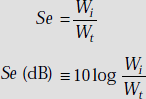
For electric fields, we have
For magnetic fields,
The shielding effectiveness for electric fields in dB can be written as the sum of three terms, that is,
| Se(dB) | = | RdB + AdB + MdB | |
| where | RdB | = | reflected loss |
| AdB | = | absorption loss | |
| MdB | = | multiple re-reflections and transmission losses |
Shielding is done by good conducting materials. Some examples of shielding materials are silver, copper, aluminium, gold, brass and bronze.
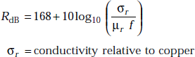
Reflection loss is very high at low frequencies and for high conductivity materials.
It is expressed as
The absorption loss for the materials (μr σr >> 1) is given by
|
AdB |
= |
8.6859 t / δ |
where |
t |
= |
thickness of the shield |
|
δ |
= |
depth of penetration |
The multiple reflection loss is given by
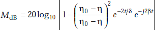
MdB is negligible for shields made of good conductors (ƞ << ƞ0). If t >> δ and ![]() .
.
The effective magnetic shielding materials are the ones with high permeability. Examples: Mumetal, Steel.
Grounding
Grounding provides a conducting path between electronic devices and the ground. Ground is nothing but some reference point. It is a circuit concept.
The ideal ground is characterised by zero potential and impedance.
The types of grounding techniques are:
- Floating ground: It isolates circuits from a common ground plane. Sometimes it may be hazardous.
The ground plane is in the form of a wire or a conductive rod.
- Single-point grounding: It reduces the effects of facility ground currents. This is used to control EMP energy.
- Multiple point grounding: It reduces ground lead lengths.
Bonding
It provides a low-impedance path between two conducting surfaces. It is a part of grounding and represents its physical implementation.
It creates a homogeneous structure for current flow and suppresses the creation of potentials between two metallic parts.
Bonding is useful to protect against the effects of shocks and to protect circuits from current return paths. They reduce potential difference between the devices and carry large faulty currents.
Bonding is of two types:
Direct bonding is made by metal-to-metal between the connected elements. Indirect bonding is made by contact using conductive jumpers.
Bonding quality is represented by its DC and AC resistances and also bonding effectiveness.

where |
l |
= |
length of the bond, (m) |
|
σ |
= |
conductivity, (mho/m) |
|
s |
= |
cross-sectional area, (m2) |
|
δ |
= |
depth of penetration, (m) |
|
w |
= |
width of the bond, (m) |
Bonding effectiveness (Be) It is defined as the difference between induced voltage in the case of an equipment with a bond trap and the induced voltage in the case of an equipment without a bond trap. It is expressed in dB.
Filtering
These are used to filter out conducted EMI. The filtering effectiveness is expressed by Insertion loss (IL). It is defined as
where |
V01 |
= |
output voltage with filter |
|
V02 |
= |
output voltage without filter |
For low pass inductive filters,
Insertion loss ![]()
For low pass capacitive filter,
Insertion loss ![]()
where ω = angular frequency = 2π f
9.10 NEED FOR EMC STANDARDS
EMC standards are required for trouble free co-existence and to ensure satisfactory operation. They are also required to provide compatibility between electrical, electronic, computer, control and other systems. Standards are required as manufacturer-user interaction and user’s knowledge on EMI are limited.
They are also required for establishing harmonised standards to reduce international trade barriers and to improve product reliability and life of the product.
9.11 EMC STANDARDS
These are of two types:
Military Standards
These include emission and susceptibility standards. Emission standards specify emission limits in voltage or current, power or field strengths in specified frequency ranges. Susceptibility standards specify conducted spike or radiated field parameters.
Military EMC standards are made in order to ensure system-to-system compatibility in a real time military environment. Equipments are classified based on their deployment environment. In these standards, test procedures are well defined. Military standards are more stringent than civilian standards. Most of the military standards are broadly based on MIL-STD 461 and 462.
Civilian Standards
Civilian EMC standards are applicable for equipments used for commercial, industrial and domestic applications. The emission standards are specified to protect broadcast services from interference. These also take into account the physiological interference effects experienced by human beings.
9.12 ADVANTAGES OF EMC STANDARDS
The advantages are:
- Compatibility, reliability and maintainability are increased.
- Design safety margin is provided.
- The equipment operates satisfactorily in EMI scenario.
- Product life is increased.
- Higher profits are possible.
9.13 EMC STANDARDS IN DIFFERENT COUNTRIES
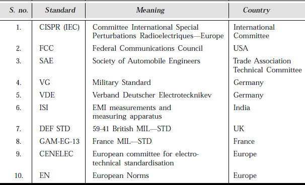
9.14 BIOLOGICAL EFFECTS OF EMI/EMR (ELECTROMAGNETIC INTERFERENCE, ELECTROMAGNETIC RADIATION)
EM waves, light, heat, X-rays and gamma rays are all different forms of electromagnetic radiation. However, they differ in their wavelength. These radiations have hazardous effects on man and material. The effects can be divided into two categories:
- Thermal Effects
- Non-thermal Effects
- Thermal Effects The effects of EM radiation whose frequencies range between 0.1 to 100 GHz are given in Table 9.1.
Table 9.1 Effects of EM Radiation
Frequency
(GHz)Effect 0.1
Warming of exposed areas.
0.15−1.2
Overheating occurs and causes damage to internal organs.
1.0−3.3
Lens of the eye and kidneys are susceptible to damage when tissues are heated up.
3.3−10
Noticeable skin heating occurs.
10−100
Skin acts as either a reflector or an absorber and hence heating takes place.
The damaging levels depend on frequency, ambient temperature, body resistance and weight of individuals.
Exposure over an energy density of 10 mw/cm2 at any frequency is considered to be not safe.
- Non-thermal Effects
- Minor changes in human blood properties take place.
- Buzzing sound is heard upon exposure to EMR.
- Abnormalities of the chromosome structure occurs.
- Movement, orientation and polarisation of protein molecules are noticed.
- Epigastric distress, emotional upsets and nausea have been noticed.
Radiation limits in the frequency range of 0.1 to 100 GHz when personnel are exposed to EM radiations are:
- The average incident power density should not exceed 10 mw/cm2 for exposures greater than 30 seconds.
- The average incident energy density should not exceed 300 mJ/cm2 for intermittent exposures between 3 and 30 seconds.
- According to IEEE, safe power density level is 2 W/m2.
9.15 ELECTROSTATIC DISCHARGE (ESD)
ESD results from the separation of static charge.
Effects of ESD:
- High electrostatic field is created by the charge separation prior to the ESD arc.
- High arc discharge currents are generated.
Methods of Separation of Charge
Rubbing of two types of insulating material causes charge to be separated from one material to the other. The charge separation creates high fields and hence causes a voltage difference between the two materials. This leads to a breakdown of the air and intensive arcs are produced. A direct conduction path will result if one material comes in contact with a conductor. This phenomenon is a familiar one when we walk across a carpet on a dry day and touch a metallic doorknob. When the resulting arc current enters sensitive devices, they are damaged.
9.16 ORIGIN OF ESD EVENT
If two neutral insulators are brought in contact, charge is transferred from one to another. When they are separated, they become charged. At this time, one material is positively charged and the other one is negatively charged. The degree of charge transfer depends on many factors. For example, if Nylon is rubbed against Teflon, electrons will be transferred from Nylon to Teflon. Hence Nylon acquires (+)ve charge and Teflon acquires (–)ve charge.
In fact, touching an insulator with a conductor creates charge separation but the degree is less than that of two insulators.
Grounding a conductor will bleed off the charge but grounding an insulator will not.
ESD wrist straps can be worn to prevent building up of charge.
If a high resistance of the order of 1 MΩ is connected from the installer’s wrist to earth ground, any static charge stored on the body’s skin is discharged to the ground.
It is interesting to know some facts about the frictionally generated charges.
- Sparks with a voltage of about 5 KV are generated when a man walks on a rug on a dry day, touches a metallic body and hits. Nothing happens to the man as the charge is less even when the voltage is high. On the other hand, when the charge is high with less generated voltage, it can be fatal.
- The charges attract dust particles and damage electronic chips and circuits.
- They may cause fire and explosion in inflammable environment.
ESD causes component destruction by:
- direct conduction
- secondary arcs or discharges
- capacitive coupling
- inductive coupling
The techniques to prevent the ESD effects are:
- Prevent occurrence of ESD event
- Prevent coupling
- Create an inherent immunity to ESD event.
9.17 ELECTROMAGNETIC PULSE (EMP)
Whenever a nuclear detonation takes place, energy is released and this appears as electromagnetic pulse. These pulses affect the operation of electrical and electronic equipment even at great distances. The far-field characteristics of the radiated EMP produced by a single high altitude detonation is found to have significant variation in amplitude, wave shape and propagation characteristics. These depend on weapon yield, location of the observer, the height and location of the burst and orientation of earth’s magnetic field.
The EMP amplitude spectrum covers a broad frequency range which extends from low to microwave frequencies.
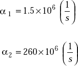
A typical EMP waveform can be represented by
where |
t |
= |
time in seconds |
|
a |
= |
normalisation factor = |
|
t1 |
= |
time to peak value |
|
Em |
= |
E(t1) |
The Fourier transform of the equation is
A typical EMP wave form is shown in Fig. 9.2.
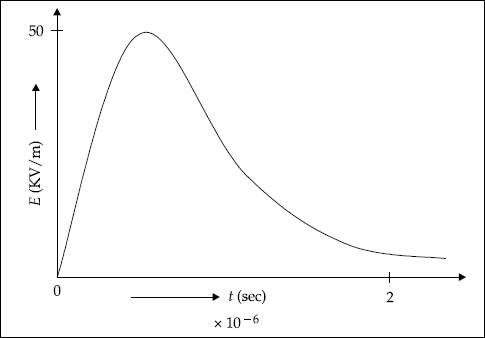
Fig. 9.2 A typical EMP wave form
9.18 NUMERICAL TECHNIQUES FOR THE ANALYSIS OF ELECTROMAGNETIC FIELDS
Most of the engineering problems/models are in the form of differential equations. Systems with one independent variable can be modeled by ordinary differential equations. But systems with two or more independent variables require the use of partial differential equations. It is possible to obtain the solution for some of these equations in closed form. But majority of the large sets of simultaneous differential equations and non-linear ones do not have analytical solutions and hence the application of numerical techniques is required.
The most useful numerical techniques are:
- Finite Difference Method (FDM)
- Finite Element Method (FEM)
- Method of Moment (MOM)
In all these methods, discretisation of a continuous region into a finite number of sections is made. Moreover, they require the solution of a set of algebraic equations only. The solution of differential or integral equations is not required. These methods are extremely useful for the design as well as analysis of an electromagnetic system. Problems involving the determination of current distribution in a current element or a dipole and the field distribution in a slot are easily solved by these methods.
For modeling static field systems, Laplace’s and Poisson’s equations can be used. These require the solution of differential equations. It is possible to obtain analytical solutions when the regions have regular geometrical shapes like triangular, circular, elliptical, rectangular and so on. But for arbitrarily shaped regions, the field solutions are obtained using FDM, FEM and MOM techniques.
9.19 FINITE DIFFERENCE METHOD (FDM)
It is a numerical technique in which the domain is divided into a number of discrete points. It consists of a set of difference equations. FDM is useful to solve the spatial distribution of electromagnetic fields in different media.
Solution by this method is approximate and error can be reduced by taking more number of discrete points in a specified region. For example, Poisson’s equation can be solved for V (x, y, z) in any arbitrary region using the boundary conditions. However, the analysis for fields in an arbitrarily shaped region is complex by this method.
9.20 FINITE ELEMENT METHOD (FEM)
FEM is a technique useful to solve the problems containing differential equations numerically. This method is easily applicable to solve the problems involving arbitrarily shaped regions. The method basically consists of:
- discretisation of the field region
- derivation of equations for each element
- assembling of all elements in the field region
- solving the set of equations
Solution can be obtained either by Iterative method or by Band matrix method.
FEM is a better method than FDM and MOM as it is easy to apply to complex regions and it is possible to write universal general purpose programmes to solve different types of problems. At the same time, it is constrained by a few drawbacks. For instance, the preparation of data is complex and involved. The programming part is also involved compared to FDM and MOM.
9.21 METHOD OF MOMENTS (MOM)
It is basically an incremental numerical technique. It is useful to find the integrand from the integral equation. An equation is known as an integral equation if the integrand is an unknown.
This method makes use of equations of unknown potentials or fields in integral form to find out the potential or field distribution in a medium.
An example of integral equation is
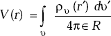
where ρν (r′) is an unknown.
r′ = (x′, y′, z′), r = (x, y, z)
ρυ (r′) = ρυ (x′, y′, z′)
V(r) = V(x, y, z)
ρʋ is the source of the potential function. r is the distance between the source and potential. ρʋ is an unknown function and V is a known function. The method of moments consists of the following steps:
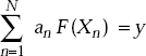
- Express the integral equation of the potential function in the form of
F (X) = y
where F is an integral operator and y is a known function.
X is an unknown output function.
- Expand X as a linear combination of N terms, that is,
X(x) = a1 X1 (x) + a2 X(x) +… + aN Xn (x)
where aN is an unknown constant and XN (x) is a known function and is called a basis or expansion function.
- Express F in the form of
This consists of one equation with N unknowns. It is not possible to solve it as such. It is required to have N independent linear equations. Hence, applying boundary conditions at N points, we have N equations.
- Express the above summation in the form of
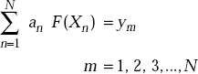
- Express the above expression in Matrix form, that is,
[Fmn] [an] = [ym]
- Find an from
[an] = [Fmn]–1 [ym]
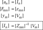
For the sake of analogy, we can have
SOLVED PROBLEMS
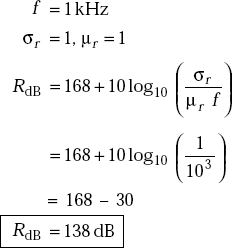
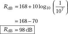
Problem 9.1 For a copper shield, find the reflection loss in dB at (a) 1 kHz and (b)10 MHz.
Solution
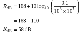
Problem 9.2 Determine reflection loss for a steel shielding at (a) 10 kHz and (b) 10 MHz. For steel, μr = 1,000, σr = 0.1.
Solution
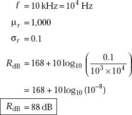
- f = 10 MHz
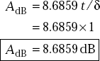
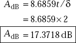
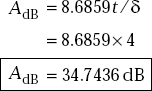
Problem 9.3 For nickel shield, find the absorption loss when t / δ = 1, t/ δ= 2, t / δ = 4.
Solution If t / δ= 1
If t / δ = 2
If t / δ =4
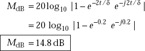
Problem 9.4 Find multiple reflection loss due to a shielding material for which ƞ<<ƞ0 and t / δ = 0.1.
Solution We have
POINTS/FORMULAE TO REMEMBER
- The General form of second Maxwell’s equation is ∇ × E = −Ḃ − M.
- The surface electric current density is Js = an × H.
- The surface magnetic current density is Ms = E × an.
- The vector electric potential is defined as
- Self-reaction is defined as
- The principle of reciprocity gives an inter-relationship between any two-source field pairs.
- By reciprocity, 〈x, y〉 = 〈y, x〉.
- Most of the devices and systems are sources of EMI and also they are susceptible.
- Systems should be EMC designed for long life.
- EMI sources are natural and man-made.
- Domestic electric appliances are sources of EMI.
- Automobiles are sources of EMI.
- Medical devices and instruments are susceptible to EMI.
- Shielding, grounding, bonding, isolation and filtering are the major EMC design techniques.
- Military and civilian EMC standards are different in EMI permissible limits.
- FEM, FDM and MOM are important numerical techniques.
- ESD is more hazardous during lightning.
- An electric current loop is equivalent to a magnetic dipole.
- The electromagnetic fields produced by a small horizontal electric current loop are identical to that of a vertical magnetic dipole.
- The fields produced by magnetic current loop and electric dipole are the same.
OBJECTIVE QUESTIONS
1. Electric power lines are sources of EMI. |
(Yes/No) |
2. Computers are susceptible to EMI. |
(Yes/No) |
3. Walkie Talkies radiate and they are susceptible to EMI. |
(Yes/No) |
4. Automobiles are sources of EMI. |
(Yes/No) |
5. Aircraft is not susceptible to EMI. |
(Yes/No) |
6. Submarines are not susceptible to EMI. |
(Yes/No) |
7. Radar is a man-made source of EMI. |
(Yes/No) |
8. Human beings are susceptible to EMR. |
(Yes/No) |
9. Animals are susceptible to EMR. |
(Yes/No) |
10. Medical equipment is susceptible to EMI. |
(Yes/No) |
11. Kitchen mixie is a source of EMI. |
(Yes/No) |
12. Hair drier is a source of EMI. |
(Yes/No) |
13. Television is susceptible to EMI. |
(Yes/No) |
14. Fluorescent lamp is a source of EMI. |
(Yes/No) |
15. Isolation is a method of EMI control. |
(Yes/No) |
16. Grounding is a method of EMC design. |
(Yes/No) |
17. Proper cable design reduces EMI. |
(Yes/No) |
18. Washing machines are sources of EMI. |
(Yes/No) |
19. Light dimmers in automobiles are sources of EMI. |
(Yes/No) |
20. Cell phones are sources of EMI. |
(Yes/No) |
21. FEM is more useful than FDM. |
(Yes/No) |
22. FEM is a numerical technique using a set of algebraic equations. |
(Yes/No) |
23. Numerical evaluation of integrals is more accurate than the numerical evaluation of differential equations. |
(Yes/No) |
(Yes/No) |
|
25. If 〈x, y〉 = 〈y, x〉 reciprocity is said to exist. |
(Yes/No) |
26. It is easy to shield electric fields than to shield magnetic fields. |
(Yes/No) |
27. Reflection loss is very large for electric fields and plane waves. |
(Yes/No) |
28. Reflection loss is usually small for low frequency magnetic fields. |
(Yes/No) |
29. Shielding is said to be excellent, if the attenuation is > 90 dB. |
(Yes/No) |
30. The unit of magnetic conduction density is _____. |
|
31. The unit of surface magnetic current density is _____. |
|
32. Surface magnetic current density is defined as _____. |
|
33. Vector electric potential, F is defined by _____. |
|
34. The unit of vector electric potential is _____. |
|
35. The unit of reaction is _____. |
|
36. Self-reaction is represented by _____. |
|
37. Reciprocity in field theory is said to exist if _____. |
|
38. EMI means _____. |
|
39. EMC represents _____. |
|
40. EMS means _____. |
|
41. EMI is mainly from _____. |
|
42. EMI enters the system by _____. |
|
43. EMI can be controlled by _____. |
|
44. EMI from antennas can be controlled by _____. |
|
45. Filtering is a technique suitable to control _____. |
|
46. Two types of EMC standards are _____. |
|
47. FCC means _____. |
|
48. CISPR represents _____. |
|
49. The main advantage of EMC standards is that _____. |
|
51. The main effects of EMI/EMR are _____. |
|
52. High EMR susceptible organs of human beings are _____. |
|
53. ESD means _____. |
|
54. ESD originates due to _____. |
|
55. The safe EMR exposure limit is _____. |
|
56. The effect of ESD is that _____. |
|
57. ESD causes _____. |
|
58. EMP means _____. |
|
59. The damaging levels due to EMR in human beings depend on _____ |
|
60. Two major sources of EMI are _____. |
|
61. FDM means _____. |
|
62. FEM represents _____. |
|
63. MOM means _____. |
|
64. The unit of self-reaction is _____. |
|
Answers
1. Yes |
2. Yes |
3. Yes |
4. Yes |
5. No |
6. No |
7. Yes |
8. Yes |
9. Yes |
10. Yes |
11. Yes |
12. Yes |
13. Yes |
14. Yes |
15. Yes |
16. Yes |
17. Yes |
18. Yes |
19. Yes |
20. Yes |
21. Yes |
22. Yes |
23. Yes |
24. Yes |
25. Yes |
26. Yes |
27. Yes |
28. Yes |
29. Yes |
30. V/m2 |
|
|
31. V/m |
32. Ms= E × a n |
33. ∇ × F ≡ −∈Em |
34. Farad-Volt/m |
35. Watts |
36. 〈x, x〉 |
37. 〈x, y〉 = 〈 y, x〉 |
38. Electromagnetic interference |
|
39. Electromagnetic compatibility
40. Electromagnetic susceptibility
41. Man-made and natural sources
42. Conduction and radiation
43. Shielding
44. Polarisation control
45. Conducted EMI
46. Military and civilian
47. Federal Communications Council
48. Committee International Special Perturbations Radioelectriques
49. Product life is increased
50. German EMC standard
51. Thermal and non-thermal
52. Eyes and kidneys
53. Electrostatic discharge
54. Separation of static charges
55. 10 mW/cm2 for exposures greater than 30 seconds
56. Intense arc discharge current takes place
57. Component destruction
58. Electromagnetic pulse
59. Frequency and ambient temperature
60. Nuclear detonations and lightning
61. Finite difference method
62. Finite element method
63. Method of moment
64. Watt
MULTIPLE CHOICE QUESTIONS
- Maxwell’s equation is
- ∇ × E = −Ḃ + J
- ∇ × E = −Ḃ − M
- ∇. E −Ḃ
- ∇. D = − B
- The unit of magnetic conduction current density is
- V/m
- V/m2
- A/m2
- A/m
- The unit of surface magnetic current density is
- A/m
- V/m
- A/m2
- A/m3
- According to reciprocity in EMF theory
- 〈 x, y〉 = 〈y, x〉
- 〈 x, y 〉 ≠ 〈y, x〉
- 〈 x, y 〉 = 〈x, z〉
- 〈 z, x 〉 = 〈y, z〉
- Self-reaction is defined by
- The unit of self-reaction is
- watts
- watts/m2
- volt-amp
- amper2
- The surface electric conduction current density is
- Js = a n × H
- Js = H × a n
- Js = an . H
- Js = H
- The surface magnetic conduction density is
- M = a n × E
- M = −a n × E
- M = E . a n
- M = E
- The system which is not susceptible to EMI is
- transmission lines
- computer keyboard
- television
- aircraft
- Radar is
- conventional EMI source
- natural EMI source
- not an EMI source
- unconventional EMI source
- Lightning is
- a source of EMI
- a natural source of EMI
- a man-made source of EMI
- is not a source of EMI
- EMI occurs in a system due to antenna by
- conduction
- radiation
- filtering
- isolation
- EMC method is
- shielding
- conduction
- radiation
- non-conduction
- American EMC standard name is
- FCC
- VDE
- ISI
- VG
- Bio-effects are more prominent in the frequency range of
- HF
- UHF
- Microwave
- LF
- EMR effects are not prominent in
- human beings
- semiconductors
- conductors
- insulators
- FEM is
- empirical method
- numerical method
- analytical method
- none of these
- EMI is more hazardous in
- television
- radars
- spacecrafts
- trains
- Cell phones create
- conducted EMI
- radiated EMI
- filtering
- shielding
- VDE is EMC standard in
- America
- India
- Japan
- Germany
Answers
1. (b) |
2. (b) |
3. (b) |
4. (a) |
5. (b) |
6. (a) |
7. (a) |
8. (b) |
9. (a) |
10. (a) |
11. (a) |
12. (b) |
13. (a) |
14. (a) |
15. (c) |
16. (d) |
17. (b) |
18. (c) |
19. (b) |
20. (d) |
EXERCISE PROBLEMS
- For silver shield, find the reflection loss in dB at
- 1 kHz
- 10 MHz
- 100 MHz
μr = 1, σr = 1.05 for silver.
- Find the reflection loss for aluminium shielding at
- 100 kHz
- 10 MHz
For aluminium, μr = 1, σr = 0.61.
- Determine absorption loss when t / δ = 1.3, t / δ = 2.5, t / δ = 3 for steel shield.
- Find the multiple loss due to a shielding material for which ƞ = 10Ω and t / δ = 0.2, t / δ = 0.4.