Chapter 6
Guided Waves
The propagation characteristics of guided waves are different from wave propagation characteristics in free space.
The main objective of this chapter is to provide the conceptual behaviour of EM waves in guided structures. The topics include:
- fields and propagation characteristics between parallel plates
- fields and propagation characteristics in hollow rectangular and circular waveguides
- TE, TM and TEM waves
- cavity resonators
- solved problems, points/formulae to remember, objective and multiple choice questions and exercise problems.
6.1 INTRODUCTION
In the previous chapter, propagation characteristics of uniform plane waves in free space were considered. These characteristics are very important when waves propagate between transmitter and receiver in free space. However, there are practical situations where propagation is by means of guided waves, that is, the EM waves may be guided between conducting planes or along a pair of wires or coaxial transmission lines. They may also be guided in wave-guide structures. In these cases, the medium of propagation is not free space.
6.2 WAVES BETWEEN PARALLEL PLATES
In these structures, the waves are no more uniform plane waves. Hence their propagation characteristics are described in terms of Transverse Electric (TE) and Transverse Magnetic (TM) waves.
6.3 DERIVATION OF FIELD EQUATIONS BETWEEN PARALLEL PLATES AND PROPAGATION PARAMETERS
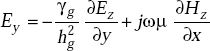
Consider Fig. 6.1.
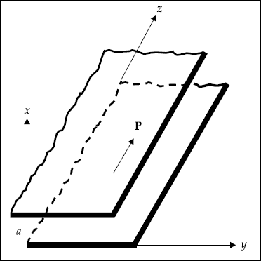
Fig. 6.1 Parallel conducting plates
Assume that:
- the plates are extended to infinity in y and z-directions
- the plates are perfectly conducting
- the plates are separated by a distance of ‘a’ metres in x-direction
- the space between the plates is air or free space
- the direction of power flow is z
- all field components in z-direction vary as
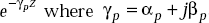 . Here γp is the propagation constant, αp is the attenuation constant and βp is the phase constant. In time varying form the fields vary as

- the field is uniform in y-direction as the plates are extended to infinity in y-direction
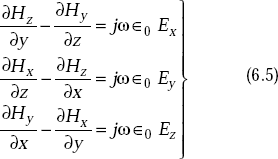
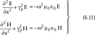
As the medium between the plates is air, the first and second Maxwell’s equations are given by
and
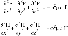
The corresponding wave equations in air are:
and
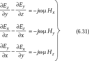
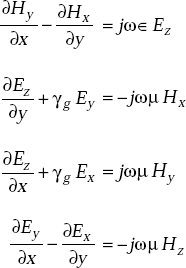
Expanding Equation (6.1), we get
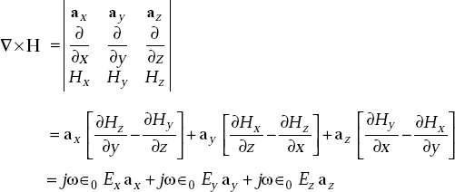
Equating the respective components on either side, we get
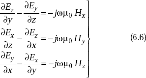
Similarly, expanding Equation (6.2) and equating the respective components on both sides, we get
If H = H0, at z = 0, the field components can be written as
and similarly
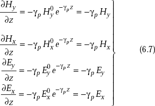
and
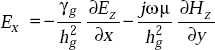
Substituting Equation (6.7) in Equations (6.5) and (6.6), we get
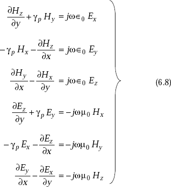
But all terms containing derivatives with respect to y vanish as the fields do not vary with y. Hence Equation (6.8) becomes
As E can be written as
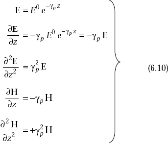
and similarly
The wave equations
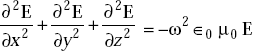
and
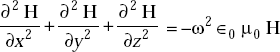
and become
or,
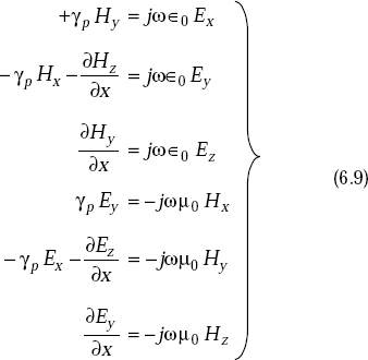
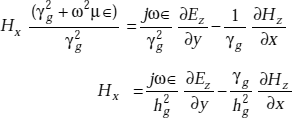
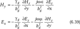
Solving Equation (6.9) simultaneously, we get the field components as
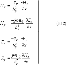
where
It is seen from Equation (6.12) that if Ez = 0, Hz = 0 as in the case of uniform plane wave, all the components will vanish. Therefore, there should be either E or H in the direction of propagation. In view of this, the solution is divided into two parts:
- Transverse Electric waves (TE waves) In this Ez = 0 and Hz ≠ 0.
- Transverse Magnetic waves (TM waves) In this Hz = 0 and Ez ≠ 0.
6.4 FIELD COMPONENTS FOR TE WAVES (EZ = 0)
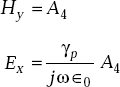
TE wave means transverse electric wave for which there is no component of E in the direction of propagation, or, Ez = 0.
For this case, as Ez = 0, it is obvious from Equation (6.12) that Hy = 0 and Ex = 0. Substituting these values in Equation (6.11), we get the component of y as,
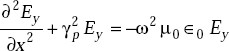
that is,

or,
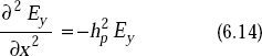
or,
where
This equation has the solution in the form of
where A1 and A2 are constants.
Using the boundary condition, Ey = 0 at x = 0, A2 is zero.
So,
At x = a, Ey = 0 requires that
Here if m = 0, all the field components vanish.
Thus,
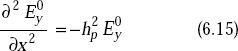
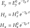
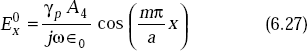
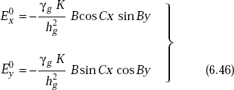
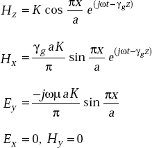
Substituting Equation (6.19) in Equation (6.18), the other components are obtained. The resultant expressions for the field components are:
These represent the fields for TEm.
The field components in complete form are:
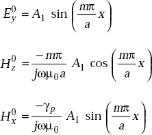
The instantaneous electric and magnetic fields for TE1 wave at some instant of time are shown in Fig. 6.2.
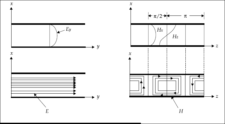
Fig. 6.2 Electric and magnetic fields between parallel plates for TE1 wave
TE waves are represented in the form of TEm where m represents variation along x.
6.5 FIELD COMPONENTS OF TM WAVES (HZ = 0)
TM wave means transverse magnetic wave for which there is no component of magnetic field in the direction of propagation, or, Hz = 0.
The wave equation for y-component of H from Equation (6.11) can be written
or,
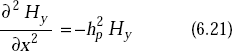
where
The solution of Equation (6.21) appears in the form of
As the tangential component of H is not zero at the surface of a conductor, the boundary condition cannot be applied directly to Hy to obtain A3 and A4. From Equation (6.9) we have
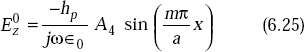
Putting Equation (6.22) in Equation (6.23), and writing the equation for Ez, we get
The boundary conditions are:
Applying the first boundary condition, A3 becomes zero. For the second boundary condition, Ez = 0 at x = a. Ez becomes zero if
Here, m= 0 is also possible as there still exist some more components.
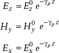
From Equations (6.9) and (6.25) we get the remaining components Hy and Ex. As a whole, the expressions of field components for TM waves are:
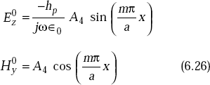
The field components in complete form for TMm waves are:
The field variations for TM1 wave between parallel plates are shown in Fig. 6.3.
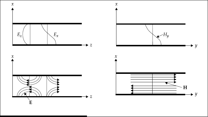
Fig. 6.3 The TM1 wave between parallel plates
Dominant mode or wave It is defined as a mode TE1 which has the lowest cut-off frequency.
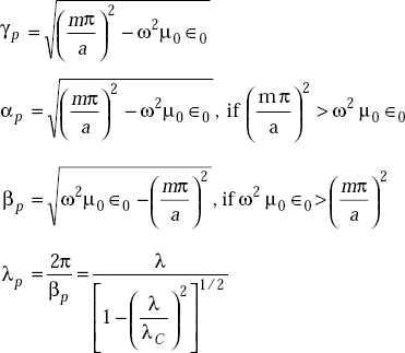
6.6 PROPAGATION PARAMETERS OF TE AND TM WAVES
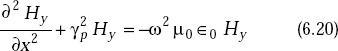
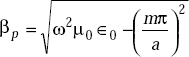
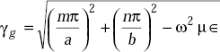
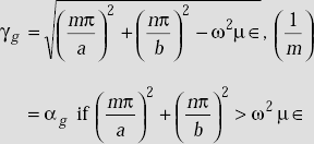
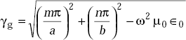
We have the expression for propagation of TE and TM waves as
where ![]()
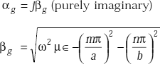
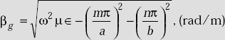
If ![]() , γp will be purely imaginary, or,
, γp will be purely imaginary, or,
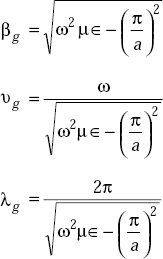
βp is the phase constant
So,
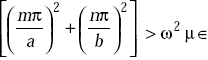
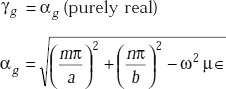
If 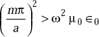 , γp will be purely real, or,
αp is the attenuation constant
So,
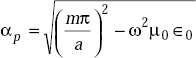
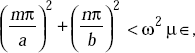
For all frequencies less than ωc,
where ![]()
γp is real and βp = 0.. This means that fields will be attenuated exponentially in z-direction and there is no wave motion as βp = 0.
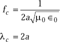
At f > fc, γp = jβp, wave motion takes place and αp = 0. This fc is known as cut-off frequency.
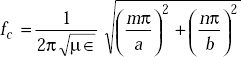
Cut-off frequency (fc)
Definition Cut-off frequency, fc is defined as a frequency below which there exists only attenuation and βp = 0 and above which αp = 0 and βp exists.
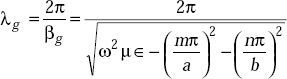
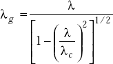
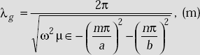
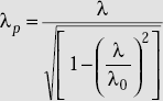
6.7 GUIDE WAVELENGTH
Wavelength between the plates is ![]()
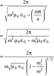
But ![]() free space wavelength
free space wavelength
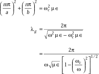
where
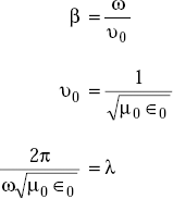
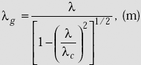
Now
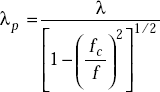
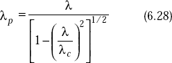
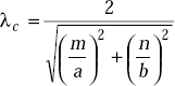
where λc = cut-off wavelength
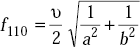
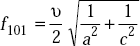
The propagation parameters are:

For TE1
6.8 TRANSVERSE ELECTROMAGNETIC WAVE (TEM WAVE)
Definition 1 TEM wave is a wave for which there are no components of E and H in the direction of propagation.
Definition 2 TEM wave is a TMm wave for m = 0, or, TEM = TEM0.
TEM wave is called principal wave.
The field components of TEM wave are obtained from m = 0. They are:
The propagation parameters for TEM wave are
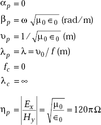
TEM wave between parallel plates are given in Fig. 6.4.
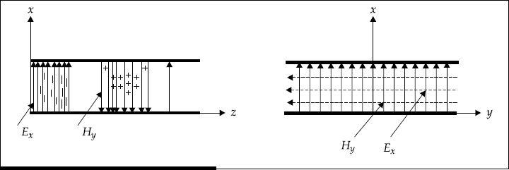
Fig. 6.4 TEM wave fields between parallel plates
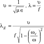
6.9 VELOCITIES OF PROPAGATION
Free space velocity (υ0) It is defined as the velocity of propagation of an EM wave in free space.
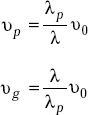
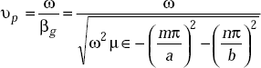
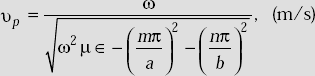
Phase velocity (υp) It is defined as the velocity of propagation of equiphase surfaces along the guide.
Group velocity (υg) It is defined as the velocity with which energy propagates in a waveguide.
The phase velocity in a waveguide is always greater than free space velocity.
In free space, velocity of propagation is equal to the phase velocity.
Group velocity in waveguide is less than free space velocity.
The velocities of propagation are related by
where
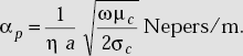
6.10 ATTENUATION IN PARALLEL PLATE GUIDES
Attenuation factor in general
Attenuation factor for TEM wave,
where |
a = plate separation, m |
|
σc = conductor conductivity, mho/m |
|
μc = conductor permeability, H/m |
|
ω = 2π f |
|
ηp = intrinsic impedance, Ω |
Attenuation factor is also given by
where |
R = resistance, Ω/m |
|
z0 = characteristic impedance, Ω |
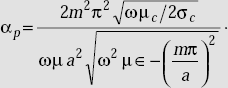
Attenuation of TE waves
where |
m = 1, 2, 3, … |
|
ω = 2π f |
|
μ = permeability of medium between plates |
|
∈ = permittivity of medium between plates |
6.11 WAVE IMPEDANCES
Wave impedances at any point between parallel plates are defined by the following relations:
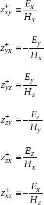
These wave impedances can be evaluated from field expressions. For example,
Problem 6.1 If a wave of 6 GHz is propagating between two parallel conducting plates separated by 30 mm, find the cut-off wavelength, guide wavelength for TE1 mode.
Solution Frequency of the wave,
Plate separation,
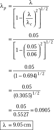
Cut-off wavelength for TE1 is
Free space wavelength,
The guide wavelength
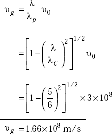
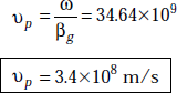
Problem 6.2 When a wave of 6 GHz propagates in parallel conducting plates separated by 3 cm, find the phase velocity, group velocity of the wave for the dominant wave.
Solution Frequency of the wave,
|
f = 6 GHz |
Plate separation, |
a = 3 cm |
|
|
|
λ = 5 cm |
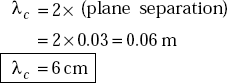
Cut-off wavelength, |
λc = 2 × a = 2 × 3 = 6 cm |
Phase velocity,
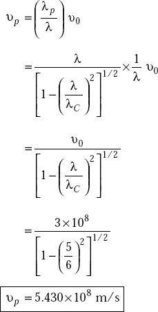
Group velocity,
Problem 6.3 When a wave of 6 GHz is to be propagated between two parallel conducting plates separated by 60 mm, find the modes that will propagate through the guide.
Solution The modes which have their cut-off frequencies less than the frequency of the wave will propagate.
Here, plate separation, |
a = 60 mm = 6.0 cm |
|
f = 6 GHz = 6 × 10⁹ Hz |
|
|
|
|
As fc < f, TE1 propagates. |
|
|
|
It propagates. |
|
|
|
As fc > f, it does not propagate. |
|
|
|
As fc > f, this will not propagate. |
|
6.12 WAVES IN RECTANGULAR WAVEGUIDES
A rectangular waveguide is a hollow metallic device with four sides closed and two sides open. It can be used as
a radiator
a high pass filter
a transmission line
a feed element to antennas
A hollow rectangular waveguide supports only TE and TM waves/modes and it does not support TEM mode.
6.13 DERIVATION OF FIELD EQUATIONS IN RECTANGULAR HOLLOW WAVEGUIDES
Field expressions can be obtained from the solutions of Maxwell’s equations and wave equations.
Assumptions:
Space inside the waveguide is free space or air.
The walls of the waveguides are perfectly conducting.
The direction of propagation of power is z.
The dimension of the narrow wall is b metres.
The dimension of the broad wall is a metres.
The fields in z-direction vary as

As the medium inside the waveguide is air, the first and second Maxwell’s equations are given by
Expanding these equations, we get
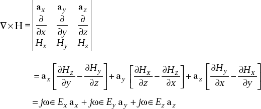
Equating the respective components, we get
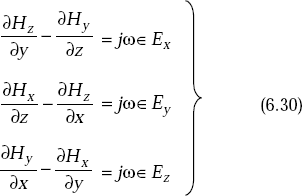
and
As the fields are assumed to be varying in the form of ![]() , combining time variation, we get
, combining time variation, we get
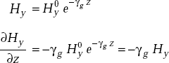
Similarly,
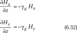
and ![]()
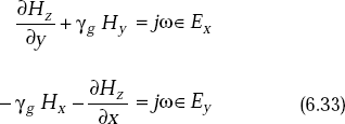
Substituting Equation (6.32) in Equations (6.30) and (6.31), we get
The wave equations are:
These can be written as
The wave equations for Ez and Hz are given by
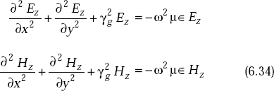
Equation (6.33) can be mathematically manipulated to get the following. Consider
and
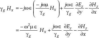
Equation (6.35) becomes
But Ey from Equation (6.36) is
From Equations (6.37) and (6.38), we get
or,
or,
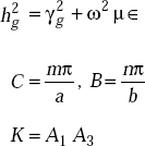
where ![]()
Similarly,
In the above equations, if Ez = 0 and Hz = 0, all the field components vanish. Hence, the wave cannot satisfy TEM wave characteristics. They are transverse magnetic (TM) and transverse electric (TE) waves. A typical rectangular waveguide is shown in Fig. 6.5.
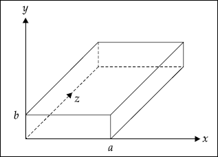
Fig. 6.5 A rectangular waveguide
Transverse Magnetic (TM) Waves in Rectangular Waveguide
TM waves are EM waves for which there is no component of H in the direction of propagation, that is, Hz = 0.
The wave equations given by Equation (6.34) can be easily solved using the method of product solution. In this method, two ordinary differential equations with known solutions are obtained. We know that,
If
where X is only a function of x and Y is only a function of y.
From Equations (6.34) and (6.35), we can write
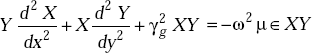
or,
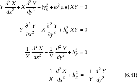
This expression equates a function of x to another function of y. This is possible when each of these functions is equal to some constant. Let the constant be B
and
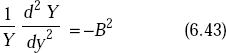
The general solution of these equations are
|
X = A1 cos Cx + A2 sin Cx |
|
|
and |
Y = A3 cos By + A4 sin By |
![]() = XY
= XY
= A1A3 cosCx cos By + A1 A4 cos Cx sin By
+ A2 A3 sin Cx cos By + A2 A4 sin Cx sin By
The constants A1, A2, A3, A4 are evaluated using the boundary conditions. Using the boundary condition
![]() = 0 at x = 0
= 0 at x = 0
![]() = A1 A3 cos By + A1A4 sin By
= A1 A3 cos By + A1A4 sin By
This is zero if A1 = 0
At y = 0, Equation (6.44) becomes
For this to vanish, A2 or A3 can be zero, while assuming C ≠ 0. Keeping A2 = 0 in Equation (6.44), ![]() becomes zero. Hence instead of A2 = 0 assume A3 = 0. Then Equation (6.44) becomes
becomes zero. Hence instead of A2 = 0 assume A3 = 0. Then Equation (6.44) becomes
![]() = A2 A4 sin Cx sin By
= A2 A4 sin Cx sin By
= K sin Cx sin By
[K = A2 A4]
At x = a
![]() = K sin Ca sin By
= K sin Ca sin By
For this to vanish for all values of y (assuming B ≠ 0) the constant C must be
At y = b,
For this to vanish for all values of x, B must be
Hence, the final expression for ![]() is
is
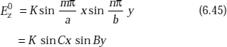
From Equations (6.44) and (6.45), we get
where ![]()
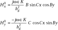
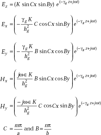
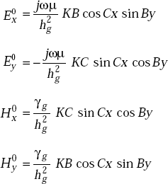
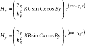
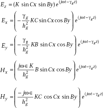
Therefore, the field components for a TM wave are:
TMmn wavefield components
Field variations of TM11 mode/wave are shown in Fig. 6.6.
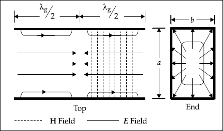
Fig. 6.6 Field variations of TM11 wave in hollow rectangular waveguide
Transverse Electric Waves
TE waves are EM waves for which there is no component of E in the direction of propagation, that is, Ez = 0.
The expressions for TE waves are derived in the same manner as in the case of TM waves. From Equation (6.39), we have
But Ez = 0
Hence, 
The first boundary condition is
that is, ![]()
But
![]() = (A1 cos Cx + A2 sin Cx).(A3 cos By + A4 sin By)
= (A1 cos Cx + A2 sin Cx).(A3 cos By + A4 sin By)
![]() = (A1 cos Cx + A2 sin Cx).(−A3 B sin By + A4 B cos By)
= (A1 cos Cx + A2 sin Cx).(−A3 B sin By + A4 B cos By)
As 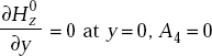
The secondary boundary condition is Ex = 0 at y = b
A is ![]()
B should be ![]()
Moreover, ![]()
and ![]()
Substituting Equation (6.47) in Equation (6.39), we get
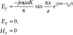
The field expressions for TE waves in complete form are
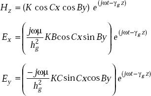
where
As TE10 is popular, its field equations are
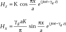
The field patterns are shown in Fig. 6.7.
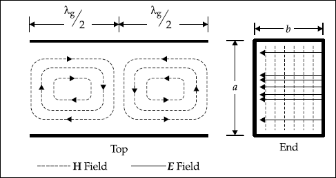
Fig. 6.7 Field patterns of TE10 mode
6.14 PROPAGATION PARAMETERS OF TE AND TM WAVES IN RECTANGULAR WAVEGUIDES
|
|
|
|
|
|
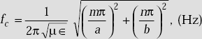
If
If
If
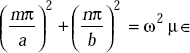
This particular ω corresponds to ωc, the angular cut-off frequency.
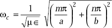
or,
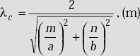
And cut-off wavelength is
The velocity of wave propagation is
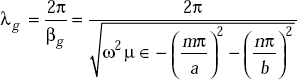
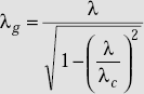
Derivation of guide wavelength in terms of free space and cut-off wavelengths
The expression for guide wavelength is
As
But
or,
The summary of propagation parameters of TE and TM waves are:
Dominant wave/mode It is defined as a wave which has the lowest cut-off frequency. This is represented by TE10.
In TEmn or TMmn waves, m represents the number of half-period variations of the field along x-axis and n represents the number of half-period variations of the field along y-axis. Here, the broad wall is along the x-axis and the narrow wall is along the y-axis.
Propagation and field equation of dominant mode, TE10
- Cut-off frequency for dominant mode, TE10
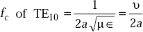
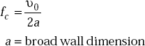
- Cut-off wavelength for dominant mode, TE10
λc of TE10 = 2a
Here |
λc = cut-off wavelength (m) |
|
a = broad wall dimension (m) |
|
m, n = integers = 1,2,3, … |
Transverse Electromagnetic Waves
In TEM wave, both E and H are entirely transverse to the direction of propagation, that is, if the direction of propagation is along z, Ez = 0, and Hz = 0.
TEM wave is called principal wave. Its cut-off frequency is zero and it exists in two conductor transmission lines or in free space.
Characteristics of TEM waves
TEM = TM00T
For TEM, Ez = 0, Hz = 0
Its cut-off frequency, fc = 0
It exists only in two conductor transmission lines or in free space.
It does not exist in hollow waveguides.
λg = λ
βg = β
α = 0
η = η0
λc = ∞
6.15 TEM WAVE DOES NOT EXIST IN HOLLOW WAVEGUIDES
Proof Method 1 Consider TM wavefield equations given by
As TEM = TM00, that is, when m = 0, n = 0, all the above field components vanish. This itself indicates that there exists no TEM waves in hollow waveguides.
Method 2 Assume that TEM wave exists within a hollow waveguide. Then, the magnetic field lines must be in the transverse plane. Also we know that
or,
This requires that the lines of H be closed loops. Hence, if a TEM wave exists (by hypothesis) inside the waveguide, the lines of H are closed loops in a plane perpendicular to the axis of the guide. It may be noted that the direction of propagation is along the axis.
By Maxwell’s first equation, we have
that is, the magnetomotive force around the closed loop of H lines is equal to the sum of axial displacement and conduction currents. As the space inside the guide is air or free space,
[as σ = 0]
that is, conduction current is zero. Hence the axial current must be a displacement current. If there exists displacement current in the axial direction which is the direction of propagation of EM energy, there should be a component of E ![]() in the axial direction. The presence of E along the axial or direction of propagation indicates the absence of TEM wave. Therefore, we conclude that there exists no TEM in hollow waveguides of any shape.
in the axial direction. The presence of E along the axial or direction of propagation indicates the absence of TEM wave. Therefore, we conclude that there exists no TEM in hollow waveguides of any shape.
6.16 EXCITATION METHODS FOR DIFFERENT TE AND TM WAVES/MODES
The excitation of TE10 by a probe is shown in Fig. 6.8.
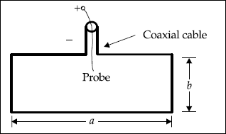
Fig. 6.8 Excitation of TE10 by a probe
The excitation of TE10 by a loop is shown in Fig. 6.9.
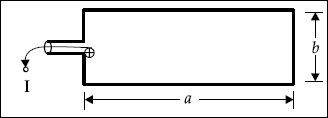
Fig. 6.9 Excitation of TE10 by a loop
The excitation method of TM11 by a probe and a loop are shown in Figs. 6.10 and 6.11.
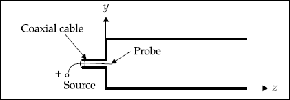
Fig. 6.10 Excitation method of TM11 by a probe
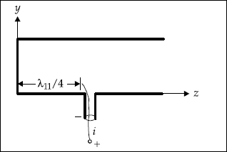
Fig. 6.11 Excitation method of TM11 by a loop
6.17 EVANESCENT WAVE OR MODE
This is defined as a wave TEmn or TMmn in which the operating frequency is less than the cut-off frequency and wave propagation does not take place. For evanescent wave, the TMmn wave impedance is purely capacitive and this causes only reactive power or energy storage.
6.18 WAVE IMPEDANCE IN WAVEGUIDE
For TEmn wave, wave impedance is defined as
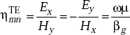
or,
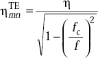
where η = intrinsic impedance of the unbounded medium.
The wave impedance is purely resistive and average power flow occurs in the waveguide when f > fc.
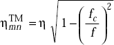
For non-propagating TMmn wave, the wave impedance
when f < fc for a particular TMmn mode.
The variation of magnitude of wave impedances of TEmn and TMmn for f < fc is shown in Fig. 6.12.
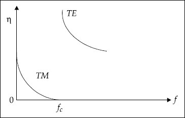
Fig. 6.12 Magnitude of TEmn and TMmn wave impedances (f < fc)
The wave impedance for the propagating modes is found to be
or,
From the above equations, we get
6.19 POWER TRANSMITTED IN A LOSSLESS WAVEGUIDE
The average power transmitted in z-direction is found by integration of the z component of the complex Poynting vector over a transverse cross-section of the waveguide, that is,
where H* = complex conjugate of H
Power transmission takes place through TE10 wave. Using the corresponding component values of E and H*, Pav is given by
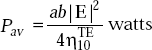
In an ideal guide, Pav is independent of z-direction.
Power Dissipation in a Lossy Waveguide
When the conductivity of the dielectric (σd) in the waveguide is non-zero and the conductivity (σc) of the walls is not infinite, wave in the propagating mode will be attenuated and the transmitted power will decrease exponentially with z.
The attenuation factor due to dielectric loss is the indication of power loss for TE10 mode, which is given by
The attenuation factor due to wall loss indicates power loss and is given by
where Ploss = power flow into the first 1m of the inner surface of the wall
and simplified expression for α w of TE10 mode is given by
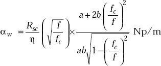
where RSC = surface resistance at cut-off frequency of TE10, Ω
![]()
The total attenuation factor is
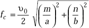
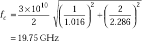
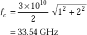
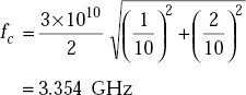
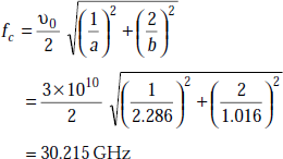
Problem 6.4 Find the cut-off frequencies for TE12 mode in a hollow rectangular waveguide whose dimensions are:
- a = 2.286 cm, b = 1.016 cm
- a = 1.016 cm, b = 2.286 cm
- a = 1 cm, b = 1 cm
- a = 10 cm, b = 10 cm
Solution The cut-off frequency for TE12 mode is given by
- a = 2.286 cm, b = 1.016 cm
- a = 1.016 cm, b = 2.286 cm
- a = 1 cm, b = 1 cm
- a = 10 cm, b = 10 cm
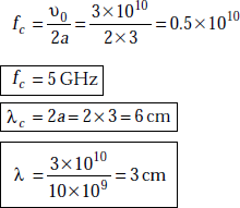
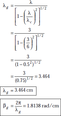
Problem 6.5 A rectangular waveguide with dimensions 3 × 2 cm operates at 10 GHz. Find fc, λc, λ, λg, βg, vp of TE10 mode.
Solution a = 3 cm, b = 2 cm, f = 10 GHz
For TE10 mode,
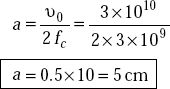
Problem 6.6 Find the broad wall dimension of a rectangular waveguide when the cut-off frequency for TE10 mode is (a) 3 GHz, (b) 30 GHz.
Solution
- fc = 3 GHz for TE10 mode
or,
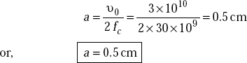
- fc = 30 GHz for TE10 mode
Problem 6.7 A hollow rectangular waveguide operates at f = 1 GHz and it has the dimensions of 5 × 2 cm. Check whether TE21 mode propagates or not.
Solution The propagation constant is given by
Here |
a = 5 cm = 0.05m |
|
b = 2 cm = 0.02m |
|
f = 1GHz = 109 Hz |
For TE21 |
m = 2, n = 1 |
|
μ0 = 4 π × 10−7 H/m |
|
∈0 = 8.854 × 10⁻¹² F/m |
γg for TE21 mode is |
|
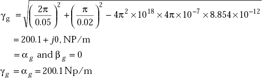
As γg is purely real, there is no propagation of TE21 mode.
6.20 WAVEGUIDE RESONATORS
A waveguide resonator is a resonator at high frequencies. It is made up of a rectangular waveguide with its open ends closed by shorts (Fig. 6.13).
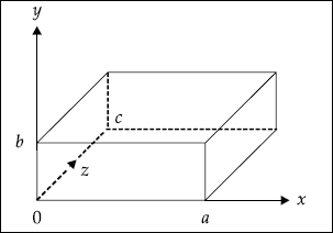
Fig. 6.13 Rectangular cavity
It is used for energy storage. As there is no propagation through the shorted ports, standing waves exist inside the cavity. These resonators are used for various applications, particularly in klystrons and wave metres.
Features of Resonators
A rectangular cavity (Fig. 6.13) is a rectangular waveguide whose open ends are shorted. In this type of structure, standing waves, TE and TM waves exist.
Resonators are mainly used for energy storage. At high frequencies RLC circuit elements are inefficient when used as resonators. This is because the dimensions of the circuits are of the order of operating wavelength. Because of this, radiation takes place which is undesirable.
The EM resonator cavities find extensive applications in klystron tubes, band pass filters, wave metres and microwave ovens.
TM Mode (Hz = 0)
If |
Ez = (x, y, z) = X(x) Y(y) Z(z), |
We can write, |
X(x) = C1 cos Ax + C2 sin Ax |
|
Y(y) = C3 cos By + C4 sin By |
|
Z(z) = C5 cos Cz + C6 sin Cz |
where
and
Here, we have three boundary conditions to solve the constants, C1, C2,…etc.
Ez = 0 at x = 0 and at x = a
Ez = 0 at y = 0 and at y = b
Ex = 0, Ey = 0 at z = 0 and at z = c
After simplification, Ezr becomes
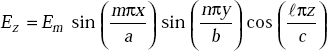
where Em = C2 C4 C5
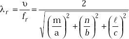
The resonant frequency is given by
or,
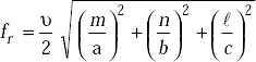
and
TE Mode (Ez = 0)
As in the case of TM mode, Hz is expressed
|
Hz (x, y, z) = X(x) Y(y) Z(z) |
where |
X(x) = p1 cos Bx + p2 sin Bx |
|
Y(y) = p3 cos Ay + p4 sin Ay |
|
Z(z) = p5 cos Cz + p6 sin Cz |
The set of boundary conditions are
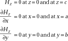
Using the boundary conditions, and simplifying, we get
where |
m = 0,1,2,3,… |
|
n = 0,1,2,3,… |
|
l = 0,1,2,3,… |
Dominant Mode
Dominant mode is defined as the mode which has the lowest resonant frequency for a given cavity size (a, b, c).
The waves are represented by TEmnl, TMmnl.
Degenerate Mode
Modes having the same resonant frequency are called degenerate modes. Ideally, the walls of the resonant cavity have infinite conductivity. But practically, cavity walls have finite conductivity. As a result, some stored energy is lost.
Quality Factor, Q
Quality factor is defined as
where |
ω = 2πf |
|
WL = average power loss in a cycle |
|
Wav = average stored energy |
Quality factor, for dominant mode, TE101 is
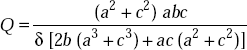
where δ = depth of penetration in cavity walls
6.21 SALIENT FEATURES OF CAVITY RESONATORS
- A completely closed metallic structure forms a cavity and it is called cavity resonator.
- It stores energy.
- TE and TM modes exist in the cavity.
- In TE mode, Ez = 0 (z is propagation direction) and Ex, Ey, Hx, Hy and Hz are present.
- In TM mode, Hz = 0 and Hx, Hy, Ex, Ey and Ez are present.
- In cavities, the electric and magnetic fields do not propagate along z-axis but they oscillate with time at a specified location.
- The lowest order of TMmnl mode is TM110.
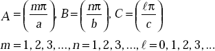
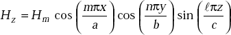
- The resonant frequency of the lowest order TM mode is
- The lowest order for TEmnl is TE101.
- The resonant frequency of the lowest order TE mode is
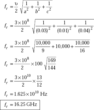
Problem 6.8 A copper rectangular cavity resonator is structured by 3 × 1 × 4 cm. Find its resonant frequency for TM110 mode.
Solution The dimensions of resonator are:
For TM110, the resonant frequency is
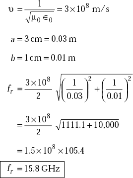
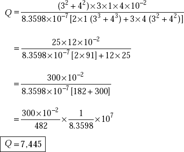
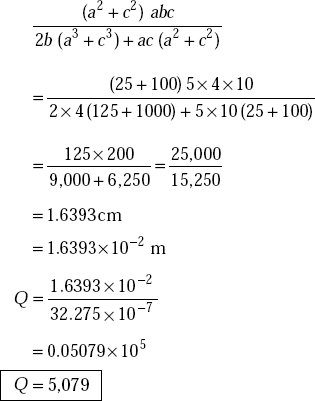
Problem 6.9 A copper walled rectangular cavity resonator is structured by 3 × 1 × 4 cm and operates at the dominant modes of TE and TM. Find its resonant frequency and quality factor. The conductivity of copper is 5.8 × 10⁷ mho/m. There is air inside the cavity.
Solution For TM mode, the dominant mode is TM100. Its resonant frequency is
Here
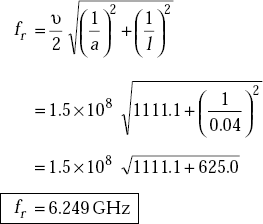
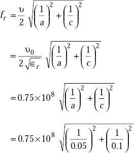
For TE mode, the resonant frequency of the dominant, TE101 is
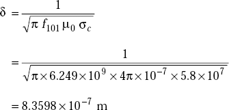
The quality factor, Q for TE101
where
Problem 6.10 A copper walled resonant cavity is dielectric (∈r = 4) filled and its dimensions are 5 × 4 × 10 cm. Determine the resonant frequency of TE101 and its quality factor.
Solution The conductivity of copper,
σc = 5.8 × 10⁷ mho/m
a = 5 cm
b = 4 cm
c = 10 cm
The resonant frequency of TE101 is
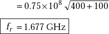
The quality factor, Q for this mode is
and
6.22 CIRCULAR WAVEGUIDES
The waveguides of circular cross-section (Fig. 6.14) are used to transmit EM waves from one point to another. Unlike rectangular waveguides, the circular waveguides do not have unique orientation as it is perfectly symmetrical around the axis.
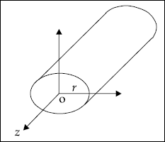
Fig. 6.14 Circular waveguide
6.23 SALIENT FEATURES OF CIRCULAR WAVEGUIDES
- It is easy to manufacture.
- They are used in rotational coupling.
- Rotation of polarisation exists and this can be overcome by rotating modes symmetrically.
- TM01 mode is preferred to TE01 as it requires a smaller diameter for the same cut-off wavelength.
- TE01 does not have practical application.
- For f > 10 GHz, TE01 has the lowest attenuation per unit length of the waveguide.
- The main disadvantage is that its cross-section is larger than that of a rectangular waveguide for carrying the same signal.
- The space occupied by circular waveguides is more than that of a rectangular waveguide.
- The determination of fields here consists of differential equations of certain type. Their solutions involve Bessel functions.
- Here also TE and TM modes exist.
For TM wave, the solution of axial component
Ez,nm = Jn (Kc r) (A cos nϕ + B sin ϕ)and for TE wave, it is
Hz,nm = Jn (Kc r) (A′ cos nϕ + B′ sin nϕ)
where |
Jn(Kc r) = Bessel function of the first kind |
|
r = the radius of the guide |
|
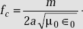
Kc = the cut-off wave number |
|
A, B, A′, B′ = constants |
The solutions for the Bessel function are obtained for certain values of Kc where these values of Kc are known as eigen values. If Kc is to produce solution of the Bessel function, (Kcr) must be the roots of the Bessel function. Then
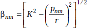
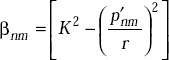
The propagation parameters for nmth mode TM waves are:
Phase constant,
|
|
|
|
|
|
where |
pnm = the roots of the Bessel function |
|
K = free space wave number = |
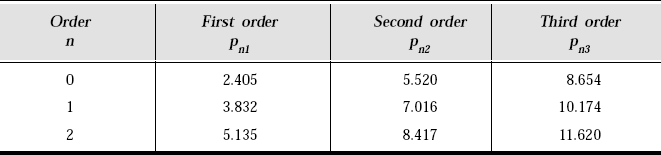
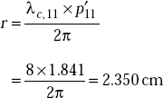
The cut-off wavelength for TM wave,
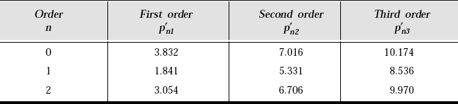
The roots of the Bessel function for TM mode are shown in Table 6.1.
Table 6.1 Roots of Bessel Function (TM Mode)
The roots of the Bessel function for TE mode are shown in Table 6.2.
Table 6.2 Roots of Bessel Function (TE Mode)
For circular waveguides, TE11 is the dominant mode. The propagation parameters for TEnm mode are:
where
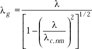
Guide wavelength,
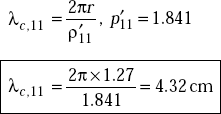
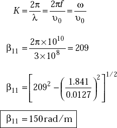
Problem 6.11 If the radius of a circular waveguide r = 1.27 cm, f = 10 GHz, find the cut-off wavelength for the dominant mode and phase constant. Assume that the waveguide is air-filled. Take p′11 = 1.841.
Solution For the dominant mode,
For TE11, we have
The phase constant,
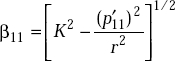
Here
Problem 6.12 Determine the size of the circular waveguide required to propagate TE11 mode if λc = 8 cm (ρ′11 = 1.841).
Solution We have ![]()
or,
Radius of the guide
POINTS/FORMULAE TO REMEMBER
- EM wave propagates in a waveguide with multiple reflections.
- TE and TM waves exist in a waveguide.
- TEM wave does not exist in a hollow waveguide.
- TEM wave exists between parallel plates.
- The dominant mode has the lowest cut-off frequency.
- The propagation constant between parallel plates is

- The cut-off frequency is a frequency below which the wave is attenuated completely.
- Between the parallel plates,
- λc for TE1 = 2a
- Group velocity, phase velocity and free space velocity are related by v20 =vp vg
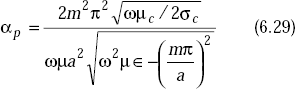
- Attenuation of TE waves between parallel plates is
- Attenuation of TE waves between parallel plates is
- A rectangular waveguide is used as a radiator, a high pass filter, a transmission line and feed element to an antenna.
- TEM = TM00
- For TEM, Ez = 0, Hz = 0
- λg =λ, βg =β, η = η0, α = 0 for TEM
- Typically, wave impedance for TEmn wave

- Circular waveguides can be used to produce circular polarisation. c TEM wave has zero cut-off frequency.
- The field components of TE wave between parallel plates are Ey, Hx, Hz.
- The field components of TM wave between parallel plates are Ex, Ez, Hy.
- TEM wave between parallel plates has only Ex and Hy components.
- The field components of TE in a hollow rectangular waveguide are Ex, Ey, Hx, Hy and Hz.
- The field components of TM in a hollow rectangular waveguide are Ex, Ey, Ez, Hx and Hy.
- The resonant frequency TE101 in a cavity resonator is
- The resonant frequency of TM110 in a cavity resonator is
OBJECTIVE QUESTIONS
Answers
1. Yes |
2. No |
3. Yes |
4. Yes |
5. Yes |
6. Yes |
7. Yes |
8. Yes |
9. Yes |
10. Yes |
11. Yes |
12. Yes |
13. Yes |
14. Yes |
15. Yes |
16. Yes |
17. No |
18. Yes |
19. Yes |
20. No |
21. No |
22. Yes |
23. Yes |
24. No |
25. Yes |
26. Yes |
27. Yes |
28. Yes |
29. Yes |
30. Yes |
31. Yes |
32. No |
33. No |
34. No |
35. No |
36. No |
37. Yes |
38. Yes |
39. Yes |
40. Yes |
41. Transverse electromagnetic wave
42. Transverse electric wave
43. Transverse magnetic wave
44. Zero
45. Zero
46. Zero
47. Infinity
48. Closing both ends of the waveguide with conducting plates
49.Lowest
50. ![]() is angular resonant frequency, Wav is the time-averaged stored energy (J) and Pd is the power dissipation
is angular resonant frequency, Wav is the time-averaged stored energy (J) and Pd is the power dissipation
51. αmn
52. Imaginary
53. A probe
54. Ex and Hy
55. Infinity
56. Nothing but discrete characteristic patterns
57. Copper or brass
58. Maxwell’s equations
59. No
60. Infinity
61. ![]()
62. Zero
63. Infinity
MULTIPLE CHOICE QUESTIONS
- When a wave is propagating in x-direction, TE wave has Ex equal to
- zero
- Ey
- Ez
- Ey + Ez
- For a wave propagating in z-direction in a hollow rectangular waveguide, TEM wave has
- Ez = o
- Hz = o
- all components of E and H are zero
- Ex = o, Hz = o
- The cut-off frequency of TEM wave is
- zero
- f
- infinity
- that of TE10
- If a = 2 cm, b = 1 cm for a waveguide, the cut-off frequency for TE10 mode is
- 0.75 GHz
- 7.5 GHz
- 1.5 GHz
- 1.5 MHz
- If the cut-off frequency for the dominant mode in a rectangular waveguide is 4 GHz, the dimension of the broad wall along x-axis is
- 4 cm
- 3.75 cm
- 5 cm
- 37.5 cm
- If f =10 GHz, the broad dimension of a rectangular waveguide, a = 2 cm, the cut-off frequency for TE10 is
- 0.75 GHz
- 7.5 GHz
- 10 GHz
- 5 GHz
- At f = 10 GHz, a = 2 cm, b = 1 cm, the cut-off frequency for TE01 is
- 10 GHz
- 1.5 GHz
- 15 GHz
- 7.5 GHz
- If in a rectangular waveguide the attenuation constant is 2 dB/m and the phase constant is 2 rad/m, the propagation constant is
- 2 + j2 dB/m
- 2 + j2 np/m
- 2 dB/m
- 2 np/m
- If β = 3oo rad/m for TE21 mode in a rectangular waveguide, the guide wavelength for TE21 is
- 0.209 cm
- 0.209 m
- 2.09 m
- 20.9 cm
- The cut-off frequency for TE10 is 5 GHz at an operating frequency of 6 GHz. The phase constant for TE10 is
- 69.5 rad/m
- 6.95 rad/m
- 0.833 rad/m
- 1.2 rad/m
- If the resonant frequency is 6 GHz, the time averaged stored energy is 10 Joules and the power dissipation is 20 watts in a resonator, the quality factor is
- 188.49
- 188.49 × 10⁹
- 200
- 188
- The ideal value of quality factor is
- ∞
- 0
- 100
- very small
- If
 , the intrinsic impedance is
- 122.47Ω
- 1.5Ω
- 0.333Ω
- 12.247Ω
- If the phase constant of TM21 is 320rad/m, α = 0 at an operating frequency of 10 GHz, the characteristic impedance of TM21 is
- 32Ω
- 539Ω
- 300Ω
- 53.9Ω
- The cut-off wavelength for the dominant mode in a rectangular waveguide having dimensions 4 × 3 cm is
- 12 cm
- 8 cm
- 1.33 cm
- 0.75 cm
- The cut-off wavelength for TE32 in a waveguide is 10 GHz. The guide wavelength for TE32 mode is
- 3 cm
- 3.2 cm
- 6 cm
- 3 m
- Skin depth in the copper wall of a waveguide operating at f = 6.25 GHz is
- 8.39 mm
- 83.9 mμ
- 83.9 mm
- 839 mm
- The mode of propagation in an air-filled waveguide of 2 × 1 cm dimensions operating at 10 GHz is
- TE01
- TE21
- TE10
- TE11
- If the propagation constant in a waveguide is 105+ j10, np/m the attenuation constant is
- 105 np/m
- 105 dB/m
- 10.5 np/m
- 115 np/m
- If γmn = αmn, in a waveguide
- propagation takes place
- no propagation takes place
- energy is increased
- energy is decreased
Answers
1. (a) |
2. (c) |
3. (a) |
4. (b) |
5. (b) |
6. (b) |
7. (c) |
8. (a) |
9. (b) |
10. (a) |
11. (b) |
12. (a) |
13. (a) |
14. (b) |
15. (b) |
16. (a) |
17. (b) |
18. (c) |
19. (a) |
20. (b) |
EXERCISE PROBLEMS
- A rectangular waveguide operates at 1 GHz and has dimensions of 5 × 2 cm. Find the distance from the source end at which the electric field of TE21 wave becomes 0.5% of its starting amplitude at z = 0. The amplitude of the electric field in z-direction at z =0 is 10kV/m.
- A rectangular waveguide with dimensions of 2.5 × 1.0 cm operates below 15.0 GHz. What are the TE modes that can be propagated if the waveguide is filled with material whose relative permittivity, ∈r = 4 and μr = 1, σ = 0? Find their cut-off frequencies and cut-off wavelengths.
- A hollow rectangular waveguide operates at 10 GHz. If the cut-off frequency of TM21 mode is 6 GHz, find its phase velocity, wavelength, phase constant.
- A hollow rectangular waveguide has the dimensions of a = 2.286 cm and b = 1.016 cm. Find the cut-off frequencies of TM11 and TM20.
- Find the cut-off wavelength of TE10 and TE20 mode in the hollow rectangular waveguide of dimensions a = 3 cm, b = 1.5 cm.
- In a hollow square waveguide, the cut-off frequency for TE10 mode is (a) 10 GHz (b) 20 GHz (c) 30 GHz. Find the dimensions of the waveguide.
- Find the radius of the circular waveguide required to propagate TE11 mode if λc = 10 cm. (ρ′11 = 1.84).
- Find the cut-off frequency of TE21 mode in a circular waveguide of radius 4 cm. (Take ρ′21 = 3.054).