Chapter 3
Steady Magnetic Fields
Steady magnetic fields are produced by steady currents.
The main objective of this chapter is to provide detailed concepts of magnetostatics. They include:
- applications of magnetostatic fields
- Faraday’s induction law, Biot-Savart law, Ampere’s circuit law, Ampere’s force laws for current elements
- force on current element and between current elements Lorentz force equation
- Boundary conditions, scalar and vector magnetic potentials
- fields in magnetic materials
- inductances
- energy stored in magnetic field and inductors
- comparison between electric and magnetic parameters/circuits
- points/formulae to remember, objective and multiple choice questions and exercise problems.
3.1 INTRODUCTION
Steady currents produce steady magnetic fields. Steady magnetic fields are magnetic fields which are constant with time. These fields are also called static magnetic fields or magnetostatic fields.
Magnetic fields have several applications. Some of them are listed below.
These fields are described by the magnetic field intensity, H and the magnetic flux density, B. These are related by B = μH. In fact, most of the relations in magnetostatics are derived from the knowledge of relations in electrostatics.
Steady magnetic fields are governed by Biot-Savart law and Ampere’s circuit law.
3.2 APPLICATIONS OF MAGNETOSTATIC FIELDS
Magnetostatic fields are used in
- magnetic separators
- particle accelerators like cyclotrons
- development of motors
- compasses
- microphones
- telephone ringers
- advertising displays
- velocity selector
- mass spectrometer
- transformers
- television focus controls
- high speed velocity devices
- magnetohydrodynamic generator
- electromagnetic pump and so on
3.3 FUNDAMENTALS OF STEADY MAGNETIC FIELDS
Steady magnetic fields are also called static magnetic fields or magnetostatic fields. These are produced by a magnet or by a current element. It is well known that loadstone is a natural magnet. But it is a fairly weak magnet. Strong magnets are made of iron, nickel, cobalt, or steel. The two opposite ends of a magnet are called its poles (Fig. 3.1).
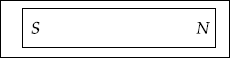
If a magnet is floated freely, one pole will point towards the north pole and is called the north pole of the magnet. The other pole is the south pole.
If a bar magnet is placed under a sheet of paper on which there are some iron fillings and then the paper is gently shaken, the fillings will tend to arrange themselves into a pattern like the one shown in Fig. 3.2.
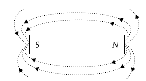
Fig. 3.2 Magnetic flux lines
It is observed that the iron fillings arrange themselves in a set of parallel lines going from one pole to another. These lines never cross or unite. These are called the magnetic lines of force or flux. The area covered by them is called the magnetic field. Flux lines move from N to S.
Electricity produces magnetism and magnets can produce electricity (Fig. 3.3).
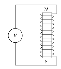
Fig. 3.3 Generation of electricity with a magnet
AC current can be produced by moving the magnet up and down in the coil or by rotating a conductor coil around a magnet. The latter method is preferred to produce large quantities of electric power.
3.4 FARADAY’S LAW OF INDUCTION
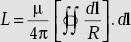
Faraday’s law of induction states that emf is induced whenever the magnetic flux linkage changes. In other words, an emf is induced in a conductor when the conductor cuts magnetic flux. The magnitude of the induced emf is equal to the rate of change of flux linkage, that is, mathematically,
Induced emf = ![]()
where |
V = induced emf (volt) |
|
N = number of turns |
|
ϕ = magnetic flux (wb) |
(−)ve sign indicates that the induced emf sets up a current in such a direction that the magnetic effect produced by it opposes the very cause producing it.
Magnetic flux It is defined as the lines of force produced in the medium surrounding electric currents or magnets. The flux through an area is measured from current flow in an electric circuit bounding the area when this circuit is removed from the magnetic field.
It is also defined as the surface integral of the magnetic flux density, that is,
3.5 MAGNETIC FLUX DENSITY, B (wb/m2)
B is defined as magnetic flux per unit area through a loop of small area. As ϕ depends on the orientation of the loop and its area, S is a vector. Its direction is normal to the plane of the loop.
or,
B is also defined as B = μH
where |
H |
= |
magnetic field (A/m) |
|
μ |
= |
permeability of the medium (H/m) |
|
|
= |
μ0 μr |
|
μ0 |
= |
permeability of free space = 4π×10−7H/m |
|
μr |
= |
relative permeability of the medium |
In this book, we are more interested to learn about the magnetic fields which are produced from current elements.
Definition of current element A current element is a conductor carrying current. It is represented by IL. Here I is the current and L is the length of the conductor.
Problem 3.1 If the magnetic flux density in a medium is given by ![]() what is the flux crossing the surface defined by
what is the flux crossing the surface defined by ![]() 0 ≤ z ≤ 2 m.
0 ≤ z ≤ 2 m.
Solution ![]()
By definition ![]()
where
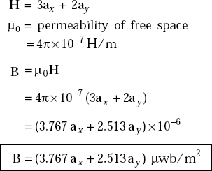
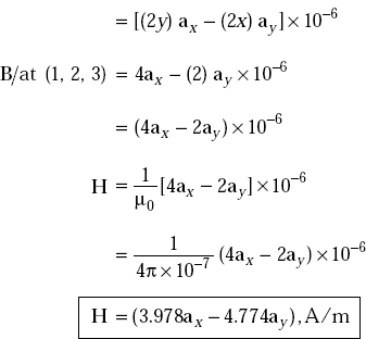
Problem 3.2 If a magnetic field, H = 3ax + 2ay, A/m exists at a point in free space, what is the magnetic flux density at the point?
Solution
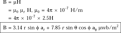
Problem 3.3 If the magnetic field, H = r sin ϕ ar + 2.5r sin θ cos ϕ aϕ, A/m exists in a medium whose μr = 3.0, find the magnetic flux density.
Solution H = r sin ϕ ar + 2.5 r sin θ cos ϕ aϕ, A/m
Relative permeability of the medium,
The magnetic flux density,
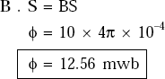
Problem 3.4 A circular coil of radius 2.0 cm is in a magnetic flux density of 10 wb/m2. If the plane of the coil is perpendicular to the field, determine the total flux around the coil.
Solution The flux density = 10 wb/m2
Area of the coil, |
S |
= |
πr2 |
|
|
= |
π × (2.0 × 10⁻²)2 |
|
|
= |
4π × 10−4 |
Total flux, |
ϕ |
= |
B · S |
As B and S are in the same direction,
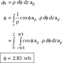
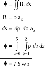
Problem 3.5 Given magnetic flux density, B = ρ aϕ, find the total flux crossing the surface ϕ = π/2, 1 ≤ ρ ≤ 2 m and 0 ≤ z ≤ 5 m.
Solution
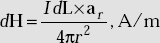
3.6 AMPERE’S LAW FOR CURRENT ELEMENT OR BIOT-SAVART LAW
Mathematically, Biot-Savart law is given by
Here |
dH |
= |
magnetic field at a point, P |
|
IdL |
= |
differential current element (A-m) |
|
ar |
= |
unit vector along the line joining the point P and the IdL |
|
r |
= |
distance of P from the current element (m) |
Statement of Biot-Savart law When a differential current element produces a differential magnetic field, dH, the field magnitude at a point is proportional to the product of IdL and sine of the angle between the conductor and the line of the point to the conductor. It is also inversely proportional to the square of the distance from the element to the point.
The direction of dH is normal to the plane containing IdL and the unit vector along the line from the element to the point. This normal is in the direction of progress of a right-handed screw turned from dL through a small angle to the line from the element to the point. The constant of proportionality is ![]()
The direction of the magnetic field is easily known using the right hand thumb rule. The magnetic field is in closed loops around the current element.
If a current element is held in the right hand with the thumb pointing upwards indicating the direction of current, then the direction of the remaining fingers indicate the direction of the magnetic field (Fig. 3.4), that is, if the current is upwards, the direction of magnetic field is anti-clockwise and if the current is downwards, the direction of magnetic field is clockwise.
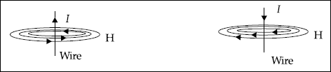
Fig. 3.4 Direction of H
3.7 FIELD DUE TO INFINITELY LONG CURRENT ELEMENT
The field produced by an infinitely long current element at a point is given by
I |
= |
current in the element |
|
|
ρ |
= |
distance of the point from the element |
Proof Assume an infinitely long current element to be vertical with the current passing upwards. Then, the direction of H is along aϕ (Fig. 3.5).
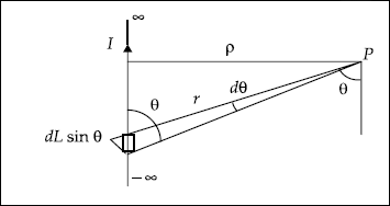
Fig. 3.5 Infinitely long current element
Let ρ be the distance of P from the element. Consider a differential element dL at a distance of r from P. Let the line joining P and IdL make an angle θ with the element. Now, by Biot-Savart law we have
dH due to IdL at P,
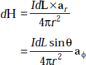
But dL sin θ = r d θ
As
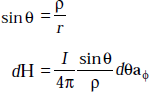
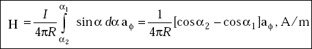
So H due to infinitely long current element is given by
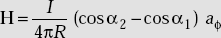
3.8 FIELD DUE TO A FINITE CURRENT ELEMENT
The magnetic field, H at a point, P due to a finite current element is
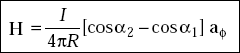
where |
I |
= |
current in the element |
|
R |
= |
distance of the point from the element axis |
|
α1 |
= |
angle made by the line joining the point and one end of the element with the axis of the element |
|
α2 |
= |
angle made by the line joining the point and the other end of the element with the axis |
Proof Consider Fig. 3.6.
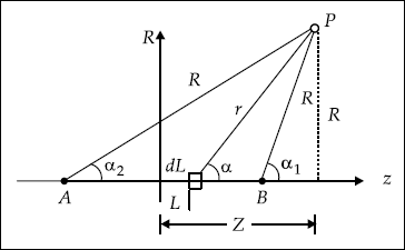
Fig. 3.6 Finite current element
The differential magnetic field, dH at the point P due to IdL (Fig. 3.6) is
|
|
|
|
We have |
r2 = (Z − L)2 + R2 |
and |
Z − L = R cot α |
Thus, we get |
−dL = −R cosec2 α dα |
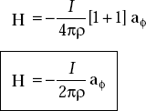
Problem 3.6 A thin conductor of finite length is along z-axis lying between z = Z1 and z = z2. Find H at a point P in the xy-plane. What is H if z1 = ∞ and Z2 = −∞ ?
Solution Consider Fig. 3.7 in which a differential current element IdL is shown on the current element.
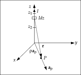
Fig. 3.7
Then, r
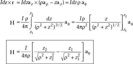
If z1 →∞, z2 →∞, H will be
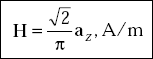
Problem 3.7 Determine the magnetic field intensity, H at the centre of a square current element. The length of each side is 2 m and the current, I = 1.0 Amp.
Solution Consider Fig. 3.8 and let each side be of length 2l.
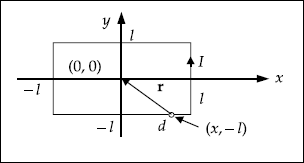
Fig. 3.8 Square current element
For the differential length, dx, we have

The total field at the origin is
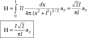
If 2l = 2 m or l = 1 m and I = 1 Amp,
3.9 AMPERE’S WORK LAW OR AMPERE’S CIRCUIT LAW
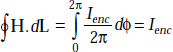
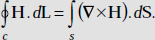
Statement: Ampere’s circuit law states that the line integral of the magnetic field H about any closed loop is equal to the current enclosed by the path. Mathematically,
Proof Consider a circular loop as in Fig. 3.9 which encloses a current element. Let the current be in the upward direction. Then, the field is anticlockwise (aϕ).
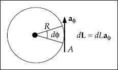
Fig. 3.9 Magnetic field around a current element
H at the point A is given by
Taking dot product with dL on both sides, we get
But
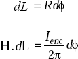
Taking line integral around the closed loop, we get
This is called the integral form of Ampere’s circuit law.
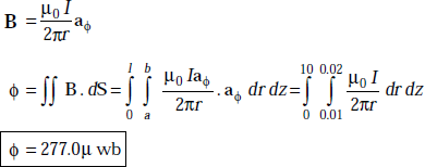
Problem 3.8 Determine the magnetic flux between the conductors of a coaxial cable of length 10 m. The radius of the inner conductor is a = 1 cm and that of the outer conductor is 2 cm. The current enclosed is 2A.
Solution By Ampere’s circuit law
that is, HL = I
Here, dL = 2πr, r lies between a and b.
or,
3.10 DIFFERENTIAL FORM OF AMPERE’S CIRCUIT LAW
The differential form of Ampere’s circuit law is given by
|
∇ × H |
= |
J |
|
J |
= |
conduction current density (A/m2) |
Proof Consider a closed rectangular path in x-y plane which encloses a current in z-direction (Fig. 3.10).
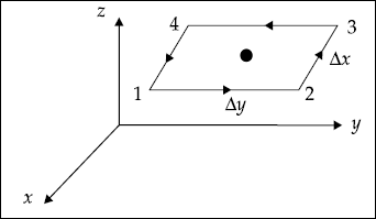
Fig. 3.10 Closed path in x-y plane enclosing a current element
Assume that H at the centre of the loop is known, that is,
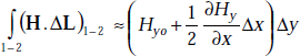
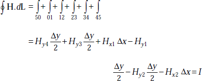
Line integral of H around the loop is the sum of H.dL on each side. Let us choose the direction of the loop to be 1-2-3-4. This corresponds to a current in the centre along z-direction, that is, we have
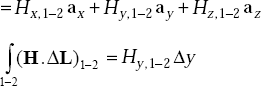
But by Taylor’s theorem, Hy, 1−2 can be obtained approximately by considering the first two terms, that is,
Thus
Second term on the right side
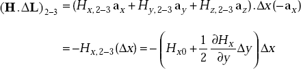
Similarly, third and fourth terms are given by
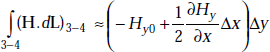
and
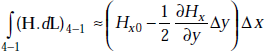
Therefore,
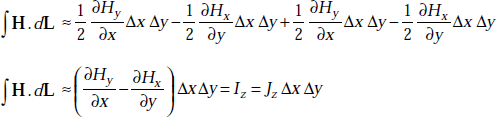
or,
If the closed path is made to shrink, this expression becomes exact, that is,
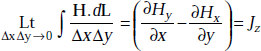
or,
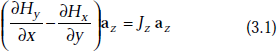
Similarly, if we choose closed paths oriented perpendicular to the remaining two coordinate axes, and by following exactly the above procedure, we get the expressions for the x and y components of the current density. These are
or,
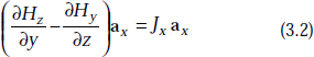
and
or,
3.1 + 3.2 + 3.3 gives
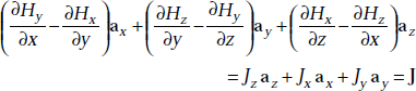
where J = Jx ax + Jy ay + Jz az (3.4)
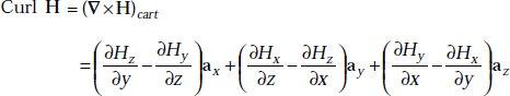
Left side of Equation (3.4) is nothing but curl of vector H,
that is,
This is the differential form of Ampere’s circuit law.
It is important to note the following.
 depends only on the boundary line and it does not depend on the particular surface used.
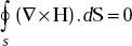 for any closed surface. This is because the boundary line shrinks to a point like the mouth of a balloon.
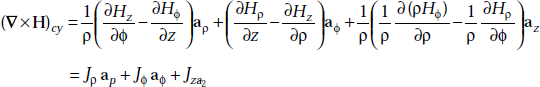
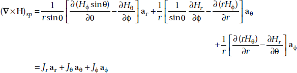
Ampere’s circuit law in different coordinate systems is
Problem 3.9 If H is given by H = y cos 2x ax + (y + ex) az, determine J at the origin.
Solution The differential form of Ampere’s circuit law is
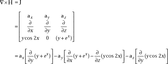
|
J |
= |
ax − ex ay − cos 2X az |
At |
(0, 0, 0) J |
= |
(ax − ay − az) A/m2 |
Problem 3.10 What is the magnetic field, H in Cartesian coordinates due to z-directed current element? Find J if I = 2 A.
Solution We have
But
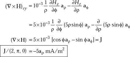
Problem 3.11 Determine J at (2, π, 0) in cylindrical coordinates if the magnetic field, H is given by H = 5ρ sin ϕ az, mA/m2.
Solution In cylindrical coordinates, we have
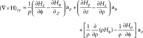
So
Problem 3.12 If the magnetic field, H = 100 sinθaθ A/m in spherical coordinates, determine J at ![]()
Solution
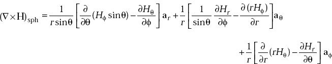
But in the present problem,
that is,
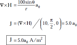
Problem 3.13 An infinitely long current element on x-axis carries a current of 1.0 mA in ax direction. Determine H at the point P (5, 2, 1).
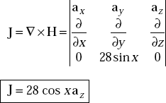
Problem 3.14 What is the current density which produces a magnetic field of H = 28 sin x ay ?
Solution By Ampere’s circuit law, the current density, J is
3.11 STOKE’S THEOREM
Stoke’s theorem relates a line integral to the surface integral and vice-versa, that is,
3.12 FORCE ON A MOVING CHARGE DUE TO ELECTRIC AND MAGNETIC FIELDS
If there is a charge or a moving charge, Q in an electric field, E, there exists a force on the charge. This force is given by
If a charge, Q moving with a velocity, V is placed in a magnetic field, B(=μH), then there exists a force on the charge (Fig. 3.11). This force is given by
FH |
= |
Q (V × B) |
B |
= |
magnetic flux density, (wb/m2) |
V |
= |
velocity of the charge, m/s |
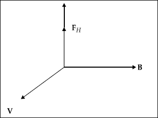
Fig. 3.11 Direction of field, velocity and force
If the charge, Q is placed in both electric and magnetic fields, then the force on the charge is
This equation is known as Lorentz force equation.
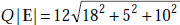
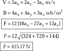
Problem 3.15 A charge of 12 C has velocity of 5ax + 2ay − 3az m/s. Determine F on the charge in the field of (a) E = 18ax + 5ay + 10a zV/m (b) B = 4ax + 4ay + 3az wb/m2.
Solution
- The force, F on the charge, Q due to E is
F
=
QE = 12 (18ax + 5ay + 10az)
=
216ax + 60ay + 120az
or,
F
=
F
=
254.27 N
- The force F on the charge due to B is
F = Q [V × B]
Here,
Problem 3.16 An electron has a velocity of 1 km/s along ax in a magnetic field whose magnetic flux density is B = 0.2ax − 0.3ay + 0.5az wb/m2.
- Determine the electric field intensity if no force is applied to the electron.
- Also find the force on the electron under the influence of both E and B when E = (ax + ay + az) KV/m.
Solution The expression for force F due to E and B is
- If F = 0,
Q [E + V × B] = 0
or,
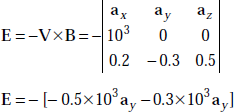
or,
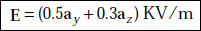
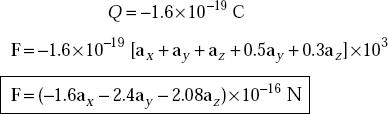
- The force on the electron due to E and B is
F = Q [E + V × B]
The charge of the electron,
3.13 APPLICATIONS OF LORENTZ FORCE EQUATION
The solution of Lorentz force equation is extremely useful to determine:
Electron orbits in magnetrons.
Proton paths in cyclotrons.
Plasma characteristics in Magneto Hydro Dynamic Generator (MHDG).
Motional characteristics of a charged body in combined electric and magnetic fields.
3.14 FORCE ON A CURRENT ELEMENT IN A MAGNETIC FIELD
The force on a current element when placed in a magnetic field, B is
or,
where θ is the angle between the direction of the current element and the direction of magnetic flux density
B |
= |
magnetic flux density, wb/m2 |
IL |
= |
current element, Amp-m |
Proof Consider a differential charge, dQ to be moving with a velocity, V in a magnetic field,  Then the differential force on the charge is given by
|
dF |
= |
dQ(V × B) |
But |
dQ |
= |
ρυ dυ |
|
dF |
= |
ρυ dυ ( |
|
|
= |
(ρυ V × B) dυ |
But |
ρυ V |
= |
J |
|
dF |
= |
J dυ × B |
J dυ is nothing but IdL,
|
dF |
= |
IdL × B |
or, |
F |
= |
IL × B, Newton |
Problem 3.17 A current element 4 cm long is along y-axis with a current of 10 mA flowing in y-direction. Determine the force on the current element due to the magnetic field if the magnetic field ![]()
Solution The force on a current element under the influence of magnetic field is
|
F |
= |
IL × B |
Here, |
IL |
= |
10 × 10−3 × 0.04ay |
|
|
= |
4 × 10⁻⁴ay |
|
|
|
|
|
B |
= |
5ax wb/m2 |
|
F |
= |
4 × 10−4ay × 5ax |
or |
F |
= |
(0.4ay × 5ax)×10−3 |
Problem 3.18 In a magnetic flux density of B = 1.0ax + 3.0ay wb/m2, a current element, 10az mA-m is placed. Find the force on the current element.
Solution The expression for force on a current element due to a magnetic field is given by
|
F |
= |
IL × B |
Here, |
IL |
= |
10az mA-m |
|
|
= |
10×10−3az, A-m |
|
B |
= |
(1.0ax + 3.0ay) wb/m2 |
|
F |
= |
10az × (1.0ax × 3.0ay)×10−3 |
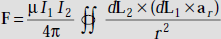
3.15 AMPERE’S FORCE LAW
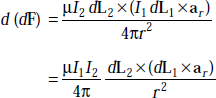
Ampere’s force law states that there exists a force between two current elements I1 dL1 and I2 dL2 and it is given by
μ |
= |
permeability of the medium in which the current elements are placed |
|
|
ar |
= |
distance between the elements |
|
ar |
= |
unit vector along the line joining the two current elements |
Proof Consider Fig. 3.12. Here, two differential current elements I1 dL1 and I2 dL2 are separated by a distance, r.
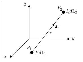
Fig. 3.12 Locations of differential current elements
Let the differential current element I1 dL1 be at point P1 and I2 dL2 be at point P2. The magnetic field at P2 due to I1 dL1 is given by
or,
This field exerts a force on the current element I2 dL2 at point P2 and it is given by
This is the differential of a differential force on a differential current element due to a differential field, dB. From the above two expressions we get,
3.16 BOUNDARY CONDITIONS ON H AND B
- The tangential component of magnetic field, H is continuous across any boundary except at the surface of a perfect conductor, that is,
Htan1 − Htan2 = Js
At non-conducting boundaries, Js = 0.
- The normal component of magnetic flux density, B is continuous across any discontinuity, that is,
Bn1 = Bn2
Proof Consider Fig. 3.13 in which a differential rectangular loop across a boundary separating medium 1 and medium 2 are shown.
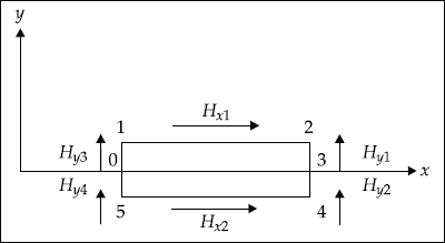
Fig. 3.13 A rectangular loop across a boundary
From Ampere’s circuit law, we have
As Δy → 0, we get
or,
Here, Hxl and Hx2 are tangential components in medium 1 and 2, respectively.
So, Htan1 − Htan2 = Js
Now consider a cylinder shown in Fig. 3.14.
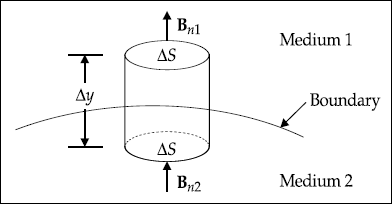
Fig. 3.14 A differential cylinder across the boundary
Gauss’s law for magnetic fields is
In this case, for ∆ y → 0
that is, Bn1 ΔS − Bn2 ΔS = 0
Therefore, ![]()
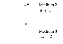
Problem 3.19 Two homogeneous, linear and isotropic media have an interface at x = 0. x < 0 describes medium 1 and x > 0 describes medium 2. μr1 = 2 and μr2 = 5 The magnetic field in medium 1 is
Determine:
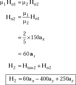
- Magnetic field in medium 2
- Magnetic flux density in medium 1
- Magnetic flux density in medium 2
Solution The magnetic field in medium 1 is
Consider Fig. 3.15.
-
H1
=
Htan1 + Hn1
Htan1
=
−400ay + 250az A/m
Hn1
=
150ax
The boundary condition is
Htan1
=
Htan2
Htan2
=
−400ay + 50az A/m
The boundary condition on B is

that is,
-
B1
=
μ1 H1
=
μ0 μr H1
=
4π × 10−7 × 2 (150ax − 400ay + 250az)
=
(376.5ax − 1004ay + 627.5az) μwb/m2
-
B2
=
μ2 H2
=
4π × 10−7 × 5 (60ax − 400ay + 250az)
=
(376.98ax − 2513.2ay + 1570.75az) μwb/m2
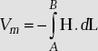
3.17 SCALAR MAGNETIC POTENTIAL
Like scalar electrostatic potential, it is possible to have scalar magnetic potential. It is defined in such a way that its negative gradient gives the magnetic field, that is,
Vm = scalar magnetic potential (Amp)
Taking curl on both sides, we get
But curl of the gradient of any scalar is always zero.
So, ∇ × H = 0
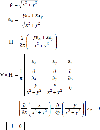
But by Ampere’s circuit law ∇ × H = J
or, J = 0
In other words, scalar magnetic potential exists in a region where J = 0.
The scalar potential satisfies Laplace’s equation, that is, we have
or, ∇2 Vm = 0 (J = 0)
Characteristics of Scalar Magnetic Potential (Vm)

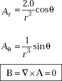
Problem 3.20 The magnetic field in a current free region is ![]() The region is defined by 1 ≤ ρ ≤ 2 m, 0 ≤ ϕ ≤ 2π and 0 ≤ z ≤ 2 m. Find the scalar magnetic potential at (4, 50°, 2).
The region is defined by 1 ≤ ρ ≤ 2 m, 0 ≤ ϕ ≤ 2π and 0 ≤ z ≤ 2 m. Find the scalar magnetic potential at (4, 50°, 2).
Solution We have
Here
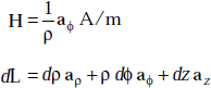
So,
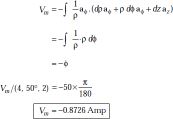
3.18 VECTOR MAGNETIC POTENTIAL
Vector magnetic potential exists in regions where J is present. It is defined in such a way that its curl gives the magnetic flux density, that is,
where A = vector magnetic potential (wb/m).
or, ![]() (K current sheet)
(K current sheet)
or, ![]()
Characteristics of Vector Magnetic Potential
It exists even when J is present.
It is defined in two ways
∇2A = −μ0 J
∇2 A = 0 if J = 0
Vector magnetic potential, A has applications to obtain radiation characteristics of antennas, apertures and also to obtain radiation leakage from transmission lines, waveguides and microwave ovens.
A is used to find near and far-fields of antennas.
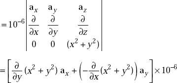
Problem 3.21 The vector magnetic potential, A due to a direct current in a conductor in free space is given by A = (x2 + y2) az μwb/m2. Determine the magnetic field produced by the current element at (1, 2, 3).
Solution A = (x2 + y2) az μwb/m2
We have B = ∇xA
Problem 3.22 When vector magnetic potential is given by
find the magnetic flux density.
Solution We have
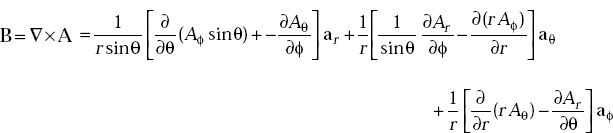
Here
3.19 FORCE AND TORQUE ON A LOOP OR COIL
Consider Fig. 3.16 in which a rectangular loop is placed under a uniform magnetic flux density, B.
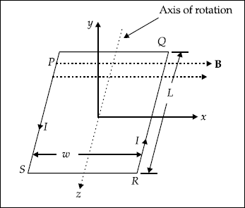
From Fig. 3.16, the force on QR due to B is
|
F1 |
= |
IL × B = −ILaz × Bax |
|
F1 |
= |
−ILBay |
that is, the force, F1 on QR moves it downwards. Now the force on PS
|
F2 |
= |
IL × B = −ILaz × Bax |
|
F2 |
= |
−ILBay |
Force, F2 on PS moves it upwards. It may be noted that the sides PQ and SR will not experience force as they are parallel to the field, B.
The forces on QR and PS exert a torque. This torque tends to rotate the coil about its axis.
The torque, T is nothing but a mechanical moment of force. The torque on the loop is defined as the vector product of moment arm and force,
that is,
where |
r |
= |
moment arm |
|
F |
= |
force |
Applying this definition to the loop considered above, the expression for torque is given by
or, T = −BISaz
where S = wL = area of the loop
The torque in terms of magnetic dipole moment, m is
where |
m |
= |
I1way |
|
|
= |
ISay |
Problem 3.23 A rectangular coil is placed in a field of B = (2a x + ay) wb/m2. The coil is in y-z plane and has dimensions of 2 m × 2 m. It carries a current of 1 A. Find the torque about the z-axis.
Solution |
m |
= |
IS an = 1x 4ax |
|
T |
= |
m × B = 4ax × (2ax + ay) |
|
T |
= |
4az, N-m |
Problem 3.24 Determine the torque on a square coil of 0.2 m × 0.2 m carrying a current of 3.0 A in a field of 10 wb/m2.
Solution |
T |
= |
BIS = 10 × 3 × 0.04 |
|
T |
= |
1.2 N-m. |
3.20 MATERIALS IN MAGNETIC FIELDS
A material is said to be magnetic if χm ≠ 0, μr ≠ 1.
A material is said to be non-magnetic if χm = 0, μr = 1.
The term ‘Magnetism’ is commonly discussed in terms of magnets with basic examples like north pole, compass needle, horse shoe magnets and so on.
Magnetic properties are described in terms of magnetic susceptibility and relative permeability of the materials.
Magnetic materials are classified into
- Diamagnetic materials
- Paramagnetic materials
- Ferromagnetic materials
Diamagnetic Materials
A material is said to diamagnetic if its electric susceptibility, χm < 0 and μr ≤ 1.0.
Examples are copper, lead, silicon, diamond and bismuth.
Characteristics of diamagnetic materials
- Magnetic fields due to the motion of orbiting electrons and spinning electrons cancel each other.
- Permanent magnetic moment of each atom is zero.
- These materials are widely affected by magnetic field.
- Magnetic susceptibility χm is (−)ve.
- μr = 1
- B = 0
- Most of the materials exhibit diamagnetism.
- They are linear magnetic materials.
- Diamagnetism is not temperature dependent.
- These materials acquire magnetisation opposite to H and hence they are called diamagnetic materials.
Paramagnetic Materials
A material for which χm > 0 and μr ≥ 1 is said to be paramagnetic.
Examples are air, tungsten, potassium and platinum.
Characteristics of paramagnetic materials
- They have non-zero permanent magnetic moment.
- Magnetic fields due to orbiting and spinning electrons do not cancel each other.
- Paramagnetism is temperature dependent.
- χm lies between 10−5 and 10−3.
- These are used in MASERS.
- χm > 0
- μr ≥ 1
- They are linear magnetic materials.
These materials acquire magnetisation parallel to H and hence they are called paramagnetic materials.
Ferromagnetic Materials
A material for which χm >> 0, μr >> 1 is said to be ferromagnetic.
Examples are iron, nickel, cobalt and their alloys.
Characteristics of ferromagnetic materials
- They exhibit large permanent dipole moment.
- χm >> 0
- μr >> 1
- They are strongly magnetised by magnetic field.
- They retain magnetism even if the magnetic field is removed.
- They lose their ferromagnetic properties when the temperature is raised.
- If a permanent magnet made of iron is heated above its curie temperature, 770°C, it loses its magnetisation completely.
- They are non-linear magnetic materials.
- B = μH does not hold good as m depends on B.
- In these materials, magnetisation is not determined by the field present. It depends on the magnetic history of the object.
3.21 MAGNETISATION IN MATERIALS
A material consists of atoms. The atoms in turn consist of electrons and nucleus. The electrons revolve in orbits around the nucleus and also rotate about their axes. The rotation about their axes is called spinning.
The phenomenon of orbiting and spinning of electrons produce an internal magnetic field. This field is similar to the field produced by a current loop.
The equivalent current loop exhibits a magnetic moment and the current loop is equivalent to a magnetic dipole. The magnetic moment is given by
|
m |
≡ |
Ib dS ≡ Ib dS an |
where |
an |
= |
unit normal to the plane of the loop |
|
Ib |
= |
bound current and is called as amperian produced by bound charges |
The dipole moments are arbitrarily oriented in a material and hence the net magnetic dipole moment is zero.
However, when such a material is kept in an external magnetic field, randomness disappears and dipole moments align themselves in the direction of the applied field. As a result, the net magnetic dipole moment is zero.
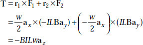
Now consider a bar magnet consisting of north and south poles. It is important to note that these poles, known as magnetic charges, cannot be isolated. They always appear in pairs. In a given material, they are randomly arranged.
Dipole moment is defined as
|
m |
≡ |
Qmd |
Qm |
= |
pole strength of magnet, A-m |
|
|
d |
= |
pole separation of magnet, m |
In fact, m is equivalent to the current loop given by
|
m |
= |
Ib dS |
So, |
m |
≡ |
Qm d = Ib dS, A-m2 |
A tiny bar magnet and a current loop are shown in Fig. 3.17.
Fig. 3.17 Bar magnet and current loop
Magnetic Dipole Moment, m
It is defined as
Here, the bound current, Ib is in a bound path enclosing a differential area, ds
If there are n magnetic dipoles per unit volume and if we consider a volume, ∆v, then total magnetic dipole moment is given by
Magnetisation, M Magnetisation, M is defined as the magnetic dipole per unit volume, that is, mathematically,
χm = magnetic susceptibility = (μr − 1).
Relation between the currents and the fields are
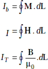
where |
IT |
= |
I + Ib |
or, |
I |
= |
IT − Ib |
that is,
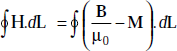
or,
The currents, in terms of current densities, are given by
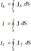
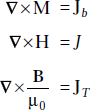
The relations in differential form are given by
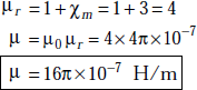
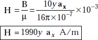
Problem 3.25 An isotropic material has a magnetic susceptibility of 3 and the magnetic flux density, B = 10y ax mwb/m2. Determine μr, μ, Jb J, M and H.
Solution The relation between relative permeability and magnetic susceptibility is
We have
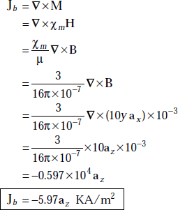
Now
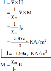
or, M = 5.97yax KA/m
and
Problem 3.26 A magnetic material has μr = 10/π and is in a magnetic field of strength, H = 5ρ3 aϕ A/m. Find the magnetisation.
Solution The magnetic flux density,
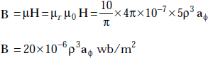
But |
B |
= |
μ0 (H + M) |
or, |
μ0 μr H |
= |
μ0 [H + M] |
or, |
M |
= |
H [μr − 1] |
3.22 INDUCTANCE
Inductor It is a coil of wire wound according to various designs with or without a core of magnetic material to concentrate the magnetic field.
Inductance, L In a conductor, device or circuit, an inductance is the inertial property caused by an induced reverse voltage that opposes the flow of current when a voltage is applied. It also opposes a sudden change in current that has been established.
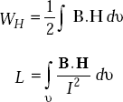
Definition of Inductance, L (Henry):
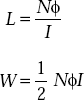
The inductance, L of a conductor system is defined as the ratio of magnetic flux linkage to the current producing the flux, that is,
Here |
N |
= |
number of turns |
|
ϕ |
= |
flux produced |
|
I |
= |
current in the coil |
where WH = energy in H produced by I.
In fact, a straight conductor carrying current has the property of inductance. Aircore coils are wound to provide a few pico henries to a few micro henries. These are used at IF and RF frequencies in tuning coils, interstage coupling coils and so on.
The requirements of such coils are:
- Stability of inductance under all operating conditions
- High ratio inductive reactance to effective loss resistance at the operating frequency
- Low self capacitance
- Small size and low cost
- Low temperature coefficient
3.23 STANDARD INDUCTANCE CONFIGURATIONS
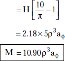
Toroid
It consists of a coil wound on annular core. One side of each turn of the coil is threaded through the ring to form a Toroid (Fig. 3.18).
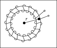
Fig. 3.18 Toroid
Inductance of Toroid, ![]()
Here |
N |
= |
number of turns |
|
r |
= |
average radius |
|
S |
= |
cross-sectional area |
I is the current in the coil.
Quality factor of the coil is
Specifications of inductors The specifications are:
Inductance value
Type of core
Type of winding, for example, single layer, multi-layer, standard and so on
Frequency
Q of the coil
Coupling factor
Self capacitance
Stability
Solenoid
It is a coil of wire which has a long axial length relative to its diameter. The coil is tubular in form. It is used to produce a known magnetic flux density along its axis.
A solenoid is also used to demonstrate electromagnetic induction. A bar of iron, which is free to move along the axis of the coil, is usually provided for this purpose. A typical solenoid is shown in Fig. 3.19.
Fig. 3.19 Solenoid
The inductance, L of a solenoid is
l = length of solenoid
S = cross-sectional area
N = number of turn
The magnetic field in a solenoid is
I is the current.
Coaxial Cable
It is a cable in which there are two concentric cylinders.
The inductance of a coaxial cable is
Here |
l |
= |
length of the cable |
|
b |
= |
outer radius |
|
a |
= |
inner radius |
The magnetic field, H in the cable is
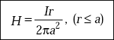
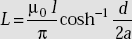
Parallel Conductors of Radius, a
The inductance of parallel conductors (Fig. 3.20) is
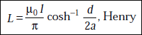
|
a |
= |
radius of the conductor |
|
d |
= |
distance between the conductors |
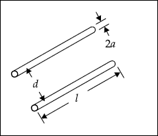
Fig. 3.20 Parallel conductors
It should be noted that the inductance, L depends on physical parameters but not on ϕ or I. L depends on permeability of the medium and a geometrical factor having the unit of length.
Problem 3.27 The radii of the inner and outer conductors of a coaxial cable are 2 mm and 6 mm respectively and μ = μ0. Find the inductance of a 10 m long cable.
Solution The inductance of a coaxial cable is
where |
l |
= |
length of the cable = 10 m |
|
r1 |
= |
radius of inner conductor = 2 mm |
|
r2 |
= |
radius of outer conductor = 6 mm |
|
|
|
|
|
L |
= |
2.2 μH |
Problem 3.28 A Toroid has air core and has a cross-sectional area of 10 mm It has 1000 turns and its mean radius is 10 mm. Find its inductance.
Solution The inductance of a Toroidal coil is given by
where
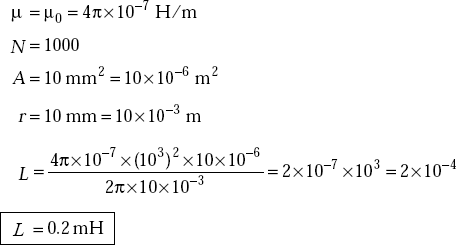
Problem 3.29 A solenoid has 400 turns with a length of 2 m. It has a circular cross-section of 0.1 m2. Find its inductance.
Solution The inductance of a solenoid is
Here
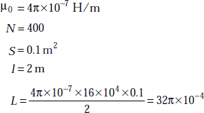
or, ![]()
3.24 ENERGY DENSITY IN A MAGNETIC FIELD
Energy density in a magnetic field,
Proof Method 1 (From fundamentals)
Faraday’ law of induction is
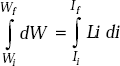
If the current is to be increased, the electric source must supply energy. The differential work done in a time, dt is
The total work done ![]()
For a linear magnetic circuit,
or, |
Ndϕ = Ldi |
|
dW = Li di |
If Wi is the initial energy in the coil corresponding to the initial current Ii and Wf is the final energy when the current is If, the increase of energy in the coil is
or,
If Ii = 0 and the current at any time t is I, the energy stored in the magnetic circuit is given by
For linear circuits,
We know that
and the total current enclosed by a path,
Here S is the cross-sectional area of the coil and l is its length.
So,
This represents the total energy stored. Therefore, the energy density is given by
or,
This is written in vector form as
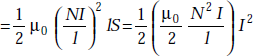
Method 2 The inductance of a solenoid is given by
|
|
where |
N = number of turns |
|
S = area of cross-section of a solenoid |
|
l = length of the solenoid |
The energy stored in an inductor is given by
Here lS = volume of space inside the coil.
But ![]() in a solenoid
in a solenoid
Energy stored ![]() Joules
Joules
or, Energy density, ![]() Hence proved.
Hence proved.
3.25 ENERGY STORED IN AN INDUCTOR
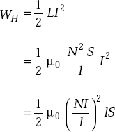
Energy stored in an inductor,
The energy density stored in a magnetic field is given as
|
|
But |
u = volume of space inside the coil = (lS), m3 |
|
|
|
N = number of turns |
|
I = current in the coil |
|
l = length of the coil |
So, energy stored
As the inductance of a solenoid is
The energy stored in an inductor is
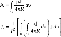
3.26 EXPRESSION FOR INDUCTANCE, L, IN TERMS OF FUNDAMENTAL PARAMETERS
The inductance, L, depends on physical parameters and medium but not on ϕ and I.
It is given by
Proof Self-inductance is defined as
But B = ∇ × A
A = vector magnetic potential
Standard vector identity is
∇ . (A × H) = H . (∇ × A) − A . (∇ × H)
or, H . (∇ × A) = ∇ . (A × H) + A.(∇ × H)
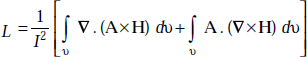
By divergence theorem,
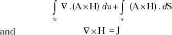
Now the expression for L becomes
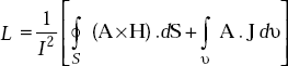
But the surface integral is zero as the surface encloses the volume containing all the magnetic energy and this requires A and H to be zero on the boundary surface, that is, the first term on the right = 0.
But
As Jdv is nothing but I dl, L becomes
3.27 MUTUAL INDUCTANCE
When the current in an inductor changes, flux varies and it cuts any other inductor nearby, producing induced voltage in both inductors.
The coil L1 of Fig. 3.21 is connected to a generator which produces varying current in the turns. In fact, the coil L2 is not connected physically to L1. But the turns are linked by the magnetic field. Hence a varying current in L1 induces voltage across L1 and also across L2.
When the induced voltage produces a current in L2, its varying magnetic field induces voltage in L1. Then the two coils L1 and L2 are said to have mutual inductance as the current in one produces voltage in the other.
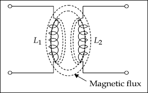
Fig. 3.21 Mutual inductance (M) between L1 and L2 due to flux linkage
Definition of Mutual Inductance
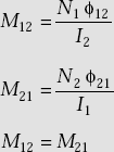
Mutual inductance, M between two coils is defined as the total flux linkage in one coil per unit change in current in the other coil. Mathematically, it is given by
It may be noted that
Coefficient of Coupling
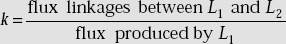
Coefficient of coupling between two coils is defined as the fraction of total flux from one coil linking another coil, that is,
k = coefficient of coupling ![]()
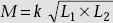
Calculation of Mutual Inductance, M
Mutual inductance increases with higher values of primary and secondary inductances and high coefficient of coupling.
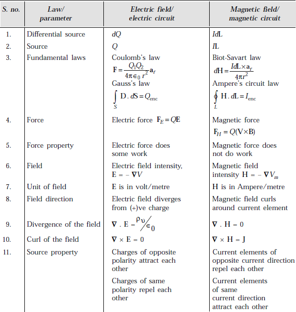
3.28 COMPARISON BETWEEN ELECTRIC AND MAGNETIC FIELDS/CIRCUITS/PARAMETERS
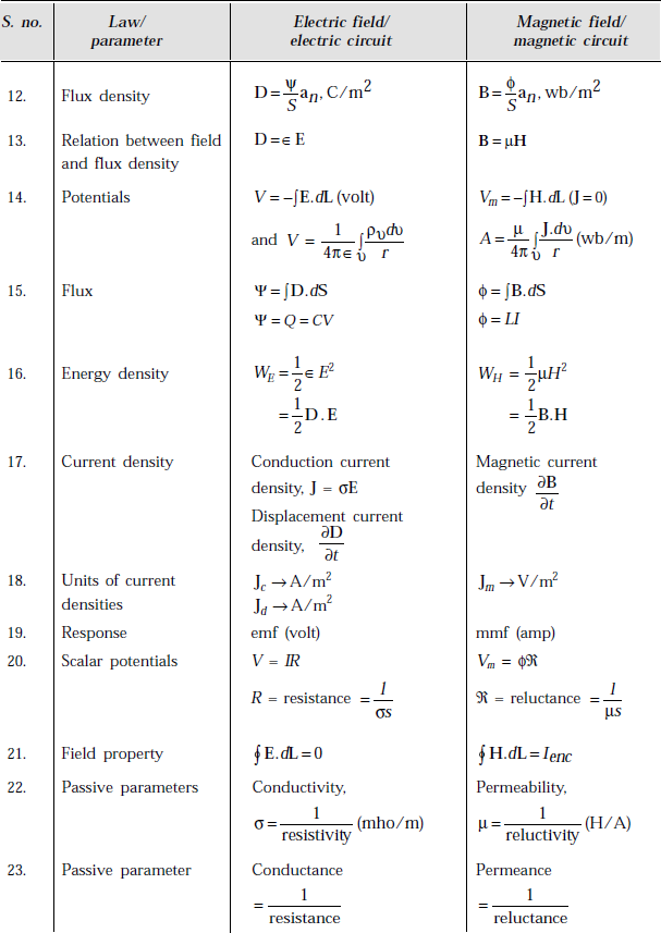
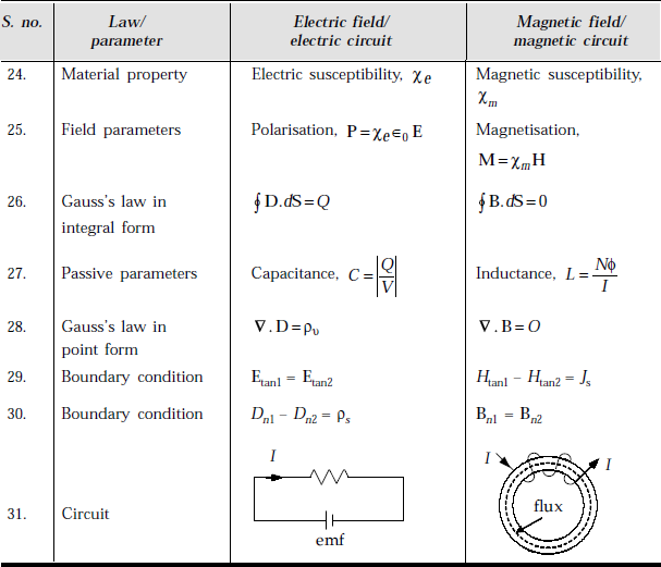
POINTS/FORMULAE TO REMEMBER
- Static magnetic fields are produced from current elements.
- There exists no isolated magnetic poles.
- Magnetic field lines are closed loops.
- Magnetic field and magnetic flux density are related by B = μH.
- Biot-Savart law is
 .
. - Magnetic field due to a vertically unpolarised infinitely long current element is
 .
. - Magnetic field due to a finite element is
 .
. - Ampere’s circuit law in differential form is ∇ × H = J.
- Ampere’s circuit law in integral form is
 .
. - Stoke’s theorem is
 .
. - Force on a charge due to electric field is FE = QE.
- Force on a moving charge due to magnetic field is FH = Q (V × B).
- Lorentz force equation is F = Q (E + V × B).
- Force on a current element in a magnetic field is F = IL × B.
- Ampere’s force law is
 .
. - Htan1 – Htan2 = Js
- Bn1 = Bn2
- Scalar magnetic potential is
 .
. - Scalar magnetic potential has the unit of Ampere.
- Vector magnetic potential is
 .
. - A has the unit of wb/m.
- The torque on the loop is T = r × F.
- For diamagnetic materials, χm < 0 and μr ≤ 1.0.
- For paramagnetic materials, χm > 0, μr ≥ 1.
- For ferromagnetic materials, χm >> 0, μr >> 1.
- Examples of diamagnetic materials are copper, lead, diamond, silicon, bismuth and so on.
- Examples of paramagnetic materials are air, tungsten, potassium, platinum and so on.
- Examples of ferromagnetic materials are iron, nickel, cobalt and their alloys.
- Magnetic dipole moment is m = Ib dS, Amp-m2.
- Magnetisation is M = χm H, A/m2.
- Magnetic susceptibility is χm = μr – 1.
- Magnetic flux density in magnetic materials is B = μ0 [H + M].
- Self inductance, L is defined as
 , Henry.
 - Inductance of a Toroid is
 .
. - Magnetic field in a Toroid is
 .
. - Quality factor of a coil is
 .
. - Inductance of a solenoid is
 .
. - Magnetic field in a solenoid is
 .
. - Inductance of a coaxial cable is
 .
. - The magnetic field in a coaxial cable is
 .
. - The inductance of parallel wires is
 .
. - Energy stored in a static magnetic field is
 .
. - Energy stored in an inductor is
 .
. - Inductance in terms of fundamental parameters is
- Mutual inductance between two coils is
- Coefficient of coupling is
 .
. - Mutual inductance is calculated from
 , Henry.
OBJECTIVE QUESTIONS
1. Static magnetic fields are produced from charges at rest. |
(Yes/No) |
2. South and north poles of a magnet can be isolated. |
(Yes/No) |
3. Magnetic field is not conservative. |
(Yes/No) |
4. Electricity produces magnetism. |
(Yes/No) |
5. Magnets produce electricity. |
(Yes/No) |
6. A steady current, J flowing in a wire generates a magnetic induction field, B. |
(Yes/No) |
7. A magnetic induction field, B does not produce a current, J. |
(Yes/No) |
8. Magnetic flux is conservative. |
(Yes/No) |
9. Magnetic charge means magnetic pole. |
(Yes/No) |
10. Magnetic flux density is a vector. |
(Yes/No) |
11. Scalar magnetic potential exists where J is present. |
(Yes/No) |
12. Torque is a vector. |
(Yes/No) |
13. Inductance depends on current and flux. |
(Yes/No) |
14. The value of inductance depends on physical parameters only. |
(Yes/No) |
15. |
|
16. |
|
17. H = ∇Vm |
(Yes/No) |
18. ∇2 Vm = ρυ |
(Yes/No) |
19. A = ∇ × B |
(Yes/No) |
20. H = ∇ × A |
(Yes/No) |
21. B = ∇ × A |
(Yes/No) |
22. M12 = M21 |
(Yes/No) |
23. Inductance of a solenoid is proportional to N2. |
(Yes/No) |
24. Inductance of a solenoid is proportional to the area of cross-section. |
(Yes/No) |
25. Inductance coil should have very low temperature coefficient. |
(Yes/No) |
26. ∇ × M = Jb |
(Yes/No) |
27. Magnetic field is measured by _____. |
|
28. SQUID means _____. |
|
29. The unit of magnetic flux is _____. |
|
30. The unit of magnetic flux density is _____. |
|
31. Ampere’s circuit law is _____. |
|
32. Biot-Savart law is _____. |
|
33. Differential form of Ampere’s circuit law is _____. |
|
34. Lorentz force equation is _____. |
|
35. The boundary condition on H is _____. |
|
36. The boundary condition on B is _____. |
|
37. The unit of scalar magnetic potential is _____. |
|
38. The unit of vector magnetic potential is _____. |
|
39. Magnetic dipole moment has the unit of _____. |
|
40. Magnetisation has the unit of _____. |
|
41. Energy stored in an inductor is _____. |
|
42. Energy stored in a magnetostatic field is _____. |
|
43. Torque is_____. |
|
44. The unit of torque is _____. |
|
45. Magnetisation is _____. |
|
46. Bound current is called _____. |
|
47. Quality factor of the coil is _____. |
|
48. Two specifications of an inductance are _____. |
|
49. Magnetic field in a solenoid is _____. |
|
50. Magnetic field in a Toroid is _____. |
|
Answers
1. No |
2. No |
3. Yes |
4. Yes |
5. Yes |
6. Yes |
7. Yes |
8. Yes |
9. Yes |
10. Yes |
11. No |
12. Yes |
13. No |
14. Yes |
15. Yes |
16. Yes |
17. No |
18. No |
19. No |
20. No |
21. Yes |
22. Yes |
23. Yes |
24. Yes |
25. Yes |
26. Yes |
27. SQUID |
|
28. Super Conducting Quantum Interference device
29. Weber
30. Wb/m2
31. ![]()
32. ![]()
33. ∇ × H = J
34. F = Q [E + V × B]
35. Htan1 – Htan2 = Js
36. Bn1 = Bn2
37. Ampere
38. Wb/m
39. Amp-m2
40. A/m
41. ![]()
42. ![]()
43. r × F
44. Newton-metre
45. χm H
46. Amperion current
47. ![]()
48. Inductance value, Q of the coil
49. ![]()
50. ![]()
MULTIPLE CHOICE QUESTIONS
- If flux density is 10 wb/m2 and the area of the coil is 2 m2, the flux is
- 10 wb
- 20 wb
- 5 wb
- 40 wb
- If the magnetic field, H = 4ax, A/m, flux density in free space is
- 1.6πaxμ wb/m2
- 16πax μ wb/m2
- 1.6πμ wb/m
- 160π ax wb/m
- If the curl of the magnetic field is 2.0ax A/m2, the current density is
- 2.0ax A/m2
- 1.0ax A/m2
- 2.0 A/m
- 1.0 A/m
 is
is
- zero
- Ienc
- J

- If a charge of 2.0 C is placed in an electric field of 2.0 V/m, the force on the charge is
- 4.0 N
- 1.0 N
- 2.0 N
- zero
- If a charge, 1.0 C is moving with a velocity 2.0ax in a magnetic field of B = 1.0ay, the force on the charge is
- 2.0az
- 1.0ay
- 2.0ax
- 1.0az
- The force produced by B = 2.0 wb/m2 on a current element of 2.0 A-m, is
- 4.0 N
- 1.0 N
- 2.0 N
- 0.5 N
- The magnetic field in an ideal conductor is
- zero
- infinite
- finite
- the same as its outside field
- If the normal component of B in medium 1 is 1.0ax wb/m , the normal component in medium 2 is
- 0.5ax wb/m2
- 1.0ax wb/m2
- 2.0ax wb/m2
- 1.0 wb/m2
- The unit of scalar magnetic potential is
- Ampere
- Volt
- Amp/m
- Volt/m
- ∇ × ∇ Vm is
- zero
- ∇2
- j
- ∇.∇Vm
- ∇ × A is
- H
- B
- j
- 0
- Torque has the unit of
- N-m
- N/m
- N-m2
- N
- Magnetisation, M is defined as
- χ m H
- χm μ0 H
- χm B
- B/μ0
- The unit of magnetic dipole moment is
- A-m
- A-m2
- A/m
- C-m
- The dipole moment of a magnet is
- Qm d
- Qm d
- Qm I
- Qm S
- If μ= 10μH/m for a medium, H = 2.0 A/m, the energy stored in the field is
- 0.5 J/m3
- 1.0 μJ/m3
- 2.0 μJ/m3
- 1.0 J/m3
- If a current of 1.0 amp flowing in an inductor, L = 2 Henry, the energy stored in an inductance is
- 2.0 J
- 1.0 J
- 2.0 J/m3
- 0.5 J
 is
is
- zero
- Q
- H
- J
- The unit of magnetic susceptibility is
- Nil
- Amp
- H/m
- Wb
Answers
1. (b) |
2. (a) |
3. (a) |
4. (a) |
5. (a) |
6. (a) |
7. (a) |
8. (a) |
9. (b) |
10. (a) |
11. (a) |
12. (b) |
13. (a) |
14. (a) |
15. (b) |
16. (a) |
17. (c) |
18. (b) |
19. (a) |
20. (a) |
- For a circular current element of radius, b = 2 m, determine the magnetic field H on the axis of the loop if I = 2A, h = 2 m. Also find H at the centre of the loop.
- Three thin conductors along x, y and z-axes carry a current of 1.0 mA. Determine the magnetic field, H at the point (2, 3, 4).
- What is the current that produces a magnetic field inside a conductor of circular cross-section given by
The radius of the conductor is 0.01 m. Assume K = 50.0π (m −1).
- If the separation between two infinitely long current elements is 5 m and the elements carry 2 Ampere in opposite direction, find the magnetic field at 1 m from one current element.
- The radius of a circular coil is 1.0 cm. The plane of the coil is perpendicular to a magnetic flux density of 10 mwb/m2. Determine the total flux threading the
- A charge of 2.0 C moving with a velocity of V = (ax + ay) m/s experiences no force in electric and magnetic fields. If the magnetic field intensity is
find the electric field.
- If the magnetic field is
 what is the force on a charge of 1.0 pc moving with a velocity of 106 ax m/s?
- A uniform magnetic flux density, B = 1.0 wb/m17 is present in a medium whose μ= 100μ0, as shown in the Fig. 3.22.
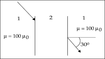
Fig. 3.22
If the air gap is cut as in the figure, determine B in the air gap.
- What is the inductance of a coaxial cable of length 10 m if r1 = 2 mm, r2 = 6 mm? Assume μr = l.
- What is the inductance of a pair of transmission lines separated by 1.868 m, if the diameter of each wire is 0.01 m and the medium between the lines has μ = 2 μ0 ? Length of the line is 10 m.