
Let's start with learning how to use sensors with Intel Galileo. In this section, we will develop an application with Intel Galileo. We pick the temperature and humidity sensors for application development because knowing the temperature of your house is the key to energy management. With temperature data, you can decide whether to switch on or switch off the heater or air conditioner in your home to save energy.
In order to get temperature data, we will use a new device: the Sensirion SHT11 Temperature and Humidity Sensor. We will connect this sensor to Intel Galileo's pinout to read temperature and relative humidity values. All the development will be done with the C programming language and Linux operating system, as mentioned earlier.
When we are finished with this section, you will have the knowledge to use pins on Intel Galileo and GPIO device files in the Linux filesystem. These methods can be reused for other sensors and devices in your future applications with them.
We have picked a sensor, that uses a data and clock line to enable measurement on sensors. There are many temperature sensors in the market that are compatible with Intel Galileo. LM35 is a widely used temperature sensor, and it provides a voltage output proportional to Centigrade temperatures. Our SHT11 sensor provides us with digital data as raw temperatures and provides the coefficients to convert the raw data to human- readable Centigrade temperatures.
The image shown here is a SHT11 sensor:
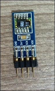
While working with sensors on Intel Galileo or any other platform, we need to first read the datasheet provided by the manufacturer to understand the working of the sensor and its operational limits.
Note
The datasheet for the SHT11 is accessible from the following link: http://www.sensirion.com/fileadmin/user_upload/customers/sensirion/Dokumente/Humidity/Sensirion_Humidity_SHT1x_Datasheet_V5.pdf
Understanding the critical information provided on datasheets is essential. As we have read in the sensor datasheet, SHT11 works with simple clock and data lines to read and write bits. It doesn't use any specific bus or protocol such as I2C, SPI, or UART, and so we will pick two GPIO pins from Intel Galileo to send and get bits to/from the SHT11 sensor.
To start reading from the sensor, we need to send a byte as a command to SHT11. Our application will send 0x03 bytes to SHT11 in order to measure temperature and 0x05 bytes to measure relative humidity; you can find the commands in the datasheet. Since the sensor is not using any communication bus, we will use GPIO pins to send and get data bit by bit. The figure given here shows how we send bits from a DAT pin.
The same method can be used to read from a DAT pin.

Before sending the command, there are a few steps that need to be carried out with clock data to tell the sensor about the incoming command. After sending the command, it is also required to complete some bit transfers and readings from the sensor to acknowledge that the command was received. The following figure shows the steps to read temperature data from the SHT11 sensor:

The last step is to wait for the sensor to make data pin low (0) to start reading bits from that. In order to complete the temperature measurement from the sensor, we need to complete all the steps described. For more details, you can follow up with the sensor datasheet.
Let's connect our sensor to Intel Galileo before coding. The SHT11 sensor has four pins to be connected: the VCC, GND, clock (SCK), and data (DAT) pins.
We will use 5V for VCC since it is operational with 5V and produces more accurate data. The GND Pin can easily be seen on the Intel Galileo pinout. For the clock and data, we picked two GPIO pins IO7 and IO8 to send 0 and 1 to the sensor. IO7 on the board will be the data line and IO8 will be the clock line of the SHT11 sensor.
The following figure basically represents the pin connections of SHT11 to the corresponding pinout on Intel Galileo.

We have connected SHT11 to Intel Galileo. Now we can start the development of our application to read environmental temperature and humidity values. As described in Chapter 1, Getting Started with Intel Galileo, let's create a new C project and name it as thermostat.c or thermometer.c. It will create a C file named after your project with a main function.
First, we need to include the following headers and define the constants as needed:
#include <stdlib.h>
#include <stdio.h>
#include <fcntl.h>
#include <stdint.h>
#define LSBFIRST 0
#define MSBFIRST 1
// Global Definitions for High/Low and Input/Output values for //GPIO Operations
#define HIGH 1
#define LOW 0
#define INPUT "in"
#define OUTPUT "out"
//Buffers needed for I/O Operations
#define BUF 8
#define MAX_BUF 256
// IO7 and IO8 pins Linux GPIO numbers to access from Linux
#define DATA_PIN 38  //IO 7
#define CLOCK_PIN 40 //IO 8
//SHT11 Commands Defined in Datasheed
const uint8_t measure_temperature = 0b00000011;
const uint8_t measure_humidity = 0b00000101;
const uint8_t read_status = 0b00000111;
const uint8_t write_status = 0b00000110;

//Temperature Measurement Constants as in Datasheet
// T =  d1 + d2 * SOt
const float D1_5V = -40.1;
const float D2_14bit = 0.01;
const float D2_12bit = 0.04;
//Relative Humidity Measurement Constants as in Datasheet
// RH = c1 + c2 * SOrh + c3 * SOrh * SOrh
const float C1 = -2.0468;
const float C2 = 0.0367;
const float C3 = -0.00395484;

//Global Variables to Store Temperature and Relative Humidity
float temperature = 0.0; //Celcius
float humidity = 0.0; //Relative Humidity
We will send bits by toggling GPIO pins and read bits from GPIO by setting the GPIO direction as the input. GPIO pins direction in the way it is working; if GPIO is defined as the output, it can send 0 or 1 to pinout; if it is defined as input, a low, or high signal coming to the pin can be read. In the Linux operating system, everything is a file, virtual or real, and so you can access virtual files to read and write data. Each pin on Intel Galileo has a corresponding device file on the Linux filesystem. Here you can find all corresponding numbers from the Intel Galileo I/O Mapping document. IO7 and IO8 are GPIO 38 and 40 respectively on the Linux filesystem.
Note
The Intel Galileo I/O Mapping document is available at http://www.intel.com/support/galileo/sb/CS-035205.htm
Let's continue with our main function. We will simply read the temperature at first like this:
int main(void) {
  read_temperature();
  printf("Temperature is %f Centigrade
", temperature);
  return 0;
}
void read_temperature(){
// Conversion coefficients from SHT11 datasheet
  const float D1 = -40.0;   // for 14 Bit @ 5V
  const float D2 = 0.01; // for 14 Bit DEGF
  send_command_SHT11(measure_temperature);
  wait_for_result();
  int raw = retreive_data_SHT11();
  skip_crc();
  temperature = 0.0;
  temperature = ((float) raw * D2) - D1;
}
The read_temperature function first sends a command to the SHT11 sensor bit by bit, waits for the sensor to take the data line to low and then retrieves the raw temperature value from the sensor. The first data read from the sensor is the raw value (in the datasheet, Celsius and Fahrenheit degree calculation equations and coefficients are given); finally we apply the equation and get the result.
Let's proceed to the send_command_SHT11 function:
int send_command_SHT11(int command) {
  int ack;
  //Start Transmission
  gpio_set_mode(DATA_PIN, OUTPUT);
  gpio_set_mode(CLOCK_PIN, OUTPUT);
  gpio_set_value(DATA_PIN, HIGH);
  gpio_set_value(CLOCK_PIN, HIGH);
  gpio_set_value(DATA_PIN, LOW);
  gpio_set_value(CLOCK_PIN, LOW);
  gpio_set_value(CLOCK_PIN, HIGH);
  gpio_set_value(DATA_PIN, HIGH);
  gpio_set_value(CLOCK_PIN, LOW);
  //Shift Out
  shiftOut(MSBFIRST, command);
  gpio_set_value(CLOCK_PIN, HIGH);
  gpio_set_mode(DATA_PIN, INPUT);
  delay(20);
  ack = gpio_get_value(DATA_PIN);
  if (ack != LOW) {
    perror("ACK Error 0");
  }
  gpio_set_value(CLOCK_PIN, LOW);
  delay(320);
  ack = gpio_get_value(DATA_PIN);
  if (ack != HIGH) {
    perror("ACK Error 1");
    gpio_set_mode(DATA_PIN, OUTPUT);
    gpio_set_value(DATA_PIN, HIGH);
    gpio_set_mode(DATA_PIN, INPUT);
  }
  return 0;
}
The send_command_SHT11 function has been implemented according to the datasheet. In the function code, before sending the given command, we need to first make the sensor ready by sending 0s and 1s from CLK and DATA GPIO pins. The order of this data is given in the datasheet. After we make the initialization, we will send the command starting from the leftmost bit (MSB). For the temperature measurement command (0x00000011), we will send first six 0s then two 1s. The Shift Out command toggles the GPIO pins according to the given direction (MSBFIRST or LSBFIRST).
Let's now proceed with the way we handled GPIO pins on the Intel Galileo. We have the following four functions to handle GPIO operations:
int gpio_export(int gpio_num);

int gpio_set_mode(int gpio_num, const char* mode);

int gpio_set_value(int gpio_num, int value);

int gpio_get_value(int gpio_num);
The GPIO device files are in directory /sys/class/gpio. Most of the GPIO device files do not exist by default; in order to create the device files, we will use the gpio_export function. When the device exists, we will set the mode of the GPIO according to our need for input or output with, gpio_set_mode function. Then, with gpio_set_value and gpio_get_value, we will set and read the value of GPIO pins as shown here:
int gpio_export(int gpio_num) {
  //Device File Path Declarations
  const char* gpio_export = "/sys/class/gpio/export";
  //Device File Declarations
  int fd_x = 0, g_err = -1;
  //Buffer
  char g_buf[BUF];
  fd_x = open(gpio_export, O_WRONLY);
  if (fd_x < 0) {
    printf("Couldn't get export FD
");
    return g_err;
  }
  //Export GPIO Pin
  sprintf(g_buf, "%d", gpio_num);
  if (write(fd_x, g_buf, sizeof(g_buf)) == g_err) {
    printf("Couldn't export GPIO %d
", gpio_num);
    close(fd_x);
    return g_err;
  }
  close(fd_x);
  return 0;
}
The export function opens the /sys/class/gpio/export device file to create requested GPIO pin device files as shown here:
int gpio_set_mode(int gpio_num, const char* mode) {
  //Device Direction File Path Declarations
  const char* gpio_direction_path = "/sys/class/gpio/gpio%d/direction";
  //Device File Declarations
  int fd_d = 0, g_err = -1;
  //Buffers
  char pindirection_buf[MAX_BUF];
  char d_buf[BUF];
  //Set pin number and set gpio path
  if (sprintf(pindirection_buf, gpio_direction_path, gpio_num) < 0) {
    printf("Can't create pin direction file path
");
    return g_err;
  }
  //Open GPIO Direction File
  fd_d = open(pindirection_buf, O_WRONLY);
  //If GPIO doesn't exist then export gpio pins
  if (fd_d < 0) {
    if (gpio_export(gpio_num) < 0) {
      return g_err;
    }
    fd_d = open(pindirection_buf, O_WRONLY);
    if (fd_d <= 0) {
      printf("Couldn't get direction File for pin %d
", gpio_num);
      return g_err;
    }
  }
  sprintf(d_buf, mode);
  if (write(fd_d, d_buf, sizeof(d_buf)) == g_err) {
    printf("Couldn't set direction for pin %d
", gpio_num);
    return g_err;
  }
  close(fd_d);
  return 0;
}
The gpio_set_mode function sets the GPIO pin as input or output as requested. For example, in order to set GPIO pin 38 as output, the function opens the /sys/class/gpio/gpio38/direction file and writes out to file and then GPIO 38 will start working to provide the following output:
int gpio_set_value(int gpio_num, int value) {
  //Device Direction File Path Declarations
  const char* gpio_value_path = "/sys/class/gpio/gpio%d/value";
  //Device File Declarations
  int fd_v = 0, g_err = -1;
  //Buffers
  char pinvalue_buf[MAX_BUF];
  char v_buf[BUF];
  //Set pin number and set gpio path
  if (sprintf(pinvalue_buf, gpio_value_path, gpio_num) < 0) {
    printf("Can't create pin direction file path
");
    return g_err;
  }
  //Open GPIO Value File
  fd_v = open(pinvalue_buf, O_WRONLY);
  //If GPIO doesn't exist then export gpio pins
  if (fd_v < 0) {
    if (gpio_export(gpio_num) < 0) {
      return g_err;
    }
    fd_v = open(pinvalue_buf, O_WRONLY);
    if (fd_v <= 0) {
      printf("Couldn't get value File for pin %d
", gpio_num);
      return g_err;
    }
  }
  sprintf(v_buf, "%d", value);
  if (write(fd_v, v_buf, sizeof(v_buf)) == g_err) {
    printf("Couldn't set value for pin %d
", gpio_num);
    return g_err;
  }
  close(fd_v);
  return 0;
}
The gpio_set_value function sets the value of GPIO as shown in the preceding code. The function gets the GPIO value file and writes the given value to the device file. As an example, for GPIO 38, the value file is stored at /sys/class/gpio/gpio38/value, as shown here:
int gpio_get_value(int gpio_num) {
  //Device Direction File Path Declarations
  const char* gpio_value_path = "/sys/class/gpio/gpio%d/value";
  //Device File Declarations
  int fd_v = 0, g_err = -1;
  //Buffers
  char pinvalue_buf[MAX_BUF];
  char v_buf[BUF];
  //Set pin number and set gpio path
  if (sprintf(pinvalue_buf, gpio_value_path, gpio_num) < 0) {
    printf("Can't create pin direction file path
");
    return g_err;
  }
  //Open GPIO Value File
  fd_v = open(pinvalue_buf, O_RDONLY);
  //If GPIO doesn't exist then export gpio pins
  if (fd_v < 0) {
    if (gpio_export(gpio_num) < 0) {
      return g_err;
    }
    fd_v = open(pinvalue_buf, O_RDONLY);
    if (fd_v <= 0) {
      printf("Couldn't get value File for pin %d
", gpio_num);
      return g_err;
    }
  }
  if (read(fd_v, v_buf, 1) == g_err) {
    printf("Couldn't get value for pin %d
", gpio_num);
    return g_err;
  }
  close(fd_v);
  return atoi(v_buf);
}
The gpio_get_value function is used to get the value of input mode GPIO. When a GPIO is used as input and a high signal is given to the corresponding GPIO, it will return as 1. This function simply gets the GPIO number and returns the value for the user.
GPIO functions simply teach you how to work with device files in the Linux operating system. When the protocol gets more complex, you will need to make more configurations, but you will also be able to use open source Linux libraries to read and write devices.
We also have two other functions to send or read bytes from GPIOs. The shiftOut function helps us to write multiple bits at one time with the given directions and the shiftIn function will help to read multiple bits as a byte, as shown here:
void shiftOut(uint8_t bitOrder, uint8_t val) {
  uint8_t i;
  for (i = 0; i < 8; i++) {
    if (bitOrder == LSBFIRST) {
      gpio_set_value(DATA_PIN, !!(val & (1 << i)));
    } else {
      gpio_set_value(DATA_PIN, !!(val & (1 << ((8 - 1 - i)))));
      gpio_set_value(CLOCK_PIN, HIGH);
      delayMicroseconds(80);
      gpio_set_value(CLOCK_PIN, LOW);
    }
  }
}
int shiftIn(int bit_order, int n_bits) {
  int ret = 0;
  int i;
  gpio_set_value(CLOCK_PIN, LOW);
  for (i = 0; i < n_bits; ++i) {
    gpio_set_value(CLOCK_PIN, HIGH);
    if (bit_order == LSBFIRST) {
      ret |= gpio_get_value(DATA_PIN) << i;
    } else {
      ret |= gpio_get_value(DATA_PIN) << n_bits - i;
    }
    delayMicroseconds(20);
    gpio_set_value(CLOCK_PIN, LOW);
  }
  return (ret);
}
You may notice that there are functions to delay clock bit setting to get the sensor ready. These functions are implemented with usleep function from the standard C library.
As we have seen in the read_temperature function, first we send our command and then wait until the data is ready for checking. If the data bit is set to 0, the wait_for_result function does the checking. Then we retrieve the data as shown in the following retrieve_data_SHT11 function:
void wait_for_result() {
  int ack;
  gpio_set_mode(DATA_PIN, INPUT);
  int i;
  for (i = 0; i < 100; i++) {
    delay(20);
    ack = gpio_get_value(DATA_PIN);
    if (ack == LOW) {
      printf("Sensor Data Ready
");
      break;
    }
  }
  if (ack == HIGH) {
    perror("ACK error 2");
  }
}
int retreive_data_SHT11() {
  int16_t value;
  gpio_set_mode(DATA_PIN, INPUT);
  gpio_set_mode(CLOCK_PIN, OUTPUT);
//Read first 8 bits
  value = shiftIn(MSBFIRST, 8);
  //Shift 8 bit to right
  value *= 256;
  //Send Acknowledgment
  gpio_set_mode(DATA_PIN, OUTPUT);
  gpio_set_value(DATA_PIN, HIGH);
  gpio_set_value(DATA_PIN, LOW);
  gpio_set_value(CLOCK_PIN, HIGH);
  gpio_set_value(CLOCK_PIN, LOW);
  //Get MSB
  gpio_set_mode(DATA_PIN, INPUT);
  value |= shiftIn(MSBFIRST, 8);
  return value;
}
To read data from the sensor, we need to read the first 8 bits, send an acknowledgment bit, and then read the last 8 bits to get 16-bit raw data. Since we are reading bits in left-to-right order, we need to shift the first 8 bits to the left by 8. You can do this either by multiplying by 256 or using the bitwise operator <<. After reading the first 8 bits, we will read 1 bit and shift them to the left when the new bit has been read. And finally, we will have 16-bit raw data to get the temperature or relative humidity.
We have defined all the functions in the C file we created in the Eclipse project. It is time to build and deploy it to Intel Galileo. After we deploy and run the application from the command line or through Eclipse IDE, it will prompt the following output with respect to the measured temperature:
root@clanton:~# ./thermometer
Temperature is 20.3 Centigrade
So, we have completed our first sample application, and we get the temperature of the environment where the sensor is placed. By using the functions defined in this section, we can implement the function to measure relative humidity as well.
We need to send the humidity measure command instead of the temperature command using send_command_SHT11. Then, we need to calculate relative humidity with the provided coefficient and equation from the sensor datasheet. The following function can be used to read humidity values from the SHT11 sensor:
void read_humidity() {
  send_command_SHT11(measure_temperature);
  wait_for_result();
  int hum = retreive_data_SHT11();
  skip_crc();
  humidity = 0.0;
  humidity = -4.0 + (0.0405 * (float) hum)
      + (-0.0000028 * (float) hum * (float) hum);
}
Within this section, we have worked with a sensor to produce our own thermometer. Having temperature data is critical for decision-making while saving energy. Let's say you have a remote plug connected to your heater; if the temperature value has reached the degree you want, you can close the heater by turning off the wall plug remotely. In the following section, we will look into remote switches and try to control one remotely with Z-Wave controller.