
We looked at lighting sensors and devices used for home automation. Let's go back to our home automation application to extend its use cases by connecting our Z-Wave wall plug to a desk lamp and using a Z-Wave lamp holder to read illumination values from a remote Z-Wave sensor.
In the previous chapter, we just made a brief introduction to using Z-Wave devices with a Z-Wave USB controller. During the course of this chapter, we will learn more about Z-Wave commands and how to control lighting devices from our Z-Wave USB controller.
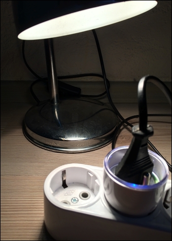
The following picture shows our new device, a Z-Wave lamp holder produced by Everspring. We have included it in the Z-Wave network, as defined in the previous chapter, and we will add the ability to switch on and switch off the device remotely from Intel Galileo.

Our next circuit is a desk lamp attached to a Z-Wave wall plug from Fibaro. We have already included the device in our Z-Wave network. We will add the ability to switch on and off the desk lamp remotely from our application.
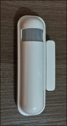
The last device in the following image includes multiple sensors produced by Philio which are a temperature sensor, illumination sensor, door/window sensor, and a motion sensor. In this chapter, we will try to only obtain illumination from a sensor. In the following chapter, we will use the motion and door/window sensor ability for security appliances.
In the previous chapter, we developed a simple application to read temperature and humidity values from an SHT11 sensor. We will use the functions from that application in our new application. You can start a new project from Eclipse or edit the previous ones.
Before proceeding, let's create new sources to increase the code reuse if needed. First, let's create our own GPIO library for basic functionality. In order to do that, we have added the galileo_gpio.h and galileo_gpio.c files to our project and copied our previously implemented functions into the galileo_gpio.c file; we also copied the function signatures to the galileo_gpio.h file and our header file looked like this:
#ifndef GALILEO_GPIO_H_
#define GALILEO_GPIO_H_
//GPIO VALUES
#define HIGH 1
#define LOW 0
#define INPUT "in"
#define OUTPUT "out"
//GPIO BUFFER
#define BUF 8
#define MAX_BUF 256
int gpio_set_value(int gpio_num, int value);
int gpio_set_mode(int gpio_num, const char* mode);
int gpio_export(int gpio_num);
int gpio_get_value(int gpio_num);
#endif /* GALILEO_GPIO_H_ */
This will enable us to use these functions for any new interaction with sensors previously mentioned and reuse the code. You can create or export any other libraries for your use to your project folder.
Then we created the thermometer.c source and the thermometer.h files to our project to define the thermometer code as a separate module. The defined function signatures in the thermometer.h file and header file will look like this:
#ifndef THERMOMETER_H_
#define THERMOMETER_H_
#include <stdint.h>
#define LSBFIRST 0
#define MSBFIRST 1
#define DATA_PIN 38  //IO 7
#define CLOCK_PIN 40 //IO 8
int shiftIn(int bit_order, int n_bits);
void shiftOut(uint8_t bitOrder, uint8_t val);
void delay(unsigned long ms);
void delayMicroseconds(unsigned int us);
float read_humidity();
float read_temperature();
void skip_crc();
#endif /* THERMOMETER_H_ */
And finally, we will create serial.c and serial.h files for serial communication with our Z-Wave USB adapter. We have made some little changes to our function signatures to make them reusable for other classes in our project. The preceding changes will give us the ability to make a more modular design and add many more features easily. The serial.h header file will be like this:
#ifndef SERIAL_H_
#define SERIAL_H_
#include <stdint.h>
int open_serial_device(const char* serial_device_path);
int close_serial_device(int device_file);
int read_from_serial_device(int device_file, uint8_t* data);
int write_to_serial_device(int device_file, uint8_t buffer[], int length);
#endif /* SERIAL_H_ */
Following the application, we will use very basic Z-Wave messages to handle messages from devices and control them. In order to interact with the device, we will implement a very basic terminal user interface, as follows, to read from stdin to execute the command. As we described in the previous section, we still keep our reader thread to handle incoming messages continuously. Our simple user interface is shown here. We will develop better interfaces in later chapters.
root@clanton:~/apps# ./smart_home
Successfully Set the Serial Device Parameters
Starting Home Manager
1 : Show Current Temperature
2 : Show Current Relative Humidity
3 : Get Current Status of Lamp Holder
4 : Switch On Lamp Holder
5 : Switch Off Lamp Holder
6 : Get Current Status of Wall Plug
7 : Switch On Wall Plug
8 : Switch Off Wall Plug
9 : Get Current Power Consumption
10: Get Energy Consumption
11: Get Power Level of Wall Plug
12: Get Power Level of Lamp Holder
13: Get Luminance of Environment
14: Quit
Enter Command to Execute:
The preceding command is our smart home application's user interface. The first two commands will call read_temperature and read_humidity functions from the first sample application developed with the SHT11 sensor, and so the SHT11 sensor should be connected to Intel Galileo. Other commands execute a simple command to manage remote Z-Wave devices.
In the previous chapter, we executed a command but didn't look into any details. The message in Z-Wave can be more complex, but we will only look into the basic ones, which will help us to switch the wall plug and lamp holder on and off.
Z-Wave commands are a list of bytes, each of which indicates a specific value for a message type. Z-Wave messages read or sent to a serial controller start with 0x01, 0x06, 0x15, and 0x18. If the first value is 0x01, it shows the start of the message. If the received message from the serial controller is 0x06, it is an acknowledgment that the message is received. If it is 0x18, it means the message can't send and so it notifies you to resend a message. Let's continue with the following simple Switch ON message in the table.
An example of Switch OFF message for Lamp Holder device to send a Z-Wave serial controller is this: 0x01, 0x0A, 0x00, 0x13, 0x04, 0x03, 0x25, 0x01, 0x00, 0x25, 0x01, 0x00.
|
Message Byte |
Byte Translation |
|---|---|
|
0x01 |
This indicates the start of the Z-Wave message. |
|
0x0A |
In this message, there are 10 more bytes after the second byte; this is the message length after the second byte. |
|
0x00 |
This byte defines the type of message, and it is a request. If the message is responded to, it would be 1. |
|
0x13 |
This defines the function of this message, which means we want to send data to the corresponding device. 0x13 is a constant value. |
|
0x04 |
This byte shows the corresponding device's ID. The lamp holder ID is 4. |
|
0x03 |
This byte shows the data length. The following three bytes define the operation or requested action from the device. This byte would be bigger if we wanted to set temperature value on a thermostat; in this case, we only send binary data to switch the lamp holder on or off. |
|
0x25 |
This defines the command type. 0x25 corresponds to the binary switch operation. Other commands are defined later in the section. |
|
0x01 |
This shows whether we will set the value of switch or get the value of switch. 1 indicates that we will set the switch. If it is 0, the device will respond with the status of the switch and the following byte will not be in this message. |
|
0x00 |
This byte indicates what value we want to set for the switch. 0 means that we will switch it off; 1 means we'll switch it on. |
|
0x25 |
This byte indicates the transmit type to the corresponding device. 0x25 indicates to send a message to the indicated node directly. |
|
0x01 |
This byte is the message identification assigned by the user or program; it is the callback ID of the message. |
|
0x00 |
This byte should be generated later; this is a checksum value. In the following section, the calculation of the checksum value will be shown. |
The first byte shows the start of the message as we've already described. The second byte is the number of bytes in the rest of the message. 0x0A means that there are 10 more bytes following this.
The third byte represents the message type, which means either respond or request. If it is a request, we place 0x00, and if it is a response, it is 0x01. The fourth byte represents a message function; 0x13 is the value for sending data to the serial controller.
The fifth byte in our example shows the node ID number in the Z-Wave controller. The Z-Wave controller automatically increases the node ID number when devices are included. In our example in this book, we first added the Philip multisensor, and so 0x02 is the multisensor device. 0x03 is the wall plug and 0x04 is the lamp holder. 0x01 is assigned to the Aeon Z-Wave controller.
After the node ID byte, 0x03 shows the length of the command to be executed by the remote device. So following 0x03 after the node ID, the three bytes are the command, which will be executed by the remote device.
After the command length information, the seventh byte shows the command class, which defines the type of action that the device needs to take and the type of value we have received. The following table shows some simple command classes and their values, which we will use in our example:
|
Command classes |
Values |
Description |
|---|---|---|
|
|
0x20 |
Set and get basic data |
|
|
0x27 |
Switch on and off |
|
|
0x25 |
Binary switch on and off |
|
|
0x32 |
Receive or request meter values |
|
|
0x71 |
Alarm data to broadcast |
|
|
0x73 |
Power level of device |
|
|
0x80 |
Battery level of device |
|
|
0x30 |
Binary sensor like motion sensor, if there is motion or not |
|
|
0x31 |
Sensor representing more than a binary value like a temperature sensor |
|
|
0x31 |
Similar to the previous command class |
|
|
0x9C |
When sensor raises an alarm |
These commands classes can only be used in the devices which support them. If you send a node a command including battery and if it doesn't have a battery, there won't be any response. Basically, commands are usually used to get the status of the device if the latter is online and in the network. Almost all device manuals include information about supported command classes for the device, and so you can check your device's manual to see what command classes you can use it with.
Note
More details and more command classes can be learned from open source projects such as OpenZWave, LinuxMCE, or the RaZberry project. The following links are great reading material to get more information about Z-Wave commands:
You can also check Z-Wave SDK from Z-Wave Alliance for more information at the following link:
The following command class value is in the message; there is a byte for the operation type if it is for setting a value in the remote device or requesting a report. 0x01 defines a setting operation and 0x02 is for getting information from a device. As we want to switch off the device, we need to send the switch off value. The switch off value is 0x00, and the switch on value is 0xFF for binary switches.
Finally, there is a transmitting type value 0x25 defined for Aeon Stick. It follows with a callback ID, which you can check from the received messages, that the message has been received by the device. Finally, the checksum value is appended in the message buffer. All messages have a checksum value at the last byte.
It will be clearer while we proceed on our example coding while trying to manage the appliances at home from Intel Galileo.
In order to send and receive Z-Wave messages to/from Z-Wave USB adapter, message classes have been defined. The message.c and message.h files are created to store functions that create messages to send and parse the incoming messages. We have also defined the necessary values to be used in the function in the message.h header file, which are shown next:
#ifndef MESSAGE_H_
#define MESSAGE_H_
#include <stddef.h>
#include <stdint.h>
#define BUFFER 256
#define REQUEST   0x00
#define RESPONSE   0x01
#define BASIC_SET  0x01
#define BASIC_REPORT  0x03
#define COMMAND_CLASS_CONTROLLER_REPLICATION    0x21
#define COMMAND_CLASS_APPLICATION_STATUS     0x22
#define COMMAND_CLASS_HAIL          0x82
#define TRANSMIT_OPTION          0x25
#define ControllerNodeID   0x01
#define MultiSensorNodeID   0x02
#define WallPlugNodeID   0x03
#define LampHolderNodeID   0x04
/*
 * Message Type
 */
typedef enum ZWAVE_MESSAGE_TYPE {
  SOF = 0x01, ACK = 0x06, NAK = 0x15, CAN = 0x18, } MESSAGE_TYPE;
/*
 * Message Function
 */
enum FUNCTION {
  SEND_DATA = 0x13, RESPONSE_RECEIVED = 0x04
};
/*
 * Multilevel Sensor Type
 */
enum SENSOR_TYPE {
  TEMPERATURE_SENSOR = 0x01, LUMINANCE_SENSOR = 0x03, POWER_SENSOR = 0x04
};
/*
 * Binary Sensor Value
 */
enum BINARY_SENSOR_VALUE {
  ON = 0xFF, OFF = 0x00,
};
/*
 * Sensor Message Types
 */
enum SENSOR_COMMANDS {
  BINARY_SET     = 0x01,
BINARY_GET     = 0x02,
BINARY_REPORT   = 0x03, // Response to the Get Command
  MULTILEVEL_GET   = 0x04,
  MULTILEVEL_REPORT   = 0x05
};
/*
 * Energy Meter Message Types
 */
enum ENERGY_METER_COMMANDS {
  METER_GET       = 0x01,
  METER_REPORT     = 0x02,
  METER_SUPPORTED_GET   = 0x03,
  METER_SUPPORTED_REPORT   = 0x04,
  METER_RESET       = 0x05
};
/*
 *WALL Plug Meter Type
 */
#define ENERGY     0x00
#define POWER     0x10
/*
 * ZWave Command Classes
 */
enum ZWAVE_COMMAND_CLASS {
  COMMAND_CLASS_NO_OPERATION     = 0x00, COMMAND_CLASS_BASIC       = 0x20,COMMAND_CLASS_SWITCH_ALL       = 0x27, COMMAND_CLASS_SWITCH_BINARY     = 0x25, COMMAND_CLASS_METER       = 0x32, COMMAND_CLASS_ALARM       = 0x71, COMMAND_CLASS_POWERLEVEL       = 0x73, COMMAND_CLASS_BATTERY       = 0x80, COMMAND_CLASS_SENSOR_BINARY     = 0x30, COMMAND_CLASS_SENSOR_MULTILEVEL   = 0x31, COMMAND_CLASS_SENSOR_MULTILEVEL_V2   = 0x31, COMMAND_CLASS_SENSOR_ALARM     = 0x9C
};
/*
 * Functions to Handle Messaging
 */
uint8_t generate_checksum(uint8_t buffer[], int length);
int parse_incoming_mesage(uint8_t* message, int length);
int handle_incoming_message(int serial_device, uint8_t message[], int length);
int binary_switch_on_off(int serial_device, uint8_t nodeID, uint8_t on_off,uint8_t callbackID);
int get_meter_level(int serial_device, uint8_t nodeID, uint8_t type,
    uint8_t callbackID);
int get_binary_switch_status(int serial_device, uint8_t nodeID, uint8_t callbackID);
int get_node_power_level(int serial_device, uint8_t nodeID, uint8_t callbackID);
int get_luminance_value(int serial_device, uint8_t nodeID, uint8_t sensor_type,uint8_t callbackID);
#endif /* MESSAGE_H_ */
We have defined all the necessary functions and constants for use in the application. In our main function, we will continue to use the reader thread as in the previous chapter, but we will make the thread also handle incoming messages to Intel Galileo.
void* reader_thread(void *arg) {
  while (1) {
    uint8_t data[256];
    int m_length = read_from_serial_device(device_file, data);
    if (m_length > 0) {
      handle_incoming_message(device_file, data, m_length);
    }
  }
}
The commands will be handled with a switch that picks the right function to call and execute a command. As shown in following code snippet, the main function reads the user input and sends it to the execute_command function to start the required function:
int main(int argc, char* argv[]) {
  //Open Serial Device
  device_file = open_serial_controller(serial_device_path);
  if (device_file < 0) {
    printf("Can't Open Serial Device %s", serial_device_path);
    return EXIT_FAILURE;
  }
  int err = pthread_create(&reader, NULL, &reader_thread, NULL);
  if (err != 0) {
    close_serial_controller(device_file);
    printf("Can't create Thread
");
    return -1;
  }
  printf("Starting Home Manager
");
  int choice = 0;
  user_menu();
  while (choice != 14) {
    printf("Enter Command to Execute:");
    scanf("%d", &choice);
    execute_command(choice);
  }
  if (pthread_join(reader, NULL)) {
    fprintf(stderr, "Error joining thread
");
    return 2;
  }
  close_serial_device(device_file);
  return EXIT_SUCCESS;
}

void execute_command(int choice) {
  switch (choice) {
  case 1:
    printf("Current Temperature is: %f Celcius
", read_temperature());
    break;
  case 2:
    printf("Current Temperature is: %f Celcius
", read_humidity());
    break;
  case 3:
    get_binary_switch_status(device_file, LampHolderNodeID, 1);
    break;
  case 4:
    binary_switch_on_off(device_file, LampHolderNodeID, ON, 2);
    break;
  case 5:
    binary_switch_on_off(device_file, LampHolderNodeID, OFF, 3);
    break;
  case 6:
    get_binary_switch_status(device_file, WallPlugNodeID, 4);
    break;
  case 7:
    binary_switch_on_off(device_file, WallPlugNodeID, ON, 5);
    break;
  case 8:
    binary_switch_on_off(device_file, WallPlugNodeID, OFF, 6);
    break;
  case 9:
    get_meter_level(device_file, WallPlugNodeID, POWER, 7);
    break;
  case 10:
    get_meter_level(device_file, WallPlugNodeID, ENERGY, 8);
    break;
  case 11:
    get_node_power_level(device_file, WallPlugNodeID, 9);
    break;
  case 12:
    get_node_power_level(device_file, LampHolderNodeID, 10);
    break;
  case 13:
    get_luminance_value(device_file, MultiSensorNodeID, LUMINANCE_SENSOR, 11);
    break;
  case 14:
    printf("Quitting.....");
    break;
  default:
    break;
}} Let's start with requesting the current status of the wall plug and the lamp holder from Intel Galileo. When we request the status, the following function will be executed:
int get_binary_switch_status(int serial_device, uint8_t nodeID, uint8_t callbackID) {
  int message_length = 11;
  uint8_t checksum = 0x00;
  uint8_t message_buffer[] = { SOF, 0x09, REQUEST, SEND_DATA, nodeID, 0x02, COMMAND_CLASS_SWITCH_BINARY, BINARY_GET, TRANSMIT_OPTION, callbackID, checksum };
  checksum = generate_checksum(message_buffer, message_length);
  message_buffer[message_length - 1] = checksum;
  return write_to_serial_device(serial_device, message_buffer, message_length);
}
We send the serial device file, node ID, and callback ID parameter to the function and create the message with COMMAND_CLASS_SWITCH_BINARY and BINARY_GET to receive the status of the device. This message length is 11 bytes as we are not setting any value and just making a status request. The following is the output received when we request the status of the lamp holder:
Enter Command to Execute: 3
Writing: 0x1 0x9 0x0 0x13 0x4 0x2 0x25 0x2 0x25 0x1 0xe0
Write Successful
Enter Command to Execute:Received: 0x6
ACK Received
Writing: 0x6
Write Successful
Received: 0x1 0x4 0x1 0x13 0x1 0xe8
Data Sent to ZWave Stack
Received: 0x1 0x5 0x0 0x13 0x1 0x0 0xe8
Data Request with Callback ID 0x1 Received
Received: 0x1 0x9 0x0 0x4 0x0 0x4 0x3 0x25 0x3 0xff 0x2c
Response From Lamp Holder Node Received: Status of Device is ON
Let's parse the received message. The first byte is 0x1, which is the start of the message. 0x9 is the length of the rest. The Node ID is the sixth byte, which is the lamp holder node ID. The next byte is 0x3, which shows the length of the command. If the 0x25 command class is received, we have 0x3, which means the report from the sensor. Finally, we have the 0xff value to indicate the status of the device, which is on here.
Let's switch off the lamp holder and then check its status. We will execute the function given below. The following message is similar to the one we examined in the previous chapter:
int binary_switch_on_off(int serial_device, uint8_t nodeID, uint8_t on_off,
    uint8_t callbackID) {
  int message_length = 12;
  uint8_t checksum = 0x00;
  uint8_t message_buffer[] = { SOF, 0x0a, REQUEST, SEND_DATA, nodeID, 0x03,
      COMMAND_CLASS_SWITCH_BINARY, BINARY_SET, on_off, TRANSMIT_OPTION, callbackID, checksum };
  checksum = generate_checksum(message_buffer, message_length);
  message_buffer[message_length - 1] = checksum;
  return write_to_serial_device(serial_device, message_buffer, message_length);
}
When we execute the command, we need to send this function the node ID, the on or off value at that time, and the callback ID. The execution is shown next:
Enter Command to Execute: 5
Writing: 0x1 0xa 0x0 0x13 0x4 0x3 0x25 0x1 0x0 0x25 0x3 0xe3
Write Successful
Enter Command to Execute: Received: 0x6
ACK Received
Writing: 0x6
Write Successful
Received: 0x1 0x4 0x1 0x13 0x1 0xe8
Data Sent to ZWave Stack
Received: 0x1 0x5 0x0 0x13 0x3 0x0 0xea
Data Request with Callback ID 0x3 Received
Enter Command to Execute:3
Writing: 0x1 0x9 0x0 0x13 0x4 0x2 0x25 0x2 0x25 0x1 0xe0
Write Successful
Enter Command to Execute: Received: 0x6
ACK Received
Writing: 0x6
Write Successful
Received: 0x1 0x4 0x1 0x13 0x1 0xe8
Data Sent to ZWave Stack
Received: 0x1 0x5 0x0 0x13 0x1 0x0 0xe8
Data Request with Callback ID 0x1 Received
Received: 0x1 0x9 0x0 0x4 0x0 0x4 0x3 0x25 0x3 0x0 0xd3
Response From Lamp Holder Node Received: Status of Device is OFF
After we execute the command, we get ACK from the controller and command callback ID, which shows that our message transmitted successfully.
As we've seen in the terminal output, we have parsed the incoming messages. It is not easy to handle messages, but we need to check each command class to decide what value has been received to the Z-Wave controller.
We can simply identify the fourth byte for what type of value is received. If it is 0x04, we know that a sensor has sent a message or response. Then we know that we need to check the sixth byte to check the node ID. It follows with the length of the command, command class, length of value, and the sensor or device value. A very basic parsing of a received message from the binary switch or a multilevel sensor is given here:
uint8_t length_of_rest = message[1];
uint8_t message_type = message[2];
uint8_t message_function = message[3];
uint8_t data_length = message[6];
uint8_t command_class = message[7];
if (message_function == RESPONSE_RECEIVED) {
  printf("Response From ");
  if (message[5] == MultiSensorNodeID) {
    printf("Multi Sensor Node Received: ");
  } else if (message[5] == WallPlugNodeID) {
    printf("Wall Plug Node Received: ");
  } else if (message[5] == LampHolderNodeID) {
    printf("Lamp Holder Node Received: ");
} }
if (command_class == COMMAND_CLASS_SWITCH_ALL) {
printf("Status of Device is ");
  if (message[9] == OFF) {
    printf("OFF
");
  } else if (message[9] == ON) {
    printf("ON
");
} else if (command_class == COMMAND_CLASS_SENSOR_MULTILEVEL_V2) {
  if (message[8] == MULTILEVEL_REPORT) {
    if (message[9] == TEMPERATURE_SENSOR) {
      printf("Temperature Value is %d Fahreneit
", message[12]);
    } else if (message[9] == LUMINANCE_SENSOR) {
      printf("Illumination is %d %
", message[11]);}}}
The Philio multisensor reports when there is a change in any of the sensors. Let's hold our desk lamp directly to the Philio multisensor to measure luminance and then let's switch off the wall plug with command 8. Now, read the luminance value change:
Received: 0x1 0xb 0x0 0x4 0x0 0x2 0x5 0x31 0x5 0x3 0x1 0x5a 0x9b
Response From Multi Sensor Node Received: Illumination is 90%
Enter Command to Execute: 8
Received: 0x6
ACK Received
Writing: 0x6
Write Successful
Received: 0x1 0x4 0x1 0x13 0x1 0xe8
Data Sent to ZWave Stack
Received: 0x1 0x5 0x0 0x13 0x6 0x0 0xef
Data Request with Callback ID 0x6 Received
Received: 0x1 0xb 0x0 0x4 0x0 0x2 0x5 0x31 0x5 0x3 0x1 0x5 0xc4
Response From Multi Sensor Node Received: Illumination is 5%
These kinds of sensor data are very useful to automate your home. You can add the logic to your application to switch off the light if the illumination received is more than 20 percent or switch it on if it is less than 5 percent according to this sensor.