
Remote switches are another key component required to automate your home. A remote switch gives the ability to remotely switch on and switch off if the plugged device is required to be open or closed. Some remote switches also have energy meters on them that provide the amount of consumed energy to the user.
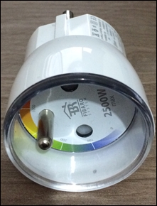
We have a remote wall plug from Fibaro that uses the Z-Wave protocol to communicate. The Fibaro wall plug has a relay switch to turn it on/off and an energy meter to provide a power consumption value. You can see the device in the following image:
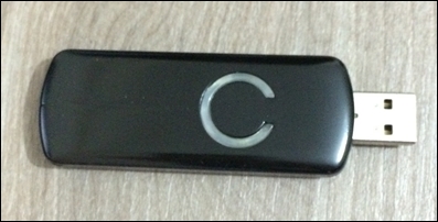
We will try to switch it on and off by sending basic commands through a Z-Wave controller. We will use the Aeon Labs Z-Stick S2 USB adapter for our controller. As Intel Galileo has a USB host port, we will connect the Z-Wave controller from Intel Galileo's USB host. The Z-Wave USB adapter uses serial communication when it's on a host device, and so we will implement a couple of C functions to create communication with the device. You can see the USB adapter in the following image:
While we are trying to work with Z-Wave USB adapter, we will learn some new features to work with Intel Galileo.
Note
Z-Wave adapters need to include the device before you program it. The inclusion steps for devices are covered in the device manuals. Either you can read them from the paper provided in the product box or you can access them from their official web sites.
The Aeon Labs Z-Stick S2 manual is available from here: http://aeotec.com/z-wave-usb-stick/913-z-stick-manual-instructions.html
The Fibaro wall plug manual is available from here: http://www.fibaro.com/manuals/en/FGWPE_F-101-Wall-Plug/FGWPE_F-101-Wall-Plug-en.pdf
The Aeon Labs Z-Stick requires the cp210x kernel module to be loaded to create serial communication device: /dev/ttyUSB0.
We require the cp210x kernel module for our Intel Galileo image. In order to do that, we will go to our build system with Yocto Project and build the cp210x kernel module; we'll then install it into Intel Galileo using the following steps:
- Go to the directory that you created for building the SD card image for Intel Galileo. This is shown here:
$ cd /home/onur/galileo_build/meta-clanton_v1.0.1 - We need to set up the environment variables again. If your terminal session is still open from the first chapter, you don't need to rerun this command. This is shown here:
$ source poky/oe-init-build-env yocto_build - Let's reconfigure kernel and pick the cp210x module to build. This is shown here:
$ bitbake linux-yocto-clanton –c menuconfigThe last command will open the kernel configuration menu window for you. In order to select cp210x module, select Device Drivers, USB Support, USB Serial Converter Support and finally USB CP210x Family of UART from the menu; save the configuration and exit.
- Build the kernel module with the following command:
$ bitbake linux-yocto-clantonThe final command will build the module and create the installable package in
yocto_build/tmp/deploy/ipk/clantondirectory namedkernel-module-cp210x_3.8-r0_clanton.ipk. - Copy the file to Intel Galileo; install and load the kernel module as shown here:
$ scp kernel-module-cp210x_3.8-r0_clanton.ipk [email protected]:/home/root
$ opkg install kernel-module-cp210x_3.8-r0_clanton.ipk
- The final command will install the module to the
/lib/modules/kernel/drivers/usb/serialdirectory. Load module to Intel Galileo with this command:$ modprobe /lib/modules/kernel/drivers/usb/serial/cp210x
Serial communication is a widely used protocol to receive and transfer bytes from/to devices. For example, the 6-pin FTDI cable you've connected to your Intel Galileo and your PC's USB host communicate using the RS232 serial protocol, to send the keyboard data you entered on minicom and get the terminal output to your device.
Most of the PC interfaces of home automation controllers use serial communication. We will use the Aeon Labs Z-Stick, but there are other USB adapters that can be found for use with Z-Wave devices.
Note
The Insteon and EnOcean USB adapters are also available, and can use serial communication as well. Refer to the Insteon USB Interface here: http://www.insteon.com/2413U-PowerLinc-USB.html.
First we need to set up the serial communication interface from our application. We will continue with a new project only with this purpose in mind. First, we will open the device file /dev/ttyUSB0 and then we will set the serial interface with a 1,15,200 baud rate, 8 data bits, 1 stop bit, and no parity bits. If this setting isn't done right, the sent or received data will be corrupted.
We defined the function open_serial_device to get the device file and set the device communication options as shown here:
int open_serial_device(const char* serial_device_path) {
 //Open Device File /dev/ttyUSB0
 int device_file = open(serial_device_path, O_RDWR | O_NOCTTY, 0);
 if (device_file < 0) {
    printf("Can't Open Serial Controller
");
    return -1;
  }
struct termios options;
 int bits;
  bits = 0;
  ioctl(device_file, TIOCMSET, &bits);
  /**
   * Get Current Options
   */
  tcgetattr(device_file, &options);
  //No Parity
  options.c_iflag = IGNPAR;
  options.c_iflag |= IGNBRK;
  //Set 8 Data bits
  options.c_cflag |= CS8 | CREAD | CLOCAL;
  options.c_oflag = 0;
  options.c_lflag = 0;
  int i;
  for (i = 0; i < NCCS; i++) {
    options.c_cc[i] = 0;
  }
  options.c_cc[VMIN] = 0;
  options.c_cc[VTIME] = 1;
  //Set Baudrate for Serial Communication
  cfsetspeed(&options, B115200);
  if (tcsetattr(device_file, TCSANOW, &options) < 0) {
    printf("Can't Set The Serial Device Parameters
");
  } else {
    printf("Successfully Set the Serial Device Parameters
");
  }
  //Flush the waiting bits/bytes
  tcflush(device_file, TCIOFLUSH);
  return device_file;
}
In the function, we first open the serial device file, then we request the current options from system function tcgetattr and complete the settings to make the device ready for communication.
Now, we will proceed to implement the methods to read and write bytes from/to the serial device using the read_from_serial_device and write_to_serial_device functions.
The following function writes bytes to the serial device and then checks whether the bytes are written correctly:
int write_to_serial_device(int device_file, uint8_t buffer[], int length) {
  int i = 0;
  int count = 0;
  printf("Writing: ");
  while (count < length) {
    if (write(device_file, &buffer[count], 1) == 1) {
      printf("0x%x ", buffer[count]);
      count++;
    } else {
      printf("
 Can't Write Byte
");
      break;
    }
  }
  if (count == length) {
    printf("
Write Successful
");
    return count;
  } else {
    printf("
Can't Write All Frame to Serial Device
");
    return -1;
  }
}
The following function read bytes from the serial device:
int read_from_serial_device(int device_file, uint8_t *data) {
 int bytesRead;
 uint8_t buffer[256];
 //Read Data From Serial Device to Buffer
 bytesRead = read(device_file, buffer, sizeof(buffer));
 //Print Bytes
 data = malloc(sizeof(uint8_t) * bytesRead);
 if (bytesRead > 0) {
  int i = 0;
  printf("Received: ");
  for (; i < bytesRead; i++) {
   data[i] = buffer[i];
   printf("0x%x, ", data[i]);
  }
  printf("
");
 }
 return bytesRead;
}So we have implemented the required functions for serial communication. In order to communicate correctly with the Z-Wave controller, we need to learn basic Z-Wave commands to get and set values from/to the remote wall plug. We will obtain help from open source projects to get information about Z-Wave communication.
In the following sample, we will only use basic commands to switch on/off and read energy meter value from the Fibaro wall plug. We will not parse the raw data received from the Z-Wave controller. In the following chapter, we will parse the received values and create a more automated application by bringing together the blocks.
Basically, the Z-Wave controller creates a home network and generates a number (or a home ID) for that. In this way, it isolates your devices from any other controller to reach out and give a number for each of the devices or nodes added, starting from 2. The first node is the controller itself.
The following function is the main function that is used to simply get power information from the wall plug. We create a thread to read the received data while we send data to the controller.
void* reader_thread(void *arg) {
  while (1) {
    read_from_serial_device();
}
 return NULL;
}
int main(int argc, char* argv[]){
//Open Aeon Stick Z-Wave
 device_file = open_serial_device(SERIAL_DEVICE);
 if (device_file < 0) {
  return EXIT_FAILURE;
 }
  //Create Thread
  pthread_t reader;
  int err = pthread_create(&reader, NULL, &reader_thread, NULL);
  if (err != 0) {
    close_serial_device();
    printf("Can't create Thread
");
    return -1;
  }
uint8_t get_energy_meter[] = { 0x01, 0x0a, 0x00, 0x13, 0x03, 0x03, 0x32, 0x01, 0x00, 0x25, 0x16, 0xe6 };
  //Send Energy Meter Value
  write_to_serial_device(get_energy_meter, 12);
if (pthread_join(reader, NULL)) {
    fprintf(stderr, "Error joining thread
");
    return 2;
  }
  close_serial_device(device_file);
  return EXIT_SUCCESS;
}
In this sample, we have a Z-Wave command to send to the corresponding node and Fibaro wall plug to receive energy readings as raw values. In this command, the first four bytes form the home ID, the fifth byte forms the node ID or device ID assigned by the controller, then we have the command code and address, and finally the checksum of the bytes.
When we build and run the application, we will have the following outputs. The first received byte is an acknowledgment and then the next 18 bytes are for data.
root@clanton:~# ./zwave-galileo
Writing: 0x1 0xa 0x0 0x13 0x3 0x3 0x32 0x1 0x0 0x25 0x16 0xe6
Write Successful
Received 1 Bytes: 0x6
Received 18 Bytes: 0x1 0x10 0x0 0x4 0x0 0x3 0xa 0x32 0x2 0x21 0x44 0x0 0x0 0x0 0x33 0x0 0x0 0x84
Communication with remote Z-Wave devices is being handled with similar messages sent to the controller. For example, in order to query the controller for the home ID and device ID, you can send "0x1 0x3 0x0 0x20 0xdc" bytes to get 10 bytes of data, four bytes (the fifth to eighth bytes), the home ID, and the ninth byte to represent the node ID of the controller. Some common messages used to get data from the serial controller are listed in the following table:
|
Message sent |
Message task |
|---|---|
|
0x1 0x3 0x0 0x20 0xdc |
Requests the home ID and node ID from Z-Wave controller. |
|
0x01, 0x03, 0x00, 0x15, 0xe9 |
Requests the Z-Wave version of the serial controller. |
|
0x01, 0x03, 0x00, 0x07, 0xfb |
Requests the capabilities of the serial controller. The serial API version, manufacturer ID, product type, and product ID can be learned from this message. |
|
0x01, 0x03, 0x00, 0x02, 0xfe |
Requests initial data from the serial controller. Responses includes information about devices included in the device. |
You can follow up with Z-Wave messages (frames) with open source projects for more information on this.
Note
The following wiki page shows the Z-wave command classes: http://wiki.micasaverde.com/index.php/ZWave_Command_Classes