
The term structural logic is used to describe how structural elements are combined to form different building types. Structures are classified here as mainly compressive or mainly tensile, and are geometrically described as either a two-dimensional shape that is used repeatedly (iterated) or as a three-dimensional (double-curved) surface.
It is considered that, to some degree, any of the construction elements described in the previous section can be applied to any type of structural form. Because of this, the illustrations in this section attempt to cover not only different types of structural logic but also a variety of construction solutions and the particular structural elements that they employ.
Two-Dimensional Shapes
In two dimensions, compressive structures can enclose an area in four basic ways: as a beam and post, an A-frame, an arch or a portal frame. These two-dimensional elements or shapes may then be iterated – used repeatedly – to create volumes through extrusion and/or rotation. A series of building types derive their forms from the iteration of two-dimensional shapes, and these are outlined in this section. Derivations of the arch have been a particular source of creative structural logic, and these are covered separately.
Surfaces
Certain structural forms cannot be described by applying a simple geometric procedure to a curve or arch. Geometrically, spheres, cylinders and cones may be described as surfaces that enclose (or partially enclose) space. In a similar way, cubes, parallelpipeds and other polyhedra may be described as surfaces. A surface may be described as a two-dimensional geometric figure (a collection of points) in three-dimensional space. Mathematically, surfaces are normally defined by one or more equations, each of which gives information about a relationship that exists between coordinates of points on the surface, using some suitable (e.g. Cartesian) coordinate system. A series of building types derive their forms from surface geometry, and these are outlined in this section.
Tensile Structures
Geometrically, a tensile structure is normally described as a surface. Such structures are constructed by stretching fabric (membranes) or a network of cables (cable nets) using masts or other shapes to carry the compressive loads and ground anchors to resist the upward pull. For these surfaces to be structurally efficient – where the whole surface is in equal tension and there is no structurally redundant material – there tend to be certain geometric shapes. Mast-supported membrane and cable net structures develop saddle type or anticlastic shapes – they consist of two curvatures (hyperbolic paraboloids) that traverse in opposite directions. Air-supported membrane structures tend to develop synclastic shapes – they curve towards the same side in any direction, as with a sphere.
Compressive Structures / Two-Dimensional Shapes: Post and Beam, A-Frame, Portal Frame, Arch
Post and Beam
The simplest structure is where two vertical columns support a beam, which spans between them.
A-Frame
This structure spans through triangulation, with each side leaning against the other. If its legs are not fixed at their lower end, the structure needs horizontal bracing that is mainly in tension to prevent the legs from splaying out under load.
Portal Frame
A portal frame is a combination of a post and beam and an A-frame. It works in a similar way to a Vierendeel truss, being composed of a rigid frame that is made up of elements with a deep cross-section to help brace the structure.
Arch
An arch may be curved or pointed. The curved arch is a continuous compressive element that distributes loads through its curvilinear form. The loading in an arch increases towards its base, which must be anchored or tied to prevent the arch from splaying outwards.
Catenary, Parabolic and Elliptical Curves
Each of these curves is considered to be structurally efficient when employed as an arch, the elliptical arch spanning longer distances than standard arches due to its flatter curve. A catenary curve may be derived from inverting the profile of a hanging chain. Parabolic curves also occur naturally, as in the profile of a water jet, and both parabolic and catenary curves can be expressed as a quadratic equation derived from plotting them on a graph. In a suspension bridge, the cables that are stretched between the masts form a catenary curve, however once the cables become loaded (by hanging a deck from vertical cables placed at regular intervals) the curve becomes parabolic. When a catenary curve is inverted, it forms a naturally stable arch. Arches formed in this way are structurally efficient since the thrust into the ground will always follow the line of the arch.
The parabola, in its simplest form, is:
y = x^2
The catenary is defined by the hyperbolic cosine:
y = cosh(x) = (e^x + e^-x)/2
Pin-jointed Arches
The pin joint is a structural connection that allows for adjustment through rotational movement at the point of connection, similar to a hinge. Arches employ pinned joints at the base and/or apex, partly for ease of construction and partly to allow for differential movement. If the arch were to be fixed rigidly, stresses would build up whenever it became subject to non-uniform external loading, such as ground movement.

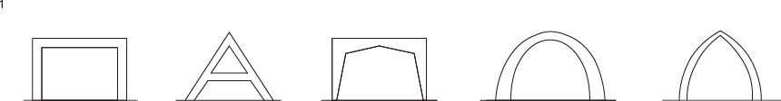
1 Primary (2D) compressive shapes. From left to right: post and beam, A-frame, portal frame, curved arch, pointed arch.
2 Catenary curves.
3 A single-pinned arch will allow for limited movement at ground level. A 2-pinned arch allows for one side or the other to act as a pivot point. Adding three hinges allows two halves to lean against each other, offering multiple degrees of freedom of movement.
4, 5, 6 Post and beam.
7 Portal framing system by Lamisell Ltd, UK.
8 A-frame.
9, 10 Although these structures designed by Nox Architecture are arching, the spanning principle is that of a portal frame.
11 A parabolic curve may be drawn by cutting any oblique section through a cone. The intersection of a cone with a plane results in an ellipse.
Compressive Structures / Two-Dimensional Shapes: Vault, Dome
See also: Pantheon p142
Crystal Palace p148

Barrel Vault
A barrel (or wagon) vault is formed by extruding an arched shape. It maintains a constant cross-section throughout its length.
Groin Vault
A groin vault is the result of two barrel vaults intersecting at right angles. The line of intersection of vaulting surfaces is an arched diagonal known as the groin.
Gothic Vault
While a traditional Romanesque arch was a curve, Gothic arches borrowed from the Muslim tradition and were pointed. Gothic roofs also combined diagonal ribs with the groin vault (although it is still not known whether they helped support the vault). Variations include the diamond vault, the stellar vault and the fan vault.
Ribbed Dome
A ribbed dome is formed by rotating a set of identical arches about a central axis.

1 From left to right: two examples of barrel vaults, two examples of pointed vaults, three diagrams of ribbed domes.
2 Barrel vault made from curved, iron trusses. The Natural History Museum, London, UK, designed by Alfred Waterhouse and completed in the late nineteenth century.
3 Brick groin vault at the Natural History Museum.
4 Ribbed dome. The horizontal members act as a continuous ring that holds the ribs in tension and prevents them spreading outwards under the load. The dome is made from curved, laminated timber beams, fabricated by bending a strip of timber and then gluing successive layers or strips on top of each other; each layer maintains the curved shape of the one below.
5 Downland Gridshell: patented joint used in construction.
6 Downland Gridshell, Weald and Downland Museum, Sussex, UK, Edward Cullinan & Partners with Buro Happold and the Green Oak Carpentry Company. These lightweight, timber lattices need to be tensioned around their edge using a continuous (“ring”) beam.
7 Fan vault at Wells Cathedral, Somerset, UK, built largely in the late twelfth and early thirteenth centuries.
8 Le Galerie des Machines was built for the 1889 Paris exhibition. Designed and engineered by Duter, Contamin, Pierron and Charlton, the hall was formed by a series of three-pinned, trussed, steel portal frames.
9 Berlin Hauptbahnhof, Berlin, Germany, by Gerkan Marg and Partners.
10 Orangery, Prague Castle, Czech Republic, designed by Eva Jiricna and engineered by Mathew Wells of Techniker.
Compressive Structures / Three-Dimensional Surfaces: Diamatic Dome, Lamella Dome
See also: Palazetto Dello Sport p156
The Houston Astrodome p158
The USA Pavilion p162

Diamatic Dome
Spans may be increased by using this system which combines the arch with the ”A” frame. The primary structure is made from any number of intersecting arches with lateral rings, as with a conventional ribbed dome. The arches are then reinforced with triangular bracing.
Lamella Dome
This dome employs a helical arrangement of ribs, which when used in opposing directions act to brace as well as support the structure. The dome is generated with concentric rings, where each subsequent ring is rotated by a half module. This reduces the length of the ring tubes as the geometry proceeds towards the apex. The separation between rings in Lamella domes can be varied so they are equilateral triangles forming each ring.
The St. Louis Arena was one of the first large scale lamella domes constructed in the US, which opened in 1929 (demolished 1999) and was designed by Dr Gustel R. Kiewitt. Kiewitt created this huge roof, 145m long and 84m wide, using small Douglas fir timbers to create a triangulated “fish-scale” structural shell. Kiewitt was also involved in the design of the Houston Astrodome (1962–64), with a span of 196m. The same structural principles were subsequently applied in the construction of the recently refurbished New Orleans Superdome (1973), 207m in diameter.
The lamella principle of a crisscrossing pattern of short structural members (lamellae) interlocking in a diamond pattern can also be used to form a vaulted roof structure. Hugo Junkers (1859-1935), more famous for his aeronautical innovations, patented a steel lamella roof construction system in the early 1920’s, based upon the earlier timber lamella roofs of Fritz Zollinger. Two examples of Junkers lamella system utilizing lightweight pressed metal components were built as aircraft hangars at Rodmarton, Gloucestershire (1938-1939). These innovative parabolic arch structures have subsequently been listed, siting similarities with Luigi Nervi’s lamella-type structures built for the Italian air force.

1 From left to right: diamatic dome, lamella dome.
2 The Platonic solids. In geometry, a Platonic solid is a convex, regular polyhedron of which there are no more than five. The name of each solid derives from the number of faces, i.e.
a Tetrahedron (four triangles)
b Cube (six squares)
c Octahedron (eight triangles)
d Dodecahedron (12 pentagons)
e Icosahedron (20 triangles) The solids are unique in that the sides, edges and angles are all congruent.
3 The Houston Astrodome, Texas, USA (see also p.158). A diamatic dome.
4 The Palazzetto Dello Sport, Rome, Italy, Pier Luigi Nervi (see also p.156). A lamella dome.
5 30 St Mary Axe, London, UK, Foster & Partners (see also p.176). A structure whose surface geometry is derived from a lattice of double helixes, similar to a lamella dome, also known as a tubular or exo-skeletal structure.
6 The roof over the Great Court, British Museum, London, UK, Foster & Partners. On plan the roof consists of a series of radiating lines that are either perpendicular or tangential (like bicycle spokes) to the reading room dome in the center. Since the dome was not in the center of the quadrangle, computer software was designed in order to calculate the optimum adjustments for each facet: there are over 1826 unique (six-way), fully welded connection nodes.
7 Roman Lamella dome – cross-section.
8 Development of a diamatic dome.
9 Structural elements of a lamella dome.
Compressive Structures / Three-dimensional Surfaces: Geodesic Dome
See also: Palazetto Dello Sport p156
The Houston Astrodome p158
The USA Pavilion p162
Geodesic Dome
The geodesic dome patented by Richard Buckminster Fuller in 1954 is known to be the most structurally efficient of the domes derived from the icosahedron (a twenty sided polyhedron – one of the Platonic or Regular Solids). In the patent application, Fuller described the structure as a spherical mast, which evenly distributes tension and compression throughout the structure. The geodesic dome combines the structural advantages of the sphere (which encloses the most space within the least surface, and is strongest against internal pressure) with those of the tetrahedron (which encloses the least space with the most surface and has the greatest stiffness against external pressure).
A geodesic structure distributes loads evenly across its surface and, as with a space frame, is efficient to construct as it is composed entirely of small elements. The geodesic dome is the product of a geometry based on the shortest line between two points on a mathematically defined surface; it takes its name from the science of geodesy – measuring the size and shape of the earth. A geodesic dome consists of a grid of polygons that is the result of the geodesic lines (or great circles) intersecting. A great circle is (to quote Fuller) “…a line formed on a sphere’s surface by a plane going through the sphere’s center.” And a three-way “great circle” grid can symmetrically subdivide the faces of the icosahedron mapped onto a sphere.
The number of times that you subdivide one of the triangular icosahedra faces is described as the frequency; the higher the frequency, the more triangles there are, the stronger the dome will be. The scalability of the geodesic dome is interesting, with Fuller writing in his seminal publication Critical Path “…every time a geodesic dome’s diameter is doubled, it has eight times as many contained molecules of atmosphere but only four times as much enclosing shell…” This realization led to Fuller’s proposal in 1950 to enclose the whole of midtown Manhattan in a 2 mile diameter geodesic dome whose physical enclosure would have weighed significantly less than the volume of air contained within and whose structure would be largely rendered invisible because of physical proximity and our relative visual acuity.
Fuller and his consultancy companies, Synergetics and Geodesics Inc., produced many structural types of geodesic enclosure working in collaboration with other architects and engineers. Fuller also licensed his technology, which included patented geometric configuration and various connection details. Domes were fabricated from a wide range of materials, which included cardboard, plywood sheets, sheet steel, and Fiber Reinforced Plastics.

1 The Eden Centre, Cornwall, UK. Grimshaw & Partners. A set of interlinking domes (modelled on the highly efficient structural geometry of soap bubbles) made up of hexagonal components.
2 USA Pavilion, 1967 Montreal Expo, Canada, Buckminster Fuller (see also page 162).
3 Citizens State Bank, Oklahoma City, Buckminster Fuller with Kaiser Aluminum. Folded shell dome based on the icosahedron.
Compressive Structures / Shell and Monocoque
See also: Kresge Auditorium p154
Lords Media Centre p174
Compressive structures may also be designed by utilizing the properties of particular materials. Shell and monocoque structures are two examples.
Cast Reinforced-Concrete Shell Structures
These are traditionally made by pouring concrete into a mold that contains a network of reinforcing bars. You could think of a shell structure as a warped, reinforced-concrete slab. It is usually cast over a timber mold known as the formwork. A type of concrete known as ferrocement can be sprayed onto a surface – a technique that enables the use of inflatable formwork.
Monocoque Structures
These derive their strength from sandwiching a framework between thin panels. Known also as stressed skin structures, and commonly used in the aircraft, automobile and shipbuilding industries, they rely upon the outer panels to stiffen the structures – the outer skins carry all or most of the torsional and bending stresses.
Form Finding
During the last century, both architects and engineers developed ways to design complex, double curving, compressive surfaces by experimenting with physical models – specifically, by employing a three-dimensional version of the catenary curve. A net or fabric is suspended from a set of points and then fixed in position using plaster and/or glue. This is then flipped over (mirrored horizontally) to create a thin, shelllike form. Due to their structural efficiency – the model in pure tension becomes one in pure compression – these forms are known as minimal surfaces.

1 Anticlastic and Synclastic geometry: any surface that is curved in opposite ways in two directions – positively along one principle axis and negatively along the other (i.e. saddle-shaped) – is known as anticlastic; surfaces that curve toward the same side in all directions are known as synclastic. Hence, the catenary curve can be rotated to form a (synclastic) catenoid and the parabolic curve to form a (synclastic) hyperbolic parabola. Structurally, both of these forms may be applied either as thin, compressive shell structures or as tensile, cable nets.
2 L’Oceanogràfic, Valencia, Spain, Felix Candela. Reinforced concrete shell; a series of hyperbolic paraboloids meet centrally as in a groin vault.
3 Ruled Surface – a synclastic surface can also be formed using straight or ruled lines. This is not only convenient for the draftsman but also aids in generating a structural grid.
4 The Sydney Opera House, Sydney, Australia, designed by Jørn Utzon and engineered by Ove Arup (see also page 166). The Opera House was designed as a series of reinforced-concrete shells.
Tensile Surfaces / Membrane, Cable Net and Tensegrity
See also: The German Pavilion p160

Fabric
While some fabrics stretch to varying degrees, the design of pressurized or tensile membrane structures involves patterncutting techniques similar to tailoring: fabric seams are stitched and welded together, and may often be reinforced with cables (as in a cable net structure).
Air-Supported Membranes
In the case of airtight fabrics, membrane structures can be formed using air pressure alone. Superpressure (also known as inflatable or pneumatic) buildings maintain their shape by pumping air into the structure. As with a tire, air acts in compression to carry the loads, while the fabric maintains the overall shape under tension.
Cable Net
While a membrane structure relies partially upon its own elasticity to find its natural form, a cable net structure finds its optimum form under tension by having adjustable nodes that allow the cables to slide over each other wherever they interconnect.
Tensegrity
The word comes from tensile integrity, and Buckminster Fuller described the principle as “structure using distributed tension to hold islands of compression.” Tensegrity produces minimal, lightweight structures wherein cables are tensioned against compression elements that are independent of (do not touch) one another.

1 Three-dimensional tensile surfaces. From left to right: mast-supported membrane, air-supported membrane, cable net, tensegrity.
2 North African Bedouin tents made from wooden posts and goatskin membrane.
3 German Pavilion, 1967 Montreal Expo, Canada, Frei Otto (see also page 160).
4 Mast-supported membrane structure. Anticlastic (saddle-shaped) geometry is inherent to efficient membrane structures.
5 Detail of membrane connection to mast.
6, 7 Millennium Dome, London, UK, Richard Rogers. A part cable net and part membrane structure, where the cables act as reinforcements for the tensile fabric.
8 Arch-supported membranes.
9, 10 Tennis court enclosure, London, UK, Birds, Portchmouth, Russum. Superpressure buildings maintain their shape by pumping air into the structure.
11 Tensegrity model.
12 Aviary, London Zoo, UK, designer Lord Snowdon, architect Cedric Price and engineer Frank Newby. A tensegrity structure.
13 Tensegrity sculpture by Kenneth Snelson. He describes the principle as “floating compression.”