
With all structural forms, the size, number and location of the different structural elements will be choices made by the designer as part of the overall design concept. The designer must be able to describe how the different elements work individually, and how they contribute to the way the building works as a uniform structure. Structural elements are classified as either bearing – those that carry loads to the ground mainly in compression (such as columns and foundations) – or spanning, i.e. those elements that must span or bridge space (such as floors and roofs).
Bearing Elements
A structure made with solid walls has the advantage that the walls also brace the structure – you could think of them as extended columns in a pinwheel. These walls can support floors and roofs, and are known as loadbearing walls. All other (non-loadbearing) walls are either partitions when used internally or weathering/ insulating screens when used externally (see Climatic Envelope, pages 80–101). Loadbearing walls create a climatic enclosure but at the same time have the disadvantage that they carry their loads to the ground throughout their length and hence require a supporting beam or continuous strip foundation (see Foundations, page 42).
Floors and roofs may also be carried on a series of columns each of which will have its own, independent foundation. A loadbearing wall may also be reinforced by embedding columns into the wall at various intervals. These are known as engaged columns.
Foundations
Foundations are required for structures that carry loads to the ground, and are usually created by filling holes dug into the ground with heavy material such as concrete or stone. Alternatively with soft ground, rods – known as piles or piers – can be inserted to the point where stability is achieved either by piercing through to the bedrock, or through friction with the soil itself.
Spanning Elements
Roofs and floors can be constructed in two basic ways, either using multiple, linear spanning elements – beams – or two-way spanning elements – slabs. Roofs and floors may be considered as similar structural elements since they both carry live loads directly. Floors must carry the load of people, furnishings, and equipment while roofs must account for people, equipment, snow, and wind.
Bearing Elements / Bearing Walls: Stacked Masonry
Bell Rock Lighthouse p146

Masonry
Loadbearing walls are traditionally made from piling up bricks or blocks made from dense, massive materials such as clay, stone, or concrete. Such walls are referred to as masonry walls. Each layer of blocks is known as a course, and these are laid in patterns so that joints in between them do not run vertically through the wall. These patterns are known as the bond. Stone walls, particularly where they are used as boundary walls, may be constructed without mortar, relying entirely upon gravity for their stability; these are known as drystone walls. Most modern loadbearing masonry, however, is bonded together using a ⅜ in bed of mortar, which is a mix of soft sand and cement (usually at a ratio of 4 : 1) and water. Adding lime to the mortar allows the mix to remain plastic so that it can adjust to any movement in the wall and prevent cracking.
Clay Bricks
These are made from extruding or pressing clay into a mold and baking the bricks in a kiln. Bricks are often made with a recess (known as a frog) or with 1 in holes running through them so that the mortar binds the bricks in such a way as to restrict any linear movement. A standard brick is 8 x 3 ½ x 2 ½ in. The small face of a brick is known as its header, and the long face as its stretcher.
Adobe Bricks
Adobe bricks are made from mud (for compression) and straw (for binding – tension) and are baked in the sun. The walls are then usually rendered by plastering mud onto the surface to improve cohesion and weathering.
Concrete Masonry Units
Concrete Masonry Units (CMU) are generally made as hollow blocks that are laid up in courses bonded by mortar much like clay brick. For additional strength and resistance to lateral loads, steel reinforcing bars may be run vertically through the cells of the block, and the cells grouted solid. The standard size for CMU is 8 x 8 x 16 in.
Thickness of Masonry Walls
Traditional stone walls were often very thick – not only to carry floors and roofs, but also to protect the occupants of the building from outside threat.
For modern, two- or three-story structures, however, an 8 in thick wall is usually structurally sufficient. The better masonry bearing walls built today employ an interior wythe of CMU that carries the structural loads, a cavity (for insulation, waterproofing, and drainage), and an outer masonry veneer as exterior finish.

1 Flemish-bonded brickwork.
2 Cavity wall.
3 Reinforced blockwork.
4 A, Alternate courses of Flemish-bonded brickwork. B, Alternate courses of English-bonded brickwork. C, Plan of cavity wall: two skins of brick or blockwork are tied together with a gap of around 4 in – for insulation and to prevent moisture penetrating – in the middle. Metal ties are embedded into the mortar beds at roughly 1 ft 6 in intervals, horizontally and vertically.
5 Flemish-bonded loadbearing brickwork.
6 Traditional loadbearing stonework.
7 Machu Picchu, Andes, Peru. Loadbearing stonework cut with great accuracy by hand and laid dry, i.e. using no mortar.
8 Loadbearing cavity wall. The outer skin is brickwork, the inner skin artificial blocks. One block is the size of six bricks.
Bearing Elements / Bearing Walls: Composite Construction
Cast Concrete
As well as being made by stacking up modular blocks, bearing walls may also be constructed through casting or molding “state-change” materials – those that can be poured into a mold and that will then solidify and take the shape of that mold through one of a number of chemical processes. The most common method of casting a loadbearing wall is by using reinforced concrete. Wet concrete is poured into a mold that contains steel reinforcing bars. These types of bearing wall may be constructed off-site in large, modular panels – a process known as precasting.
Additional Composites
Loadbearing walls can also be constructed using materials within a composite framework. Sandwiching panels around an inner core or framework results in a form of construction known as monocoque or stressed skin. The two outside panels act in tension to stiffen the inner core.


1 Composite bearing walls: reinforced concrete and two stressed-skin varieties – framed and laminated.
2 In this instance, concrete is pumped into a formwork consisting of prefabricated hollow, polystyrene blocks which are left permanently in place to insulate the building. The outside surface is then weatherproofed.
3 Concrete has been poured into timber shuttering. The shuttering can be removed – struck – once the concrete has set hard, usually after 24 to 48 hours. This is known as the curing process, and concrete will reach 75 per cent of its full strength in around seven days, and will only reach maximum strength after a period of weeks.
4 Reinforced-concrete wall, cast on site – in situ. As well as bearing the floor loads, the wall is acting to resist lateral loads – to brace the structure. While concrete is very strong in compression, it needs reinforcing with steel bars to resist tensile forces.
5 Loadbearing concrete wall, showing reinforcing bars.
6 Cast-concrete loadbearing wall. The holes are where the two sides of the shuttering were tied together to prevent them being forced outward by the weight of the wet concrete. The surface of the concrete takes the imprint of the shuttering material – in this case timber planks.
7 Reinforced-concrete walls, cast in situ to support a stairwell.
8 Prefabricated structural insulated panel (SIP) made by bonding oriented strand board (OSB) – to a foam core, a process known as lamination.
See also: The Crystal Palace p148
HSBC Headquarters p168

Walls and roofs can be supported on columns (also known as pillars or piers) as well as by loadbearing walls. The intervals between columns in a grid is directly related to their cross-sectional size – the smaller the section, the closer together they will be. Assuming a 26 ft 3 in by 26 ft 3 in grid, columns can be roughly sized (cross-sectional area) on the basis of the number of floors supported:
1 story 1 ft x 1 ft
6 storys 2 ft 3 in x 2 ft 3 in
11 storys 3 ft 3 in x 3 ft 3 in
16 storys 3 ft 11 in x 3 ft 11 in
Buckling
The length of a column will determine the way in which it will react under load. The taller the column, the more likely it is to buckle (bend or “kneel”), and its stiffness rather than its compressive strength becomes important. It is for this reason that a tubular section column is more efficient than a solid section one.
Loads
The loads in a column gradually increase toward the base. To compensate for this, columns may taper or get narrower towards the top.
Classical Orders
Ancient building types are classified by the type of column used in their construction. Known as the Classical Orders, columns are divided into Doric, Ionian, and Corinthian – all of Greek origin – Tuscan and Composite, which are of Roman origin. A classical column is described using three main elements: its shaft, its base and its capital, and the different orders may be distinguished by the detailing and proportioning of these. The height of a column is measured as a ratio between the diameter of the shaft at its base compared to its height.
For example, a Doric column can be described as being seven diameters high, an Ionic column as eight diameters high and a Corinthian column as nine diameters high.
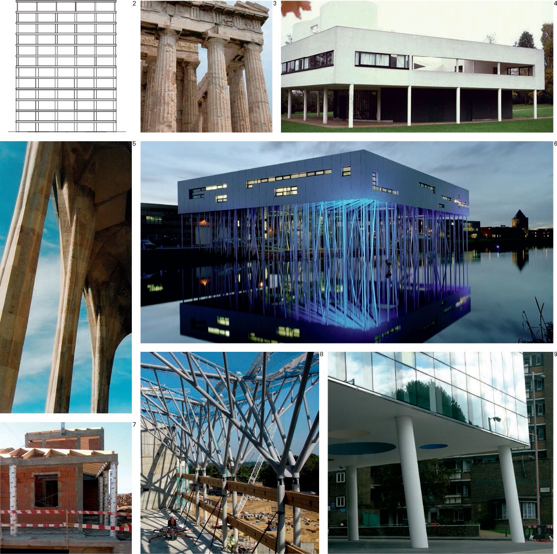
1 Cross-sections of columns. From left to right: four examples of solid columns, two of hollow columns and one H-section column.
2 Relative column sizes in a 26 ft 3 in square, 12-story tower.
3 The Parthenon, Athens, Greece. The stone columns are made in sections. They are Doric in style and are proportioned in the ratio of 6:1 – roughly the length of a man’s foot in relation to his height. They are 33 ft high, have a 5 ft 7 in diameter and are spaced at 13 ft centers.
4 Columns at Le Corbusier’s Villa Savoye built, in 1928, are made from 1 ft diameter reinforced concrete.
5 Stone columns at the Sagrada Familía church, Barcelona, Spain, by Antonio Gaudí.
6 The intervals between columns in a grid are directly related to their cross-sectional size. The Aluminum Knowledge and Technology Center (“The Aluminum Forest”), Utrecht, the Netherlands, by the architect Micha De Haas is supported by 368 aluminum tubes. The tubes are 19 ft 6 in high and have a diameter of between 3 ½ and 8 in.
7 Preformed tubes used as shuttering for circular section columns.
8 Branching columns at the Royal Ascot Racecourse, Windsor, UK, by the architects HOK Sport.
9 Inclined concrete columns at the Palestra building by SMC Alsop Architects. Angling and raking columns can help to brace a structure.
Bearing Elements / Foundations: Strip, Pad, Raft, Pile, Retaining Walls
See also: Bell Rock Lighthouse p146
Self-build House p164
Davies Alpine House p180

Foundations occur where structures carry loads to the ground. They are usually formed by filling holes dug into the ground with dense, massive material such as concrete or stone, or alternatively by driving rods – known as piles – into soft ground to the point where they become stable either through friction or through reaching down to bedrock.
Types
The stability and topology of the terrain will determine the type of foundation that is needed. Not only will the foundation prevent the structure sinking into the ground, it will also provide a stabilizing anchorage – a fixing. Shallow foundations (sometimes called spread footings) include strip footings, pads (isolated footings) and rafts. Deep foundations employ piles and retaining walls.
Shallow Foundations
For a bearing wall, a continuous or strip foundation is needed to support it throughout its length. An individual “point” load such as a column will require a pad or pile foundation. Raft foundations are used on unstable ground, and are so named because they act like a single, rigid element that “floats” on the terrain. Often it is necessary to use various foundation types in combination, for example a series of piles may be connected with a ground beam which acts like a strip foundation to carry a bearing wall.
Deep Foundations
Deep foundations are used where there is unstable terrain and are made by boring deep holes into the ground and inserting piles or piers. Piles can be made from a variety of materials such as timber, concrete and steel. Concrete piles may be precast or cast in situ and steel piles are usually either hollow tubes (pipes) or H-sections. Common, cast in situ concrete piles may be made either by pouring concrete into a drilled hole (which may contain steel reinforcement) or by driving a temporary or permanent steel casing into the ground and filling it with concrete.
Retaining Walls
When ground preparation also requires the excavation of material it may be necessary to form either temporary or permanent walls to hold back the surrounding terrain. This can be done using cast reinforced concrete (much in the way it is used for a swimming pool), interlocking sheet piles (profiled steel sheets that can be driven into the ground) or diaphragm walling which consists of a series of connected piles (known as secant piles).

1 Foundations/retaining walls. From left to right: strip, pad, raft, pile, retaining walls
2 To restrain a tensile load, either a friction anchor (similar to a tent peg) or mass is used.
3 Concrete cast in trenches to form strip foundations for a loadbearing wall.
4 Pad foundations carry loads at points.
5 A concrete raft foundation reinforced with a steel mesh. This will spread loads evenly over a surface.
6 Bored pile with steel casing. Concrete will be poured around the reinforcing bars.
7 Timber shuttering for a cast in situ, reinforced-concrete retaining wall.
8 Tensile connections to a concrete foundation.
9 Secant pile retaining wall. This is made by boring holes adjacent to one another and filling them with concrete. Excavation can then take place to reveal a series of “engaged” concrete piles (also known as contiguous piles). A vertical reinforcing mesh has been applied to the face of the secant piles; this will be sprayed with concrete to form a composite retaining wall with a continuous surface.
10 Sheet piles. Interlocking steel sheets are driven into the ground by a machine.
One-Way Spanning Elements / Beam: Cross-Sections

Beams are used as multiple, unidirectional spanning elements to carry floor and roof plates. Once a surface plate has been fixed to the beams, the whole floor or roof becomes a rigid (horizontally braced), structural element. Beams are described using a combination of their cross-section and linear profile.
Cross-Sections
The primary purpose of most beams is to resist bending forces. Bending induces compressive forces on the top of the beam and tensile forces on the bottom in a simple span from one element to another. The more beam material that is concentrated away from the member’s centerline, the more resistance to those forces that section will have. Therefore, beams should have a greater depth than width, and rectangular tubes or “I” shaped sections make more efficient use of material than solid rectangular sections.
Most beams maintain a consistent cross section across their span even though stresses vary in type and location in the beam along that length. Material may be used more efficiently by adjusting the depth or section of the beam in response to the stress that it receives at each point in its span. However, this is generally more expensive and is only done in specialized circumstances.
A beam-like spanning member used repetitively is referred to as a joist. Joists may be of many different materials and are generally lighter in weight than beams.

1 Cross-sections of beams. From left to right: four examples of solid beams, two of hollow beams and three of angled beams.
2 Extruded steel wide flange beam. The web resists bending and the flanges resist shear and torsion. Each flange tends to be between half and one-third the size of the web. Steel beams are specified according to weight per foot, area of section, and web and flange thickness. As a general rule, rolled steel sections have a span/total depth ratio of around 20 : 1.
3 The Parthenon, Athens, Greece. The span between the columns is only 7 ft 6 in, nevertheless this stone beam has cracked and been reinforced with metal pins to resist the tension low down in the beam. A beam that spans to form an opening in a wall is known as a lintel.
4 Wood roof joists. These are 1 ½ by 7 ½ in spaced at 2 ft on center. They span 14 ft 9 in. For average residential floors with joists spaced at 1 ft 4 in centers, the required depth in inches of a 2x joist is approximately half the span in feet plus two inches.
5, 6 Glued laminated timber beams (Glulam). Pieces of timber are glued together to create strong, versatile beams that can be shaped and curved. As a general rule, glulam beams have a span : total depth ratio of around 18 : 1.
7 Timber I-joists. These comprise a timber flange, typically solid timber and a panel product web, usually oriented strand board (OSB).
8 Glass: these structural glass beams comprise three pieces of ½ in. toughened glass laminated together.
9 Concrete T-section beams. Used in conjunction with smaller concrete slabs. As a general rule, rectangular section, reinforced-concrete beams have a span : total depth ratio of around 23 : 1.
10 Concrete box girder. Made up from precast concrete box sections; the upper flange acts as a deck.
11 Pneumatically-inflated air beams stitched together to form a canopy.
One-Way Spanning Elements / Beam: Linear Profiles
See also: Clifton Suspension Bridge p150

Linear Profiles
While a simple beam will maintain the same cross-section throughout its length, greater spans require the removal of material that is structurally redundant – material in the beam that is not working to carry loads – in order to reduce the dead load of the beam itself. This arrangement will tend to create deeper beams but (being relatively lighter) they are able to achieve long spans. Beams can be modified in this way by cutting holes in the web (as with a perforated or castellated beam) or by replacing a solid web with a series of vertical and diagonal struts (as with an open web truss; usually used for spans of over 50 ft.
Pure Tension
While compression structures commonly employ elements that are working in both tension and compression (see Forces: Stress, Strain, page 16), tensile structures also employ elements that are purely in tension. Long-span structures typically employ substantial tensile elements in order to reduce the dead loads to the minimum and are counterbalanced and anchored at each end.
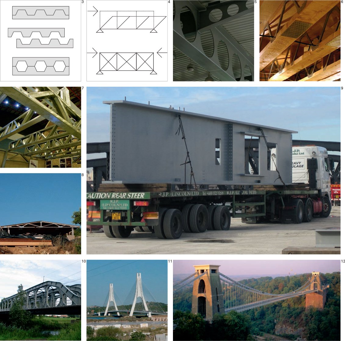
1 Linear profiles. Mainly compressive: solid beam, castellated beam, open web truss, and girder.
2 Linear profiles. Mainly tensile: bowstring truss, cable stay bridge, suspension bridge.
3 Process of forming castellated beams. Redundant material is removed from the web and, in the process, the depth of the beam is increased. These types of beam are capable of spanning up to 66 ft.
4 Open web trusses have diagonal cross-bracing to prevent them failing under eccentric load conditions. (Holed and castellated beams maintain triangulation in the body of the web.)
5 Perforated steel I-beams.
6 Composite open web joist: wood with steel connectors.
7 Open web trusses made from cold-rolled steel.
8 Open web truss as a pitched roof, known as a trussed rafter.
9 Plate girder. An I-section beam with a solid web composed of individual steel plates and vertical angles that are welded, bolted or riveted together.
10 Vierendeel truss. A truss that has no diagonal members but braces the frame using triangular connections at every junction between an upright and the top and bottom rails.
11 Cable stay bridge with cast-concrete masts. The platform is hung via cables that radiate from either side of the columns; the load is thus balanced through a double cantilever.
12 Clifton suspension bridge, Bristol, UK. Suspension bridges span long distances by hanging cables (in this case wrought-iron chains) between tall masts. The road decks are then suspended from vertical cables set at regular intervals.
One-Way Spanning Elements / Profiled Plate: Reinforced-Concrete Slab, Profiled-Sheet, Composite, Wafer/Laminate

In addition to beams, modern materials and methods of construction enable floors and roofs to be formed as single, monolithic plates.
Floor and roof plates that are formed as a single slab or “decking” can be designed to span either in one direction (one-way systems) or multi-directionally (two-way systems). There are two main ways of stiffening a one-way plate. One is to design in dropped beams to stiffen the plate and the other is to fold the plate into a corrugated profile.
As with a beam, a profiled slab or deck is a linear spanning element that maintains its cross-section throughout its length, but unlike a beam, it forms a continuous surface. Typically made from poured or cast materials such as concrete or plastic, profiled decks can also be formed using folded sheet metal – or by laminating profiled sheets around a core.
Span to Depth Ratio
As a general rule, the ratio of span to total depth for a continuous reinforced-concrete slab is around 32 : 1, and for a coffered slab, around 26 : 1. A steel space frame will have a span to depth ratio of around 15 : 1.

1 Folded plates. From left to right: reinforced concrete, profiled-sheet, composite, wafer/laminate.
2 Profiled metal sheets (metal decking) are used as permanent formwork and act partially to reinforce the in situ poured concrete.
3 Profiled metal decking is made from galvanized steel formed into a trapezoidal section.
4 Folded sheet. The principle employed for profiled metal sheets is used at a larger scale whereby spanning is achieved by casting a continuous concrete slab with a profiled or folded section.
5 Corrugated or profiled metal sheets are commonly used for small-span roofing.
6 Cast-concrete slab with embedded down-stand beams. These down-stands contain reinforcing bars so that the slab can resist tensile forces.
Two-Way Spanning Elements: Reinforced-Concrete Slab, Coffer, Space Frame, Wafer/Laminate

A two-way slab or deck is a surface that can act like a single, rigid element and be supported at a variety of points. These elements may be cast as a single component, such as a solid or coffered, reinforced-concrete slab. They may be formed by laminating sheets around a core (as in a wafer), or assembled using a framework of smaller elements as with certain types of coffer or as a space frame (also known as a space grid).
Space Frame
In the same way that a truss may be considered as a series of linearly connected triangles, a space frame is a grid of connected pyramids or tetrahedra. The relative lightness of this type of structure means it can achieve greater spans than other types of two-way spanning elements.
Span to Depth
As a general rule, the ratio of span to total depth for a continuous reinforced-concrete slab is around 32 : 1, and for a coffered slab around 26 : 1. A steel space frame will have a span to depth ratio of around 15 : 1.

1 Multidirectional spanning elements. From left to right: reinforced concrete, coffer, space frame, wafer/laminate.
2 Composite slab. A cast-concrete slab has an internal mesh of steel reinforcement to resist tensile forces.
3 Concrete reinforcement consists of steel bars joined loosely together to form a three-dimensional cage.
4 Cast-concrete slab showing the surface imprint of timber formwork.
5 Space frame. A lightweight, three-dimensional grid consisting of a series of linked pyramid shapes.
6 Coffered floor slabs.
7 By placing hollow plastic spheres and ellipsoid shapes within the steel reinforcement mesh, overall deadweight is reduced making larger, more efficient spans achievable.
8 Detail of plastic spheres in the steel reinforcement “cage”. These slabs are a 3D version of a castellated beam. Where the concrete is not carrying loads it is replaced with air.
9 Laminate. A slab can be made up of layers that are bonded together, such as this example of aluminum plates bonded to a honeycomb aluminum interior. Glass-reinforced plastic (GRP) may also be used to form structural elements by laminating foam cores with glassfiber-reinforced resin (yacht hulls are often made in this way).
10 Coffer. A 6 ft deep grid of welded steel girders forming the roof of the New National Gallery, Berlin, Germany by Mies van der Rohe; the 212 by 212 ft roof is supported by eight columns.
Connections and Joints: Dry Joint, Stone, Nail, Screw, Bolt
To understand how building components and building elements are assembled, it is necessary to explore the various methods of fixing and joining different materials.
Dry Joint: a pressure joint
The term joinery refers to the age-old tradition of connecting pieces of timber together to form a whole. Dry timber joints rely solely upon the precise geometry of the cuts made in the timber and the plasticity of the timber for a really close fit. Many connection types are possible. With a scarf joint, for example, the connection is designed so that two pieces of timber can be joined longitudinally, and so that the resulting element is able to resist tension, compression and torsion. To complete the joint, timber dowels (circular-section rods) are inserted into pre-drilled holes; in order to lock these dowels in position a hardwood wedge is cut to the same width as the dowel and then hammered into a saw cut.
Stone
Reference has already been made elsewhere in this book to drystone walls. Stone is cut and laid with an accuracy and in such a way as to rely solely on gravity for the integrity of the structure.
Nail: a friction joint
Nails are known to have been used to connect timber as long ago as the ancient Roman period. A nail is essentially a smooth shaft with a sharp point at one end and is typically made from steel. Nails are driven into wood by a hammer or a nail gun driven by compressed air. A nail holds materials together by friction in the vertical direction and shear strength in lateral directions. Nails are made in a variety of forms according to purpose; they can have a flat head to prevent them penetrating the surface of the wood or they may have a small oval head that will sink into the wood. Nails are normally cylindrical but “cut nails” (machine-cut from flat sheets of steel) have a rectangular cross-section. Common nails are known as wire nails.
Screw: a removable friction joint
A screw consists of a metal rod that has a head on one end and a continuous helical thread on the other that tapers to a point. The head may come in a variety of shapes according to function. However, all will contain a recessed groove or cross so that they can be turned using a screwdriver. A screw fixing relies on friction with the material into which it is bored and is most often used with wood.
Bolt: a removable connector
A bolt consists of a metal rod that has a head on one end and a continuous helical thread on the other. It is used in conjunction with a nut that contains the negative imprint of the thread. The bolt is passed through a pre-drilled hole in two or more objects and the nut is tightened over the protruding end. Both the bolt head and the nut are usually hexagonal in shape so that they can be turned using a wrench or spanner. Bolts are normally tightened to a precalculated load known as the torque load.
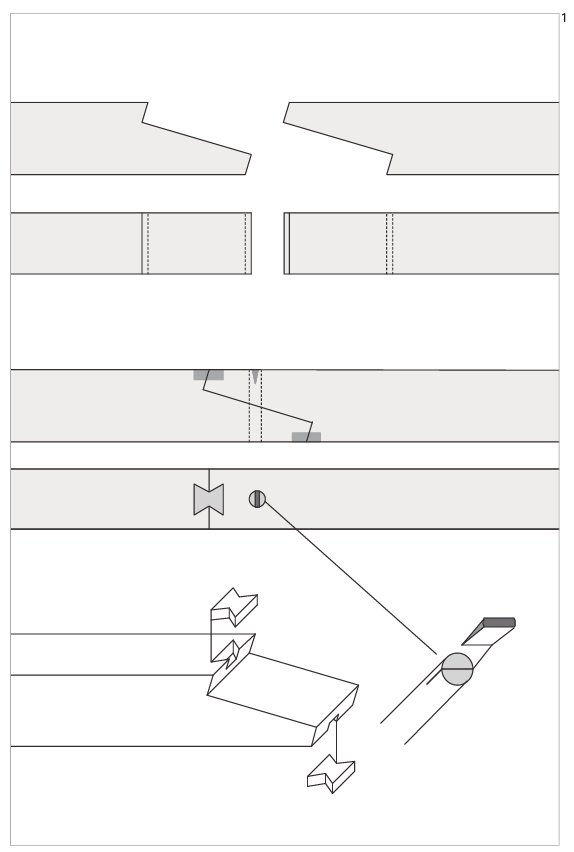
Firstly, the timber sections to be joined are cut to identical profiles; these are then connected on opposing faces using “butterfly” timber wedges; the whole assembly is then locked together using a timber dowel – the dowel is fixed by hammering hardwood wedges into grooves at either end.

1 Scarf joint assembly.
2 Common wire nail.
3 Woodscrew.
4 Basic bolt with a hexagonal head.
5 Dovetail joint.
Connections and Joints: Rivet, Turnbuckle, Adhesives (Glue), Welding, Brazing
Rivet: a one-sided joint
A rivet is a mechanical fastener. It starts off as a smooth cylindrical shaft with a head on one end. The rivet is driven into a pre-drilled hole so that the shaft becomes deformed and expands to about one and a half times the original diameter. Original “solid rivets” required two assemblers: one person with a hammer on one side and a second person with a bar on the other side. Unlike solid rivets, however, modern “blind rivets” can be inserted and locked into position from only one side of a structure. They are formed as a tube with a mandrel through the center, and a specially designed tool is used to draw the mandrel into the rivet, expanding the rivet and snapping the mandrel.
Turnbuckle: a tensioning mechanism
A turnbuckle is a device for adjusting the tension of ropes, cables and tie rods. It normally consists of two threaded eyelets, one with a left-hand thread and the other with a right-hand thread, both screwed into each end of an extruded nut. The tension can be adjusted by rotating the nut, which causes both eyelets to be screwed in (or out).
Adhesives (Glue)
An adhesive is a liquid compound that bonds two items together and may come from either natural or synthetic sources. There are adhesives that can be used on almost any material or combination of materials. Adhesion may occur either by mechanical means, where the liquid adhesive penetrates into the material and then hardens, or by one of several chemical mechanisms. The first adhesives came from plants (resins) and animals (fat).
Welding
Welding is the only way of joining two or more pieces of metal to make them act as a single piece. With welding, metals are joined by applying heat, sometimes with pressure and sometimes with an intermediate, molten filler metal. By applying intense heat, metal at the joint between two parts is melted and caused to intermix. Once cool, welds can be ground flat using an abrasive wheel. The most common methods for fusing metals in this way are arc welding and metal inert gas (MIG) welding. With arc welding, the intense heat is produced by an electronic arc. The arc is formed between the metal and an electrode (rod or wire) that is manually or mechanically guided along the joint. Often, the rod or wire not only conducts the current but also melts and supplies filler metal to the joints. With MIG welding, an aluminum alloy wire is used as a combined electrode and filler material. This semi-automatic process feeds a continuous spool of filler wire to the weld bead by magnetic force – a process known as spray transfer, which enables welding from any position.
Brazing
While in welding the metal of the joining surfaces is fused by melting, brazing requires the joining surfaces to be heated, but only the filler material to be melted. The filler metal has a lower melting point than the metal(s) to be joined. It joins by bonding rather than fusing. It generally employs lower temperature than would be required to join the same materials by welding. More accuracy is required with brazed joints than with welded connections. However, if the geometry of the faces to be mated is well matched a brazed joint will be stronger than the parent metal.

1 MIG-welding aluminum sheet metal.
2 Arc-welding structural steelwork.
3 Bolted steel connection.
4 A “blind rivet”.
5 A “reverse threaded” turnbuckle.

Structural logic taxonomy chart. Red lines indicate bracing elements.