
Origins of Construction Types
The following range of case studies illustrates the historic relationship between design and technology in architecture and civil engineering. The examples are listed chronologically. Generally, the older the structure, the more likely it is to be low tensile in nature – the materials used are largely in compression and are therefore unsuitable for long spans. At the same time, older structures were not necessarily less environmentally efficient than modern ones, and it can be seen that passive environmental control was inherent in much traditional, vernacular architecture. Traditional dwelling types were born out of the local environment – both making use of its physical resources and reacting to its climate. Whether it was trees, rocks, mud or snow, each material has found a way to be employed as both structural form and climatic envelope. The first reliable traces of human dwellings, from as early as 30,000 years ago often consisted of a circular or oval ring of stones, with evidence of local materials being used for a tent-like roof. In wet areas, such materials may have been reeds daubed with mud or, in the open plains, mammoth bones and tusks lashed together to support a covering of hides.
Size
Although the circular plan worked as an efficient generator of structural form for many materials and construction methods, tall and long-span structures really began to develop with advances in materials science and industrial processes that were often pioneered in the transport industries. Knowledge from the shipbuilding, automobile and aerospace industries, where the need for strength and lightness has been paramount, was adapted and transferred for use in construction technology. Chain and wire rope, for example, not only enabled the construction of suspension bridges, but also that of lifts without which there would be no skyscrapers.
Prefabrication
Off-site manufacturing, the ability to fabricate building elements in the controlled environment of a factory or workshop, has long been known to result in better quality control. With the advent of the Industrial Revolution, the capacity to transport ever larger components has progressively expanded the possibilities for prefabricated building elements. The ultimate expression of this is the international space station whose parts are delivered in the hold of a space shuttle.
Note: Icons in the case studies cross refer to the main technical elements used in the construction of a structure or building, and also indicate where thermal comfort, air movement, and acoustics have been major factors in its design.

Location: Middle East
Date: From 8000 BC
Height/Diameter: Varied
Materials: Mud bricks
Evidence of bricks shaped from mud and baked hard in the sun can be found as long as 10,000 years ago. The houses were circular in plan and built with bricks that were curved on their outer edges. The floor of each house was excavated some way down into the ground, and then both the floor and the brick walls were plastered in mud. The roofs consisted of a conical structure of branches and mud (wattle and daub). Later, around 6500 BC, there is evidence of roofs in the form of domes that had been built up by stepping (“corbelling”) the brick courses towards the center – a technique that had its ultimate expression in the Pantheon in Rome some 6,600 years later.
Mud Bricks
A mud brick is an unfired brick made of clay. Usually found in hot climates where there was a lack of timber to fuel a kiln, they were dried in the sun and had a lifespan of no more than 30 years. The Great Mosque of Djenné, in central Mali, is the largest existing structure made from mud bricks.
Adobe
This is a type of mud brick still used today. It is generally used as a bearing system and provides good thermal storage and insulative qualities. Clay and straw are mixed together and pressed into mold to make adobe.
Rammed Earth
Rammed earth construction is a process of compressing a damp mixture of earth (consisting of sand, gravel, and clay, sometimes with an added stabilizer) into a mold (known as the formwork) in a similar process to that of casting reinforced-concrete walls. Traditional stabilizers included lime or animal blood, but modern rammed earth walls usually employ a cement additive. After compressing the earth, the formwork can be immediately removed but the earth will require a period of warm, dry days to dry and harden. Rammed earth walls can take up to two years to cure completely, but once the process is complete they can be readily nailed or screwed into, and they are good thermal and acoustic insulators.

1 A mud house fabricated from dried earth bricks. Wadi Azzan, Shabwah, Yemen.

Location: North America
Date: From 4000 BC
Height/Diameter: Varied
Materials: Timber sapling, animal skin
Engineers: Native American Indians
A tepee is a conical tent originally made of animal skins and popularized by the American Indians of the Great Plains from around AD 1700. The skins were both good insulators and remained dry during heavy rain. Importantly for these nomadic tribes, the tepee was portable.
Tepees were traditionally built using between 10 and 20 sapling poles, with an animal skin cover and sometimes an inner lining for ventilation and/or extra insulation. Initially, three poles would be lashed together at one end and erected to form a tripod-like frame. Other poles were then to form a circular shape at ground level and all the poles were then bound together. Once the skins had been attached to the poles, the non-tripod ones were pulled out at ground level in order to complete the tensioning of the whole structure and the skins were pegged to the ground. This anchoring system, combined with the conical shape of the tepee, made it highly resistant to wind load.
Tepees are different from other tents in that there is an opening at the top with flaps that can be adjusted with long poles. When open, the flaps are set at angles to prevent the prevailing wind entering the tent while at the same time enabling the tepee to act like a chimney and so allow for an open fire to be lit within. An inner lining strung from the poles about 5 ft above the ground could be used either to shut off drafts or to direct the flow of incoming air so as to feed the fire or supply fresh air to the tepee’s occupants. In hot weather, the lining would be removed and the outer skin would be unpegged and rolled up to encourage cross-ventilation.
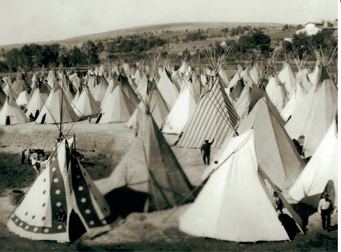
1 Typical native American Indian tepees.
Igloo

Location: Central Arctic, Greenland
Date: From AD 1000*
Height/Diameter: Varied
Materials: Snow
Engineers: Inuit
An igloo, also spelled iglu, is constructed from blocks of snow in the form of a dome. The dome can be raised by stacking blocks of compacted snow without any supporting structure: blocks are cut to shape with a snow saw or large knife and stacked in a helical fashion. Each block is a rectangle measuring about 24 by 48 by 8 in; the best snow to use is from a deep snowdrift of finegrained snow that has been blown by wind, which compacts the ice crystals. Joints and crevices are filled with loose snow and a clear piece of ice, or seal intestine, is inserted for a window. If correctly built, an igloo will support the weight of a person standing on the roof.
Like animal skins, snow has a low density and is thus a good insulator. While temperatures on the outside may be as low as –49ºF, the inside temperature can range from 19ºF to as much as 61ºF when warmed by body heat alone. In the traditional Inuit igloo, heat from a stone lamp would cause the interior to melt slightly and this melting and refreezing built up an ice sheet and contributed to the strength of the structure.
Igloos are entered via a narrow, semicylindrical passageway about 10 ft long that is sunk into the snow and which then penetrates the igloo through a hole beneath the wall. This allows cold air to exit as the igloo warms up. A raised sleeping platform is constructed in the warmer, upper part of the dome. The Central Inuit line the living area with animal skins, which can increase the temperature within from around 35ºF up to 50–70ºF by increasing heat retention.
It is vital to make at least one air hole in the roof of an igloo to avoid suffocation, since without ventilation lethal carbon dioxide will build up. An experienced Inuit can build a snow igloo in between one and two hours.
*It is not known when or where the igloo originated, but it is known that the Inuit first migrated to what is now northern Canada roughly 1,000 years ago. These Inuit were descended from Palaeo-Eskimo people who first appeared in western Alaska between 5,000 and 4,000 years ago.

1 Constructing an igloo. After the first row of blocks has been laid out in a circle on a flat stretch of snow, the top surfaces of the blocks are shaved off in a sloping angle to form the first ring of a spiraling helix. It is believed that the helical shape aids in the construction process as successive blocks can lean on each other.
2 A computational fluid dynamic (CFD) model of an inuit igloo, showing the effects of ventilation flows and retained heat.
Location: Karnak, Egypt
Completion date: 1450 BC
Height/Weight: 97 ft/350+ tons
Materials: Red granite
Engineer(s): Ancient Egyptians
Standing stones (or megaliths) were the product of mankind’s first attempts to build tall, slender structures. They are often presumed to have been used as clocks (to cast shadows as with a sundial), and very little is known about the techniques used to erect them. However, there are records that show how the ancient Egyptians made their obelisks.
Often referred to as needles, obelisks were designed to stand at either side (east and west) of the entrance to a temple, to represent the rising and setting of the sun. Much of the granite used for these megaliths was quarried from the hills around Aswan in southern Egypt.
It is not known how the ancient Egyptians could predict that there would be perfect unbroken slabs of granite at the precise locations they chose. However, it is thought that they would have dispatched holy men (seers) to establish where to quarry. Indeed, there is an unfinished obelisk in the hills just outside Aswan that must have developed a crack during the digging of the trenches. It is the strongest piece of evidence for the excavation techniques used and would have been the largest and heaviest of all the obelisks by some margin.
Once a site had been chosen, fires were lit to burn off the foliage and loosen the topsoil.
The rough shape of an obelisk was then marked out and labourers, working in pairs, commenced digging two parallel trenches on each side of it, using dolomite balls attached to sticks in a hammering action. Hundreds of labourers would chant (for rhythm) as they worked, and once the trenches were of sufficient depth, they would tunnel underneath the granite, propping it with lumber as they progressed. After many months, the obelisk would be freed from the ground. It would then be levered out using rough timber logs and transported from the hills above Aswan down to the river Nile where it was placed on a barge. From here it may have travelled as far as Cairo, 400 miles downstream.
Once on-site, the finishing work was carried out. The obelisk carved into a tapering shape in order to lower its center of gravity, the surface of the granite was smoothed, polished and carved with intricate hieroglyphs, and finally the megalith was capped with gold. It is still not known how an obelisks was erected. However, it was placed on a plinth that was dug into the ground to act as a foundation stone.
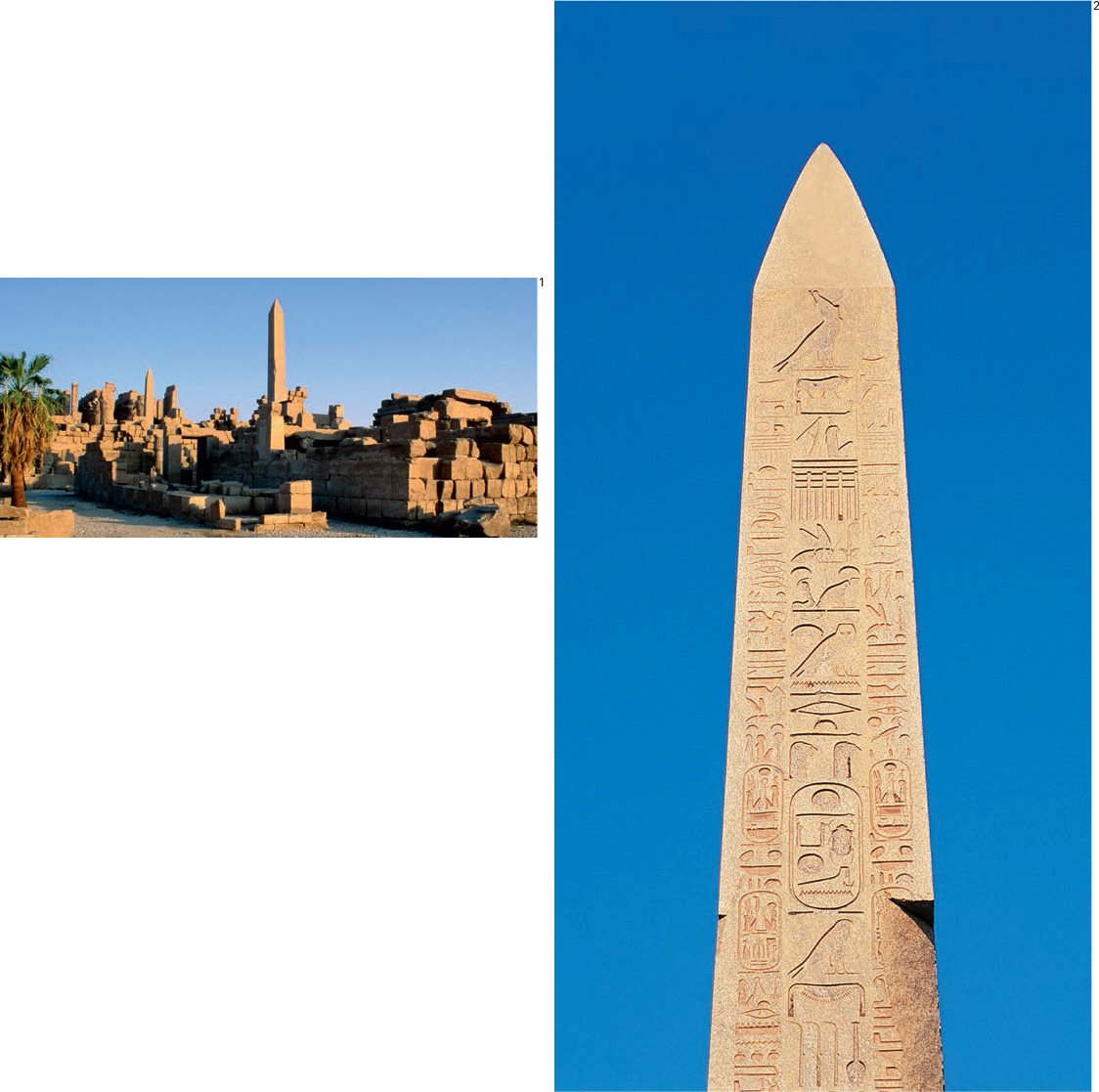
1 View of the obelisk in situ at Karnak.
2 Detail.

Location: Rome, Italy
Completion date: AD 126
Span/Weight: 142 ft/5,000 tons
Built by the emperor Hadrian, the Pantheon was the largest dome in the world until Brunelleschi’s dome in Florence in 1436. The dome was built using stepped (coffered) rings of concrete that diminished in both density and thickness as it rose from its base, where it is 21 ft thick, to the oculus where it is approximately 41 ft thick. The dome sits on a cylinder of 21 ft thick masonry walls, which are constructed with a set of eight barrel-vaulted voids and recesses lined with travertine. Although the dome was built with cast concrete, it was not in any way reinforced and still holds the record for the largest unreinforced concrete dome in the history of architecture.
The precise composition of the concrete is not known. Typically, Roman concrete was made from a mix of hydrate of lime, ash, pumice, and pieces of solid rock. However, as there were no reinforcing bars to resist the tensile stresses, it can only be assumed that their concrete was both lighter and better compacted than its modern-day equivalent.
The dome of the Pantheon has a 27 ft circular opening to the sky at its center, which illuminates the vast interior. This oculus also serves as a cooling and ventilation method. As wind passes over the dome it is accelerated, and creates a negative pressure zone that sucks air out from the top of the dome and forces fresh air to be drawn in from the entrance to the Pantheon. The oculus was edged with a circular bronze cornice, which is still in place. The exterior of the dome was originally covered in gilded bronze plates, later replaced by lead.
The internal height of the Pantheon precisely matched that of its diameter in plan, so an imaginary sphere can be envisaged alluding to the cosmos, with bronze stars originally decorating the coffered ceiling and the oculus representing the sun at the center of the universe.
The ceiling of the dome is lined with five horizontal bands of coffered panels that decrease in size toward the top. The moldings of each band are foreshortened to control their appearance from below. The coffered panels reduce the overall deadweight of the ceiling as well as providing decoration. They are lined with marble and porphyry stone.
The portico of the Pantheon measures 110 ft wide by 59 ft deep and features 16 monolithic (one-piece) granite columns imported from Egypt. Each column is 46 ft high with a diameter at its base of 5 ft; this reduces to a diameter of 4 ft 3 ½ in at the column top. Each column weighs an estimated 60 tons. The huge bronze entrance doors and fanlight were originally plated with gold.
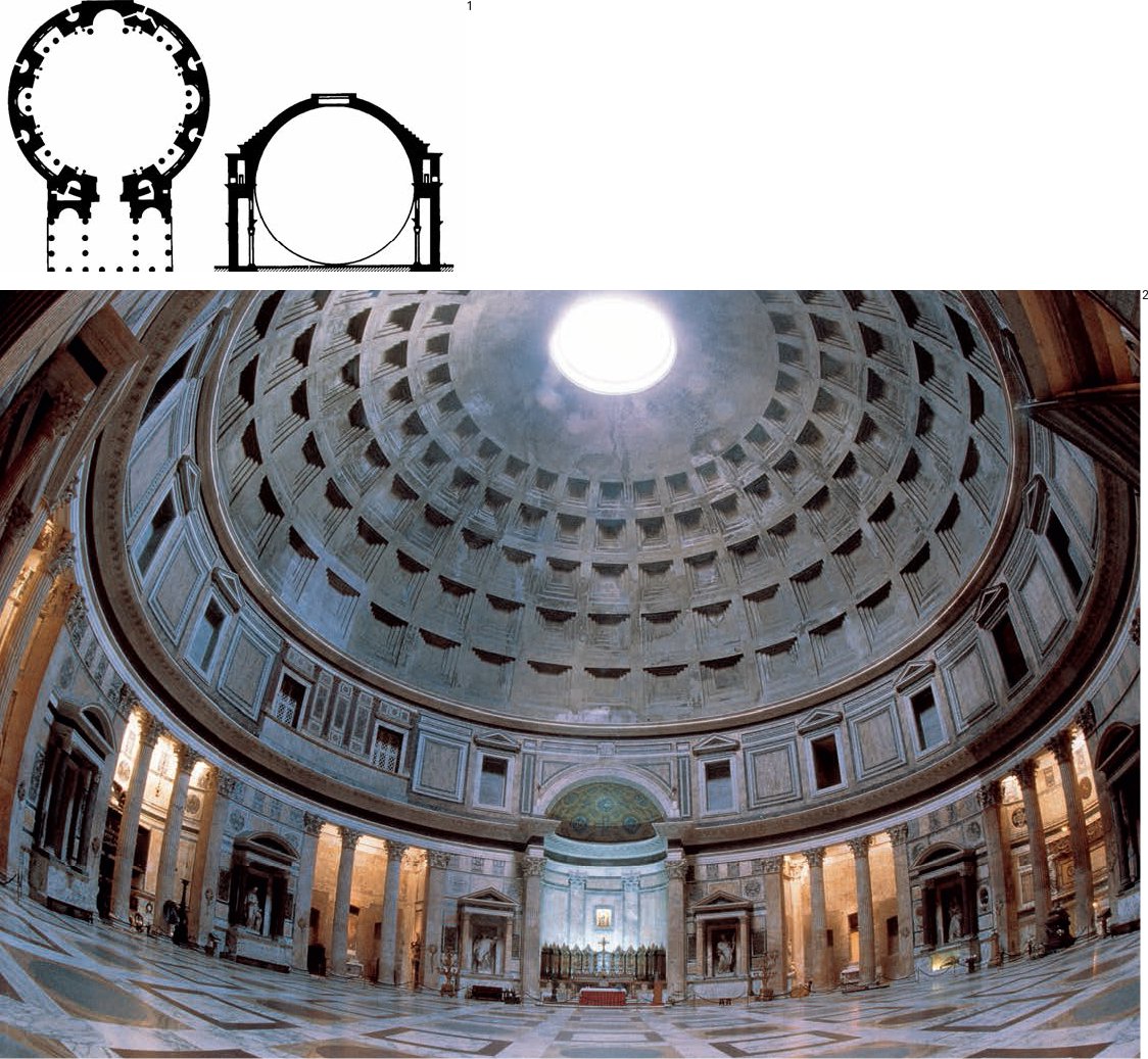
1 Plan and cross-section of the Pantheon. The building’s interior dome and supporting drum contain a perfect sphere.
2 View of the interior.

Location: Severn Gorge, Coalbrookdale, UK
Completion date: 1781
Length: 100 ft
Materials: Cast iron
Engineers: Abraham Darby III, Thomas Farnolls Pritchard
The Ironbridge at Coalbrookdale in Shropshire, England, was the first bridge (or indeed civil engineering structure) in the world to be made entirely of cast iron. East Shropshire was an important industrial area thanks to coal deposits near the surface, and it was here that the Industrial Revolution was born.
The project was initiated in 1775, when a group including Abraham Darby III, Thomas Farnolls Pritchard and John Wilkinson became interested in creating a physical link between Coalbrookdale and the mines, foundries and quarries south of the Severn River. Thomas Pritchard (an architect) was awarded the job of designing the bridge and in 1777 it was agreed that Darby should build the new bridge with a span of 90 ft. However, Pritchard died later that same year leaving Darby the job of building this extraordinary structure. In 1778 the bridge abutments were complete and in 1779 the giant iron castings were fabricated. The first two ribs were installed in July with each weighing 5.5 tons, and by the fall the main iron superstructure was complete.
The final completion was considerably later, in 1781, after the approach roads were finished. The bridge had a far-reaching impact: on local society and the economy, on bridge design and on the use of cast-iron in building.
Its arch finally spanned 100 ft, and has five arching ribs, each cast in two halves. Although the bridge is made from iron, the construction details were adapted from traditional timber construction, which Darby’s workers would have been used to employing. Blind dovetailed joints, where only half the thickness of the iron is in the shape of a dovetail, join the arched ribs to the radials, while mortise joints secured by wedges secure the ribs to the horizontal and vertical members at each end of the bridge.
All the major components were put together in three months without a single accident or the least obstruction to the boats on the river. It is likely that a timber scaffolding would have been employed as a temporary support during the erection of the ribs and to create a temporary span for river traffic to pass beneath.
In the great flood of the Severn in 1795 the Ironbridge was the only bridge left undamaged, which only added to its status as a marvel of contemporary engineering and an advertisement for the possibilities of metal structures.
The completion of the bridge marked out Ironbridge Gorge as one of the most technologically advanced areas in the world at the close of the eighteenth century. This achievement was given worldwide recognition when, in 1986, the Ironbridge Gorge became the first of seven United Kingdom sites to be awarded World Heritage status by UNESCO, to celebrate the area’s contribution to industrialized society.

1 Diagram of the blind dovetail joinery that connects the arched ribs to the radials.
2 View of the Ironbridge.
Location: Scotland, UK
Completion date: 1811
Height/Weight: 115 ft/2,296 tons
Materials: White sandstone and Edinburgh granite
Engineers: Robert Stevenson with John Rennie
The lighthouse was built at a time when increasing international trade meant that many sailors’ lives were being lost around the treacherous coasts of Europe. It was built 11 miles out to sea on the east coast of Scotland in the northern reaches of the great sea estuary known as the Firth of Forth, on a reef which, except at low tide, lies submerged just beneath the waves. It was constructed with no power except for men and ponies.
The design of the lighthouse was the culmination of knowledge gained from the construction of previous lighthouses (many of which failed) and from prototyping with scale models. John Smeaton had built the Eddystone lighthouse in 1759, pioneering the use of stone. Not only were the stones dovetailed to interlock with one another but were reinforced vertically with posts (similar to the dowels in a scarf joint).
The ideal profile to resist the enormous impact from wind and waves was found to be parabolic in shape. The Bell Rock lighthouse had a broader base than some of the earlier designs, the theory being that, to minimize the action of the sea against a solid tower in such an exposed situation, the sea’s force would be better deflected with a shallower rise from the base than if a tower took off at a steeper angle. The first course has a diameter of 42 ft and each of its stone blocks weighs more than a ton.
One of the first things that had to be done was to prepare a vessel to act as a “floating light” – a novel idea at the time – that would be moored just off the rock. Secondly, a beacon house (a temporary structure that would eventually house the builders) was to be built on the rock. The “Smeaton,” named in honor of John Smeaton, was built to act as a tender for the floating light and to transport the blocks of stones from the harbor out to the Rock. Stones had to be transferred from the “Smeaton” to smaller boats and then by special winching tackle onto the rock.
The Bell Rock was submerged twice daily to a depth of sometimes 16 ft, and on average it was only possible to work it about two hours every low tide. In all, 2,835 stones were used in the construction of the lighthouse and the stonework has never needed any kind of repair.

1 Plan of the lighthouse’s interlocking foundation stones.
2 Cutaway illustration of the Bell Rock lighthouse under construction.
Location: London, UK
Completion date: 1851
Area: 1,848 x 454 ft
Materials: Iron and glass
Engineer: Joseph Paxton
The Crystal Palace was designed to house 100,000 exhibits for the Great Exhibition of 1851. The first international exposition of its kind, it was conceived by Queen Victoria’s consort, Prince Albert, in order to celebrate technology from around the world at the height of the Industrial Revolution.
Paxton’s design was based on his experience of designing greenhouses, which were in turn said to be influenced by the structure of the Amazonian water lily – radial ribs, strengthened by slender cross-ribs. These principles produced a lightweight structure that was also capable of using prefabricated components – the first of its kind. It was made from “ferro-vitreous” iron, timber and glass, and the dimensions of the structure were based on the largest sheet of glass that could be manufactured at the time.
One of the major advantages of Paxton’s ferro-vitreous iron-and-glass design was the building’s extreme simplicity – all the principal elements of the building were arranged in multiples and sub-multiples of 24 ft. The total height from the ground floor to the top of the barrel-vaulted transept roof was 108 ft. The transept was added to the design to help enclose some 90 ft-tall elm trees. In total 900,000 sq ft of glass was used, and the entire structure was demounted from its first site in Hyde Park and reconstructed in south London.
The heights of the columns ranged from 16 ft 9 in to 18 ft 4¼ in, with the taller versions on the ground floor. Each column was formed of four flat and four cylindrical faces, and the external diameter of all the columns was 8 in on their square face. The base of each column was fixed to a flat plate 2 ft in length and 1 ft in width. This in turn was fixed to a mass of concrete with a length and width of 2 ft by 3 ft and varying in depth from 1 ft to 4 ft.
There were nine varieties of girders and trusses, each 3 ft in depth. There were three different strengths of 24 ft cast-iron girders, one strength of 24 ft wrought-iron trusses (wrought iron was used for its tensile strength), one strength of 48 ft wrought-iron trusses and three strengths of 72 ft wrought-iron trusses.

1 Floor plan of the Crystal Palace.
2 View of the Crystal Palace, c. 1930.

Location: Bristol, UK
Completion date: 1864
Length: 702 ft
Materials: Masonry and steel
Engineer: Isambard Kingdom Brunel
When constructed, the Clifton suspension bridge was the longest single-span bridge in the world. It spans 702 ft, measured from the center of each pier, over the 250 ft-deep Avon Gorge. Although Brunel was 24 when he won the competition to design the bridge, it was only completed five years after his death in 1859. Brunel’s colleagues in the Institution of Civil Engineers felt that completion of the bridge would be a fitting memorial; in 1860, Brunel’s Hungerford suspension bridge over the Thames in London was demolished to make way for a new railway bridge and its chains were purchased for use at Clifton.
Brunel was born in 1806, and by the 1820s was working with his father on the early stages of the construction of a tunnel under the Thames. In 1833, he was appointed chief engineer of the new Great Western Railway and went on to create innovative designs for everything from tunnels, railways and bridges to harbors, prefabricated buildings and ships. Brunel was always on the lookout for new technologies (in particular expanding the use of iron) and revolutionized society’s approach to both mechanical and structural engineering. The piers (towers) of the Clifton suspension bridge are built principally of local Pennant stone. The 86 ft high tower on the Leigh Woods side of the Avon Gorge stands on an abutment that was originally thought to have been solid but has since been found to consist of a series of 12 vaulted chambers linked by small tunnels. The wrought-iron chains from which the deck is suspended dip to 70 ft and are anchored back into the rock at either end through tunnels that are 60 ft below ground level. Roller-mounted “saddles” are used at the top of each tower to absorb the forces created by the movement of the chains when under load.
The road deck itself is carried by two, huge girders (assembled in sections each of which was connected to the chains using vertical suspension rods) and is made from 5 in thick pine beams (known as sleepers) with 2 in thick floor planks. In total, the bridge used 1,600 tons of steel.
The bridge was designed to carry horsedrawn traffic but now carries 11,000 to 12,000 motor vehicles every day.

1 The Clifton suspension bridge, Avon Gorge.
2 Detail of connections between the deck and the wrought-iron chains. The road deck is suspended from the chains by 81 wrought-iron rods on each side, which range from 65 ft in length at the ends to 3 ft in the center.
Tropical House (Pavilion Demontable)
Location: Brazzaville, Congo, Africa
Completion date: 1951
Area/Weight: 1,600 sq ft/11 tons
Materials: Sheet steel, aluminum
Engineer: Jean Prouvé
Jean Prouvé was a trained locksmith who pioneered design and fabrication processes for furniture and modular construction. His prototype lightweight, prefabricated metal building system represented a major step in the industrialization of architecture.
Fabricated in Prouvé’s French workshops, the components for two modular buildings, designed in collaboration with his brother Henri, were completed in 1951 and flown to Africa in the cargo hold of an airplane. The houses are designed on a simple, 3 ft 3 in, grid system and consist of a series of ground beams connected to fork-shaped portal-frame supports of folded sheet steel. Prouvé’s unique portal frame system provides horizontal bracing to the entire structure and support for the roof and walls, enabling the wall panels to be kept as light as possible. All but the largest structural elements are aluminum, and no piece is longer than 13 ft – which corresponds to the capacity of the brake press (folding machine) – or heavier than 200 lb, for easy handling by two men.
The fabrication of the portal elements and other structural components was, and remains, an innovation in the construction industry, utilizing sheet-metal techniques of folding, pressing and profiling to get maximum strength out of a light and flexible substrate. In techniques more often employed in the automotive and aeronautical industries, Prouvé pioneered a prefabricated, component-based approach to construction that remains highly influential within the profession and can clearly be seen in the English hi-tech movement of the late twentieth century (Norman Foster, Richard Rogers et al). Interestingly Jean Prouvé was one of the jury members on the judging panel for the Centre Pompidou, Paris, won by Renzo Piano and Richard Rogers. The structural integrity of Prouvé’s system meant that the building could be propped up or supported by a series of designated columns locally prepared in advance of their arrival, which deals with both ventilation and potential damp. Again, this technology is more akin to that of a vehicle, be it a plane, train or automobile and shares the technological ambition of Buckminster Fuller’s Dymaxion Dwelling Machine (or Wichita House) of 1946.
To cope with the extremes of the tropical climate, the outer light-reflecting skin, consisting of adjustable brises-soleils of each building that shielded the structures from direct sunlight, was separated from the inner insulated skin of sliding doors and fixed panels. The buildings used self-shading natural cooling and ventilation with the profile of the roof “wings” designed to exploit the stack effect, thus cooling the structures.
In 2001, one of the buildings (pockmarked by bullet holes) was brought back to Paris, and was restored and reassembled. It has subsequently been moved to the USA where it was put on sale by Christie’s, as part of a contemporary design auction and sold for the not inconsiderable sum of US$6 million. The eventual economic value of this highly prized prefab could not have been envisaged by Prouvé, but the ease of relocation most definitely was.

1 Rotating louvre used in the construction of the Tropical House.
2, 3 Interior views of the Tropical House as reconstructed.

Location: MIT campus, Massachusetts, USA
Completion date: 1955
Height: 50 ft
Span: 160 ft
Materials: Reinforced concrete
Architect/Engineers/Acousticians: Eero Saarinen, Ammann & Whitney, Acentech
Eero Saarinen designed the Kresge auditorium together with the MIT chapel; the two buildings are separated by a green space. The ensemble is recognized as one of the best examples of mid twentieth-century modern architecture in the USA. This was Saarinen’s first major public project, but despite its architectural success there was a perception that it was an unsuccessful piece of civic design. Saarinen himself later remarked that the two inward-orientated structures were “too egotistical... theoretically, it is a very graceful building. Structurally, it’s quite a rational building. But, if you look at it, isn’t it a little bit too earthbound? ... It did not have the soaring quality or sense of lightness that one wanted.”
The reinforced-concrete shell structure takes the form of a one-eighth segment of a sphere, and is supported at three points by concrete and steel abutments. Triangular in plan, the roof is clad in copper, and steel-framed glass walls complete the climatic enclosure. Although the first double-curving, lattice structure (grid-shell) had been built out of steel sections as far back as 1897 (by V.G. Shukhov), thin, reinforced-concrete shell structures were still largely experimental at the time, and the roof weighed only 1,200 tons. The Kresge auditorium was the first (thin) concrete shell of this size in the USA. The dome touches the ground at three points almost 150 ft apart and is only 3½ in thick at its uppermost point.
The building was designed to be an auditorium with seating for 1,226 people. As it is a column-free space, each person has an unobstructed view of the stage area. The acoustic quality of the space was controlled by the innovative use of free-hanging ceiling baffles that could absorb and direct sound. In 1998, as part of a general refurbishment, the acoustic quality of the space was further enhanced by new acoustic panels that were designed to reflect some of the sound back to the stage and spread the rest as uniformly as possible.
There has been much speculation that the design of Saarinen’s subsequent TWA Terminal Building at Kennedy International Airport, New York, may have been influenced by Jørn Utzon’s winning entry for the Sydney Opera House competition, for which Saarinen was a jury member (see page 166). Conversely, it might be that Utzon was influenced by the then constructed shell of the Kresge auditorium, completed in 1955.
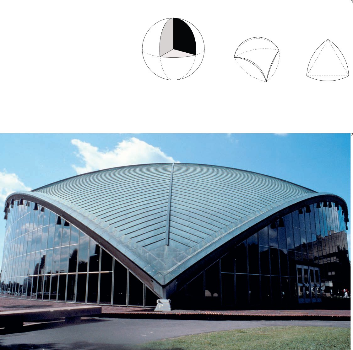
1 Diagram showing the one-eighth segment of a sphere that makes up the shell structure.
2 View of the auditorium.

Location: Rome, Italy
Completion date: 1959
Materials: Reinforced concrete – ferrocement
Dimensions: diameter 194 ft, height 69 ft
Engineer: Pier Luigi Nervi
Known as a lamella dome, the palazetto was built from reinforced concrete for the 1960 Olympic Games. The 5,000-seat “little palace” (designed with Annibale Vitelozzi) has prefabricated diamond-shaped sections that fit together to form transversing helical ribs. The dome springs from a series of exposed, prefabricated Y-shaped piers sloped to receive their diagonal thrusts. These piers allow for large openings at ground level.
Nervi was an engineer and building contractor who became internationally famous for his invention of ferrocement – a dense concrete heavily reinforced with steel mesh. Between 1935 and 1942, he designed a series of aircraft hangars for the Italian air force, the first of which at Orvieto (1938) determined their form: long, pointed barrel vaults, constructed on latticed grids, rising from complex triangulated edge-beams. The various-sized ribs were prefabricated from reinforced concrete rather than being poured in place. Instead of using traditional methods for reinforcing concrete, Nervi designed a more balanced, composite material consisting of layers of steel mesh grouted together with concrete. He also pioneered the use of prefabricated concrete panels, thus avoiding costly and time-consuming timber formwork.
In addition to designing large-span vaults and domes, Nervi succeeded in building a sailing boat with a ferrocement hull only 1⁄2 in thick.
The Palazzetto Dello Sport is still in regular use, mainly for Basketball. Also in Rome’s EUR (Esposizione Universale Roma) district is the much larger, Palazzo Dello Sport, also by Nervi.
Pier Luigi Nervi won the Royal Institute of British Architects (RIBA) Gold Medal in 1960.
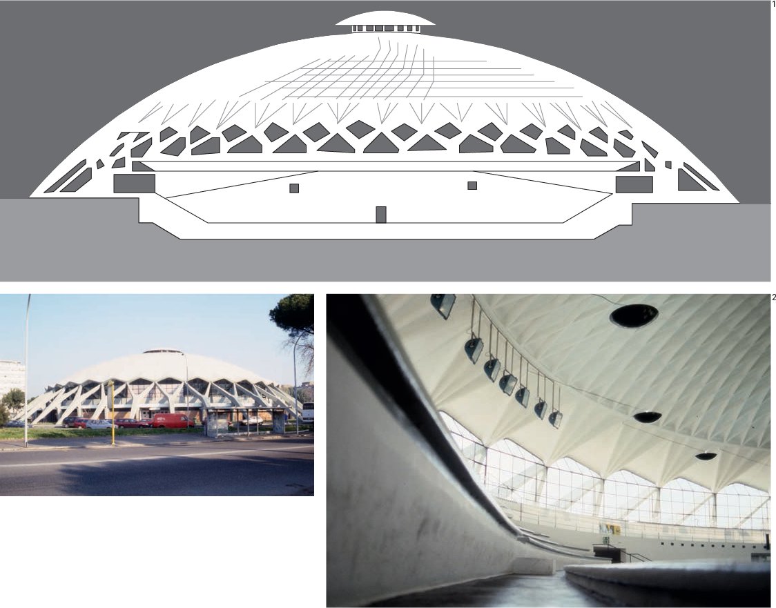
1 Cross-sectional drawing of the Palazzetto dello Sport, Rome.
2 Exterior and interior views of the Palazzetto Dello Sport.

Location: Houston, Texas, USA
Completion date: 1965
Height: 208 ft
Weight: In excess of 2,700 tons
Materials: Concrete and steel frames
Architects: Hermon Lloyd & W.B. Morgan and Wilson, Morris, Crain & Anderson
Structural Engineers: Walter P. Moore Engineering Consultants
The Astrodome was the first ballpark/ stadium to have a roof over the playing field. The dome has a clear span of 642 ft and is constructed with trussed ribs that are 5 ft deep. The roof, which covers an area of 350,000 sq ft, is held in place by a 414 ton tension ring. An 18-story building would fit inside the Astrodome.
The stadium seats up to 66,000 people, and the central air-conditioning system has to circulate 2.5m cu ft of air a minute.
The Astrodome was also designed with an astonishing 28,000 car parking spaces over a site of 280 acres.
The Houston Astrodome marked what many saw as the birth of modern stadium design. It represented the first totally enclosed multi-purpose stadium in the world. In three configurations the Astrodome can seat 66,000 spectators for concerts, 52,000 for American football and 45,000 for baseball.
When the Astrodome opened the playing surface was natural Bermuda grass. The dome’s ceiling contained numerous semitransparent plastic panels made of Lucite. Players soon complained that glare coming off the panels made it impossible for them to track “fly balls,” so all the panels were painted over – which solved the glare problem but caused the grass to die from lack of sunlight. This led to the development of a new artificial playing surface that used a synthetic woven “grass” matting, which was subsequently named Astroturf after its originating venue. The Astrodome was the first stadium in North America to use separate Astroturf pitches for baseball and football, each housed in a storage pit in the center of the field and rolled out on a cushion of air. Interestingly, the development of this artificial playing surface only increased the “multi-purpose” potential of such a large arena for exhibitions and conferences as well as sporting events. The Astrodome also led the way in the development and use of large-scale electronic displays, and in well-serviced refreshment and washroom facilities that were previously lacking in such large places of congregation.

1 The Houston Astrodome under construction.

Location: Montreal, Canada
Completion date: for Expo ’67
Size: Max. length 426 ft, max. width 344 ft
Covered area: 86,111 sq ft
Mast heights: 46 to 125 ft
Architects: Frei Otto, Rolf Gutbrod
Engineer: Fritz Leonhardt
As one of the world’s leading authorities on lightweight tensile membrane structures, Frei Otto has pioneered advances in structural mathematics and civil engineering. Otto’s career bears a similarity to Buckminster Fuller’s: both were concerned with space frames and structural efficiency, and both experimented with inflatable buildings. In the 1950s, Otto used models to define and test complex tensile shapes. As the scale of his projects increased, he pioneered a computer-based procedure for determining their shape and behavior.
“Frei Otto and Rolf Gutbrod attempted, with this competition-winning project, to create a man-made landscape. The cavernous interior contained modular steel platforms arranged at different levels. The entire area was covered by a single membrane of irregular plan and varying heights. Its contours were determined by the high points of the masts and the low points where the membrane was drawn, funnel-like, down to the ground. Eye loops filled with clear plastic material accentuated these points and the saddle surfaces they created. The prestressed membrane consisted of a translucent plastic skin hung from a steel wire net, which, by eye, ridge, and edge ropes, was connected with the mast heads and anchor blocks.” From Ludwig Glaser, The Work of Frei Otto, page 109.
This cable net structure was supported by ½ in twisted steel cables on an 18 in grid (so that it could be climbed on), with 2 in cables employed at the edges and on the ridge. The translucent fabric skin was a woven flame-resistant polyester substrate.
The pavilion also employed large sweeping canopies of acrylic glass, stabilized by steel cables that were used for the first time on such a scale.
Originally built only for the duration of the Expo, the structure was retained by Montreal’s authorities for the young people of the city until it was finally dismantled in 1976.
The Expo cable net also housed two timber lath shell structures for use as auditorium and foyer areas. These were early antecedents of the Downland Gridshell by Edward Cullinan (see page 60).

1 Diagrams showing the contours of the tensile membrane covering the pavilion
2 The German Pavilion, Montreal, 1967, enclosed an 86,111 sq ft area.
Location: Montreal, Canada
Completion date: for Expo ’67
Height: 200 ft
Diameter: 250 ft
Materials: Tubular steel
Architects: R. Buckminster Fuller, Shoji Sadao
Buckminster Fuller invented the geodesic dome, and described it, in its 1954 patent application, as a “spherical mast” distributing tension and compression throughout the structure, which in this example constituted around three quarters of a sphere. The pavilion was constructed for the Montreal Expo, and consisted of a double-layer space grid that employed three-dimensional modules, triangular on the outside, hexagonal on the inside. Connecting them together in the shape of a dome distributed the structure’s weight over the whole surface. Fuller’s geodesic dome was originally weathered using 1,900 molded acrylic panels, which incorporated six triangular sunblinds within each six-sided panel, and were automatically opened or closed in response to the relative movement of the sun in relation to the structure; an early example of a responsive or “intelligent” computer-controlled shading system. In 1976 fire destroyed the acrylic cladding, but this remarkable structure still exists as a museum overlooking the city of Montreal.
On the occasion of Fuller receiving the coveted American Institute of Architects (AIA) Gold Medal in 1970, the AIA described the geodesic dome as “the strongest, lightest, and most efficient means of enclosing space yet known to man.”
Interestingly, the structure is not entirely geodesic. If you look for the equator (or the horizontal half-point) you will see that the horizontals below (towards the ground) are parallel and of decreasing circumference, whereas the structural geometry above the equator is purely geodesic.
The Montreal dome is not the biggest geodesic ever constructed; it was surpassed by Donald Richter’s 415 ft hangar built to enclose Howard Hughes’ seaplane Spruce Goose in 1982: Richter had been a student and assistant of Fuller. More recently, the Buckminster Fuller Institute listed the Fantasy Entertainment Complex, Kyosho, Japan, as currently the world’s largest geodesic structure with a diameter of 710 ft. Fuller had proposed in 1950 a dome that would enclose the whole of Manhattan in a 2 mile diameter geodesic geometry whose physical enclosure would have weighed significantly less than the volume of air contained inside.
In 1997, Harold Kroto, Richard Smalley and Robert Curl were awarded the Nobel Prize for Chemistry, for their discovery of a new class of carbon. Both Kroto and Curl are said to have visited the Montreal dome and the new carbon molecule was subsequently named (on their insistence) Buckminsterfullerene, or fullerene for short.
As well as the USA Pavilion, Expo ’67, also featured Frei Otto’s German Pavilion (see page 160) and Moshe Safdie’s Habitat, a unique development of 158 residences from 365 prefabricated concrete construction modules.
In 1990, Environment Canada purchased the dome site and transformed the USA Pavilion into Biosphère, a museum designed to raise awareness of the St Lawrence River and Great Lakes ecosystem.

1 The USA Pavilion for Expo ‘67, Montreal, was the world’s largest geodesic dome when it was built. Photographed in 2004.
2 Detail of the pavilion’s geodesic tubular steel structure with its twelveand six-way connecting joints. Photographed in 2004.
3 A Buckminster Fuller patent drawing, which illustrates different geodesic configurations based on the “great circle” subdivision of a sphere.

Materials: Timber
Architect: Walter Segal
During the 1970s, the Swiss architect Walter Segal developed a system for building timber-framed housing that was fast, cheap, efficient, and simple. Segal’s achievement was to devise a way of simplifying the process of building so that it could be undertaken by anyone, cheaply, and quickly. He insisted that his was an approach, not a system, and he made no claims for originality or patents. He considered that a house, rather than being a fully finished product right from the start, is a simple basic structure that grows over time as needs grow and as labour and income can be spared.
The framing was based on modular dimensions to avoid waste and to facilitate alterations and enlargement. Specialist “wet” trades such as plastering and bricklaying were replaced by lightweight cladding, lining, and insulation. Segal’s purpose was that someone with limited knowledge of construction could build themselves a house using nothing more than a manual and construction elements that were readily available from local suppliers – an idea known today as self-build.
In the late 1970s, Lewisham Borough Council in London believed the Segal method would be perfect for the development of a number of steep, soft-soiled council plots unsuited to conventional building.
The plots were duly offered to people on the council’s waiting list and they set about building their own homes (1977–82) on a site that was later named Segal Close. A second development, Walter’s Way, followed in 1985–87.
The modular grid was determined by the sizes of standard building components, to maximize efficiency and minimize waste. Materials were chosen on the basis of ease of use in terms of size, weight, and their ability to be manipulated using simple power tools. Foundations and groundworks were reduced to a minimum by using a series of discrete pads, and components were assembled using “dry” joints formed with bolts and screws. The buildings are adaptable and easily extended, and the method can produce both one- and two-story buildings with either flat or pitched roofs, and can include double-height spaces.
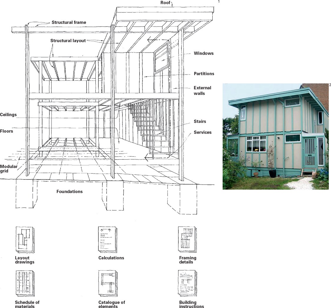
1 Segal Self-Build. Diagram showing the various elements and the sequence in which tasks are done.
2 Walter’s Way, London,1985–87.
Location: Sydney, Australia
Completion date: 1973
Size: 610 x 400 ft
Materials: Reinforced concrete
Architect: Jørn Utzon
Engineer: Ove Arup
Jørn Utzon’s winning entry in an international architectural competition in 1957 was said to have been excluded by the technical judging panel, but later reinstated on the recommendation of one of the judges, architect Eero Saarinen.
Work on the Sydney Opera House started in 1959. Geometrically, each half of each shell is a segment of a sphere; however, the “sails” were originally designed as parabolas, for which an engineering solution could not be found. Although described as reinforced-concrete shells, each one employs a series of hollow concrete ribs that support a total of 2,194 precast-concrete roof panels (or distinctive arrow-shaped tile lids) which are in turn clad with a total of over 1m tiles. The tiled surface is highly detailed and uses two types of tile – one white, one cream – with clearly expressed joints. It was the intention of the architect that the building operate simultaneously at both building and human scale.
The opera house is supported on 580 concrete piers sunk up to 82 ft below sea level.
The design of the shells involved one of the earliest uses of computer analysis in order to understand the complex forces that the shells would be subject to, and it took some years to find the solution – that all the shells would be created as sections from a sphere and be supported on arched ribs.This solution avoided the need for expensive formwork construction by allowing the use of precast units which could be tiled at ground level. Large parts of the site were used (throughout construction) as a factory for these precast components.
The design and construction process was high profile and not without controversy. The opera house was to be built on Bennelong Point adjacent to Jon Bradfield’s Sydney Harbour Bridge and would be visible from all sides.
In 1966 during an interview for Danish television, Utzon said “...it was an ideal project for an architect...first because there was a beautiful site with a good view, and second there was no detailed programme.” The job proved a highly complex one, even with the assistance of engineering firm Ove Arup and, more specifically Jack Zunz (see HSBC Headquarters, page 168) and young assistant Peter Rice (see Pavilion of the Future, page 170).
On 1 March 1966 Utzon announced that he was quitting the job, a forced resignation because he had not received fees owing to him and there had also been a more general breakdown in communications with the client.
On 20 October 1973 the Sydney Opera House (completed by Hall, Todd and Littlemore) was officially inaugurated by Elizabeth II. Utzon never returned to visit the opera house finished by others, but in 1999 he was re-engaged to work on the building’s interiors, assisted by his son and partner, Jan, who oversaw the work. The subsequent renovation of the reception hall led to its being renamed the Utzon Room.

1 Diagram shows the segments of a sphere that make up the “sails” of the Sydney Opera House.
2 Exterior photograph showing the tile detailing.

Location: Hong Kong, China
Completion date: 1985
Height/Weight: 600 ft/33,000 tons of steel
Architect: Foster + Partners
Engineer: Arup (Jack Zunz)
A modular building with many prefabricated elements, the Hong Kong and Shanghai Bank headquarters employs just four vertical ladder-type, Vierendeel trusses as columns from which a series of double-cantilever elements (suspension trusses) are used to suspend the floors in groups of seven. The two-story suspension truss frames divide the structure vertically into five visually separated components with the two-story trusses inhabited as reception, dining and conference areas. These are connected to open-air terraces, cleverly created by pulling back the climatic envelope away from the structural frame. The terraces are designated recreational spaces, but are also treated as refuge zones in case of fire. The cross- bracing at the suspension truss levels is pin- jointed at the masts, a technology more commonly associated with civil engineering structures such as bridges, but used to cope with the huge loads and avoid bulky and labour-intensive bolted connections.
The unique “exoskeletal” structure provides large internal spaces that are clear of supports and allow for maximum future flexibility of the office space, of which this building provides more than 1m sq ft.
The HSBC building has 47 storys and four basement levels, and is clad in 4,500 tons of aluminum.
Natural sunlight is reflected into the lower-level internal spaces through the use of two sun scoops; one internal, one external. The external sun scoop consists of a giant bank of movable mirrors mounted on a truss structure on the South side of Level 12 (to correspond to the top of the 170 ft high atrium). These heliostats are programmed to track the sun throughout the year and reflect sunlight onto the internal sun scoop (or fixed bank of convex aluminum mirrors) which directs light around the atrium towards the plaza below. In addition, sun shades are provided on the external façades to block direct sunlight entering the building and thus reduce heat gain.
All flooring is made from lightweight movable panels in order to gain access to the service infrastructure below, including air-conditioning, electrical and telecommunication points.
Norman Foster had at the time never built a building of more than four storys but successfully employed a unique structural system to create what ultimately became home to 4,000 bank workers.
The design and construction of the project produced over 120,000 drawings and was a truly international collaboration with cladding from the USA, structural steelwork from the UK and suppliers and fabricators and contractors from Hong Kong and Japan.
At the time of the HSBC headquarter’s completion in 1985 it was the most expensive high-rise building ever constructed, costing an estimated US$670 million. The project propelled Norman Foster into global recognition and allowed for the closest that architecture has to research: a significant budget with the means to indulge, prototype and test architectural technology to its contemporary limit.
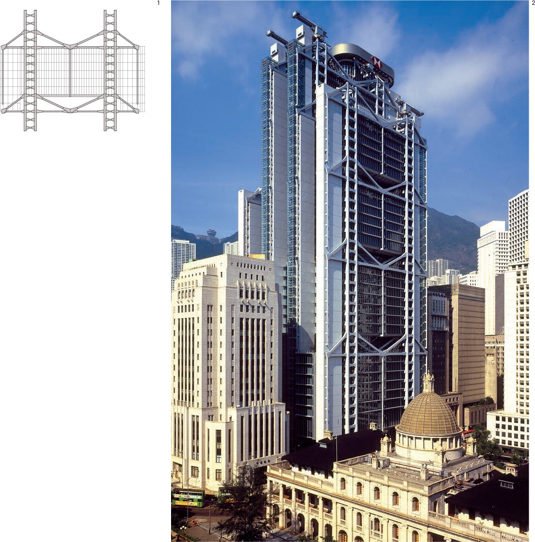
1 Diagram of a two-story suspension truss.
2 The Hong Kong and Shanghai Bank headquarters.

Location: Seville, Spain
Completion date: For Expo ’92
Height: 127 ft
Materials: Stone and steel
Architects: Martorell Bohigas Mackay (MBM)
Engineer: Peter Rice
Peter Rice was born in Ireland in 1935. He joined Arup in 1956 and much of his early career was spent working on the Sydney Opera House, contributing to geometric and model studies and carrying out analytical studies. Following his time in Australia he took a year’s sabbatical as visiting scholar at Cornell University, where he wanted “to study the application of pure mathematics to engineering problems. I think that a more thorough understanding of the nature of the equations used to solve structural problems in design could lead to a better conditioned solution and ultimately to a better choice of structural component.”
For the Pavilion of the Future, Rice designed a series of interlocking arches, visually resembling the stone aqueducts of old, that employed the compressive strength of stone and the tensile strength of steel. Unlike in reinforced concrete, however, the steel used to both reinforce and stabilize the structure was expressed externally. Similarly, the stone elements were reduced to the minimum cross-section needed for strength. The stone, Rosa Porina granite, was cut to extremely high tolerances (of less than 1⁄50 in) by computer-controlled cutting machinery. Each piece was 8 in square and 4 ft 6 in long, and the pieces were joined using epoxy resin to form prefabricated modular units of 16 ft 5 in by 1 ft 8 in by 1 ft 8 in.
Because the weight alone of these “skeletal” stone arches was not enough to provide stability, each arch was vertically braced using a unique system of stainless-steel rods and ties.
One difficulty encountered during construction was that the natural rift plane of the stone (the grain in timber) was not consistent or directionally uniform, so the stones’ specific directional strength was hard to calculate.

1 Diagram detailing the interlocking arches of stone and steel.
2 The stone and steel “braced” arches of the Pavilion of the Future. Photographed in 1992.

Location: Lisbon, Portugal
Completion date: For Expo ’98
Size: 165 x 220 ft
Weight: 1,500 tons
Materials: Reinforced concrete
Architect: Álvaro Siza Vieira
Engineer: Arup
Portugal’s most famous living architect, Álvaro Siza, constructed the exhibition building of the host country for Expo ‘98. The brief for the pavilion was that it was to be the venue for a temporary multimedia presentation for the duration of the Expo and provide a large external area for state visits and other ceremonial occasions. The architectural critic and theorist Kenneth Frampton, writing in Álvaro Siza – Complete Works, said this indeterminate brief had led to Siza designing the project as a palace and “Bringing him to adopt a monumental syntax.”
The curved reinforced-concrete roof is supported on two ceramic-clad porticoes. The stainless-steel tensile support cables are visible at each end of the span where they are attached to loadbearing walls. These walls sit in the same plane as the reinforcing bars and are designed to withstand the enormous lateral loads, like the masts and tie-backs of a suspension bridge. Engineered by an Arup team headed by the celebrated Cecil Balmond, the canopy’s structural support was separated from the other parts of the building due to Lisbon’s seismic activity.
The roof, 8 in of concrete, drops only 10 ft over its 65 m span. Devoid of lighting or drainage systems, this thin concrete skin spans the 213 x 164 ft plaza like a sail. Rainwater runs down the slightly sloping roof towards the harbour basin and falls freely to the ground.
This huge “concrete catenary” held between two free-standing façades bears striking similarities to German engineer Fritz Leonhardt’s swimming hall at Wuppertal (1954–56), which was a 213 ft wide concrete catenary held between the upper edges of two grandstands. Leonhardt, incidentally, worked with Gutbrod and Otto on the German Pavilion for the Montreal Expo (see page 160).

1 Diagram shows the ceramic-clad porticoes supporting the curved concrete roof.
2 The Portugal Pavilion pictured during Expo ‘98.
The Lord’s Media Centre

Location: London, UK
Completion date: 1999
Capacity: 250 people
Weight: 110 tons
Materials: Aluminum
Architects: Future Systems
Engineer: Arup
Contractor: Pendennis Shipyard
The Media Centre for Lord’s cricket ground in north London was designed to house 120 writers, 100 broadcasters and a 50-seat restaurant.
The main building is prefabricated in 26 sections approximately 10 by 65 ft, each weighing between 4.4 and 6.6 tons. The shell was preassembled off site in a boatbuilder’s yard and then reassembled at Lord’s. The building industry refused to tender for the building and only one boatbuilder took up the challenge.
Amanda Levete, a director of Future Systems, says that when the practice was invited to submit ideas for a new Lord’s Media Centre, “we decided to go for broke.” Critic Martin Pawley, writing in The Architects Journal in 1998, described the Media Centre as “a semi-mythical beast, half boat, half gazing eye, which has at last become believable.”
Monocoque structures (also known as stressed-skin structures) are lightweight and are commonly used in the aircraft, automobile and shipbuilding industries. The Media Centre is the first all-aluminum semi-monocoque building in the world, and is composed of an aluminum skin supported by a ribbed (coffered) framework of ¼ in and ½ in aluminum sheet metal. The prefabricated sections were welded together on site, with the welds subsequently ground down and spraypainted, creating a continuous smooth surface. The monocoque structure allows for unobstructed views onto the pitch.
The Media Centre is carried 49 ft above ground on two concrete towers that contain stairs and lifts, and from which the rigid aluminum structure cantilevers in every direction. The structure also contains an inclined non-reflective glass façade and air cooling to mitigate the effect of direct sun.
At the specific request of the British Broadcasting Corporation’s (BBC’s) venerable radio commentary team on Test Match Special, there is one opening window in the otherwise seamless glass façade. This window allows the commentators to hear the ball being hit without the aid of artificial amplification.
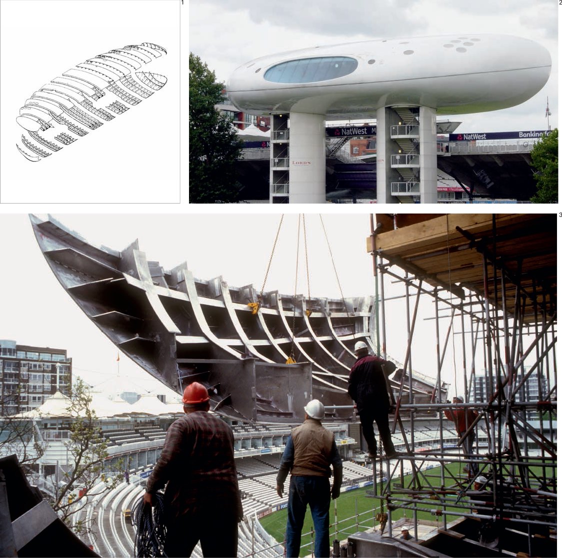
1 The prefabricated sections of the Media Centre, engineered in Europe and welded together on site.
2 Rear view of the Media Centre showing the two concrete support towers.
3 On site assembly of one of the prefabricated aluminum sections.

Location: London, UK
Completion date: 2004
Weight: 77,000 tons
Height: 590 ft
Materials: Glass and steel
Architects: Foster + Partners
Engineers: Arup
Contractor: Skanska UK
Steelwork fabrication: Hollandia BV, Viktor Buyck Steel Construction NV
Most tall buildings get their lateral stability from a rigid central core. However, with this tower the exoskeletal frame braces the structure through triangulation as well as carrying the floor loads – each floor rotates 5 degrees from the last. Despite its overall curved glass shape, there is only one piece of curved glass on the building – the lens- shaped cap at the very top – tapering into the crown, it reduces wind resistance.
Windows in the light wells open automatically to augment the air-conditioning system with natural ventilation. The atria are arranged in a spiral so that air drawn into the tower via the light wells circulates around the building due to the differences in external air pressure. The office areas consist of a double-glazed outer layer and a single-glazed inner screen, which sandwich a central ventilated cavity that contains solar- control blinds.
The building contains 333 piles in the foundations, 22 miles of structural steel at 12,000 tons, and 258,300 sq ft of glass cladding. The lifts can carry a maximum of 378 people at any one time reaching speeds of 19 ft per second, and almost all the plant space is located externally on an adjacent six- story structure at 20 Bury Street.
This 41-story office block provides 822,370 sq ft of accommodation, including offices, a new public plaza at ground level, and a club room atop the structure that provides a 360-degree panorama of the city. 30 St Mary Axe is claimed to be London’s first environmentally sustainable high-rise, utilizing up to 50 per cent less energy to drive its heating and cooling system.
The shape of the tower was specifically tailored to its immediate local environment and the constraints of a tight City of London site. Its geometric profile was designed to reduce reflections, thus making the tower appear more transparent. The shape of the tower is also designed to reduce the effects of “down-draft” or winds at ground level that occur with high-rise developments, while creating pressure differentials across the service area to drive the unique natural ventilation system.
In 2004, 30 St Mary Axe was awarded the Royal Institute of British Architects (RIBA) Stirling Prize for building of the year. In his acceptance speech Norman (Lord) Foster said that the structure “... is an embodiment of the core values that we have championed for more than thirty years: values about humanizing the workplace, conserving energy, democratizing the way people communicate within a building, and the way that the building relates to the urban realm.”
This project develops ideas explored at the HSBC headquarters in Hong Kong (1985), the Commerzbank in Frankfurt am Main (1997) and the theoretical Climatroffice, an early collaboration between Foster and Buckminster Fuller (1971), which explored a dynamic mix of nature, office and space frames as future workspaces.

1 Segment revealing the internal structure of the tower.
2 30 St Mary Axe, or the “Gherkin” as it is more popularly known.

Location: Doetinchem, the Netherlands
Completion date: 2003
Height: 40 ft
Materials: Glass-reinforced epoxy (GRE)
Architects: Nox Architecture
The “D” Tower is made from 19 separate, laminated panels, assembled on site, and made from glass-reinforced epoxy (GRE) that was cast in molds. The molds were assembled from expanded polystyrene blocks that had been cut to form the complex surfaces by computer numerically controlled (CNC) milling machines.
The structural geometry is very similar to that of a Gothic vault, where columns and surface share the same continuum, except that the parts are glued and bolted together.
The reason for the use of epoxy is that the building was designed to glow, using different-colored lamps that responded to the mood of the inhabitants of Doetinchem (who were able to send messages to the building via a web site). The reason for the complex geometry is that the tower was designed to simulate a large, beating human heart.

1 Assembly schematic for the 19 components.
2 Cutting the expanded polystyrene blocks.
3 Each mold is built using an assembly of blocks; the panel is formed by laminating the mold.
4 Test assembly.
5, 6 Night-time views indicating the “chromatic” mood swings.
7 “D” Tower.

Location: Royal Botanic Gardens, Kew, London, UK
Completion date: 2005 Height/width/span: 33 ft/49 ft/62 ft
Materials: Painted steel and structural glass
Architects: Wilkinson Eyre
Engineers: Structural – Dewhurst MacFarlane, Environmental – Atelier 10
Each twin arch is formed from an upper and lower arch, spanned by tension rods which are anchored to a concrete retaining wall at ground level. The arches were fabricated from mild steel flat plates cut to a curve and welded together to make rectangular sections measuring 9½ x 4¾ in. The stainless-steel tension rods also carry the faceted glass panels. Alpine plants have to be dry, cool and well ventilated, and need to receive lots of light. The height of the glasshouse encourages air to move upwards (through vents at top and bottom) and the concrete base acts as a heat sink – a small fan draws cool, night-time air through a maze of concrete passages beneath the floor, and a series of vents directs the cool air upwards during the day (see also Thermal Mass, page 80). The building is north-south oriented so as to present a narrow profile to the sun. Low-iron glass gives nearly 90 per cent transparency, while mechanical solar shading may be deployed across the façade like a fan.

1 “Exploded” axonometric drawing describing the structural logic and principal structural and cladding elements.
2 Thermal control. Cross-section drawing showing air movement and temperature.
3 View of the Davies Alpine House with the solar shading deployed.
Location: Stratosphere
Start date: 1998
Engineer(s): International
Weight: 471,444 lb*
Habitable Volume: 15,000 cu ft*
Dimensions: Span of Solar Arrays 240 ft*
Length: 146 ft from Destiny Laboratory to Zvezda; 171 ft with a Progress vehicle docked
Truss: 191 ft
Height: 90 ft
The future of construction technology can perhaps be illustrated by the orbital assembly of the international space station (ISS). Pre-fabricated construction elements are ferried into space and assembled using both manpower and sophisticated robotics. The construction elements themselves are the product of an advanced materials science that results in increased lightness of elements along with their ability to withstand extreme environmental conditions (though not gravity!). The space shuttle and two types of Russian launch vehicles have so far launched a total of 45 assembly missions.
*Statistics as of December 2006

1 ISS Assembly Mission 1: The Zarya control module was launched atop a Russian proton rocket from Baikonour Cosmodrome, Kazakhstan on 20 November 1998. Zarya provides battery power, fuel storage and rendezvous and docking capability for Soyuz and Progress vehicles.
2 ISS Assembly Mission 2A: Space shuttle Endeavour delivered the unity node with two pressurized mating adapters. On 6 December 1998, the STS-88 crew captured the Zarya control module and mated it with the unity node inside the shuttle’s payload bay. On Sunday 13 December, space shuttle Endeavour undocked from the young international space station for the return to Earth.
3 ISS Assembly Mission 2A: The STS-101 crew readied the international space station for the arrival of the Zvezda service module. Four new batteries, ten new smoke detectors and four new cooling fans were installed in the Zarya control module. Handrails were installed on the unity node for future space walks.
4 ISS Assembly Mission 4A: The STS-97 crew delivered and installed the P6 truss, which contains the first US solar arrays. The P6 was temporarily installed on top of the Z1 truss. The P6 provides solar power with solar arrays and batteries, called the photovoltaic modules.
5 ISS Assembly Mission LF 1 STS-114, the space shuttle’s return to flight mission, delivered supplies and equipment to the international space station. An external stowage platform was installed with the assistance of space shuttle Discovery’s robotic arm and two space walkers. Also, spacewalkers restored power to a failed control moment gyroscope and installed a new one.
6 ISS Assembly Mission 6A: Space shuttle Endeavour delivered racks inside the Raffaello multi-purpose logistics module to the Destiny laboratory. Canadarm2, the station’s robotic arm, walked off the shuttle to its new home on the international space station. An ultra-high frequency (UHF) antenna that provides space-to-space communications capability for US-based space walks was installed on the station.
7 ISS Assembly Mission 11A: Space shuttle Endeavour delivered the first port truss segment, P1 truss, that was attached to the central truss segment, S0 truss. Additional cooling radiators were delivered but remained stowed until ISS Assembly Mission 12A.1. A cart, known as the crew and equipment translation aid, was delivered to help space walkers move equipment along the integrated truss structure.
8 ISS Assembly Mission 1R: The Zvezda service module was launched atop a Russian proton rocket from Baikonur Cosmodrome on 12 July 2000. The Zvezda provides living quarters and performs some lifesupport system functions on the international space station.
9 The international space station is viewed from space shuttle Atlantis after undocking on Tuesday, 19 June 2007 at 10:42 am.
Picture captions courtesy of NASA, 2007.
Location: Barcelona, Spain
Dimensions: 145 ft x 145 ft x 125 ft high
Materials: Steel, glass, and ETFE
Architects: Cloud 9 (Enric Ruiz Geli)
Engineers: BOMA, PGI Grup Engineering
This exemplary new mediatheque building in Barcelona acts as a showcase for a whole series of technological and programmatic approaches to architecture. Described by the designers as having a hybrid program, the building is a mixture of commercial and public spaces for new technology start-up companies and more established media organizations. With a nod to the industrial heritage of the site, the architects took an early decision to invest a larger percentage of the total construction budget into the steel structure of the building (40% of the total construction cost as opposed to a more typical industry average of 25-30%). The building structure is formed by two steel-framed flank-walls, which then allows the two-floor “inhabitable” truss to be pre-assembled on the ground and winched into position using the structural walls as scaffolds. The steel gantry acts as a bridge support for the six floors, which are suspended from the truss on 6 in diameter tensile steel rods, as opposed to 20 in diameter columns had these supports been acting in compression. The logic of the suspended structure also creates a clear span ground floor between the southwest and northeast walls and to emphasize the nature of the structural intent, all internal tensile steel elements are painted with bioluminescent paint, which glows in the dark. Interestingly, the overall dimensions and proportions of Media-ICT take their inspiration from New York’s Ford Foundation building by Kevin Roche John Dinkerloo Associates (1967), where office accommodation is pushed up and outwards in its cuboid form to create a huge central garden/atrium.
The building structure is laterally stiffened by a network of diagonal steel bracing tubes that crisscross the façades, with the size and position of this eccentric diagonal grid determined by a Finite Element Analysis (FEA) of structural stiffness. The steel tubes are connected and fixed back to the structure by petal-shaped plasma-cut connector plates “flowers,” of which there are 120 different types.
One of the larger ambitions of this project is to create a more environmentally responsible and responsive building, which is particularly illustrated in the two Ethylene tetrafluoroethylene (ETFE) façades. The southeast-facing façade has an external skin of inflatable ETFE cushions, which act as a variable sunscreen, letting in more daylight and sunlight in the winter for solar heat gain, and becoming more opaque in the summer months to protect and shade the building’s inhabitants. The ETFE skin opacity is controlled through the differential movement of offset printed layers. The southwest façade uses a nitrogen and oilbased fog machine to control the opacity of huge vertical ETFE cushions, with the fog pumped into the top of building-height cushions, creating a huge translucent façade. This is the first time such a system has been installed in a building. Other key technical features of the building include a network of hundreds of local sensors (light, heat, and humidity) that work in conjunction with the façade, heat and lighting systems via an Arduino (microprocessor) network to regulate the internal building environment. Media-ICT’s roof is additionally covered with a garden encouraging biodiversity, photovoltaic cells and a rainwater collection system. The building achieves an A rated (the most efficient) Energy Performance Certificate.

1 Structural cross-section showing the central two-story truss and the centrally suspended floors.
2 Detail of southeast façade showing printed ETFE cushions.
3 Photograph of the southeast façade showing the bracing bars, “flower” connectors and ETFE cushions.
Location: Amsterdam, The Netherlands
Dimensions: Height 59 ft, length 328 ft, width 131 ft
Materials: Steel frame and Fiber
Reinforced Polymer composite panels
Architects: Benthem Crouwel Architects
Engineers: Arup
The building skin of this extraordinary museum addition is one of a small (but increasing) number of buildings that utilize the technology of fiber reinforced polymers (FRP) in construction. Widely used in the fabrication of yachts, aeronautical engineering and high performance sports products such as tennis rackets, this is the first time that this composite has been used for a large-scale building façade.
The new museum extension houses the largest free-span exhibition space in Amsterdam, a black box performance and audio visual room, offices, museum shop, restaurant, and library. In addition the distinctive cantilevered peak re-orientates and marks the entrance to the museum on to the Museumplein (museum square) connecting the Rijksmuseum, Van Gogh Museum, and the Concertgebouw.
The architect Mels Crouwel explains that the white coloring of the museum addition was inspired by the former Stedelijk Museum Director Willem Sandberg, who, during his tenure in 1945 -1962, paired down the interior of the original 19th century building, developed a distinctive typographic identity and painted the interior white. The new addition uses a steel framed structure clad with composite panels. These 271 prefabricated elements (some as large as 49 ft x 10 ft) are attached to the precision steel internal framework with 1,100 specially designed aluminum anchor connections. After installation the separate panels are bonded together on site to create a seamless monolithic structure. The composite “sandwich” panels consist of carbon and aramid (Twaron®) fiber laminates and special resins in order to produce a façade with a low thermal expansion coefficient, crucial for the 328 foot long construction. The composite panels were manufactured by Holland Composites and cover an area of approximately 9,840 square feet and weigh less than half of a typical curtain wall.

1 View showing the new museum extension with its 41 ft long cantilevered roof and entrance. The Museumplein is to the right of the image.
2 Cross-section drawing through the original 19th century museum and the new vessel-like addition.
